In this post we study about a automatic fan speed regulator circuit for controlling the temperature of a heatsink and from preventing the temperature to reach dangerous levels. This approach is to ensure safeguarding of the connected devices wit the heatsink.
Written by: Preeti Das
With the help of this circuit the speed of a fan motor self adjusts depending on the temperature of a heatsink that is intended to be controlled.
How it Works
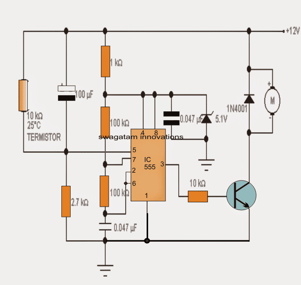
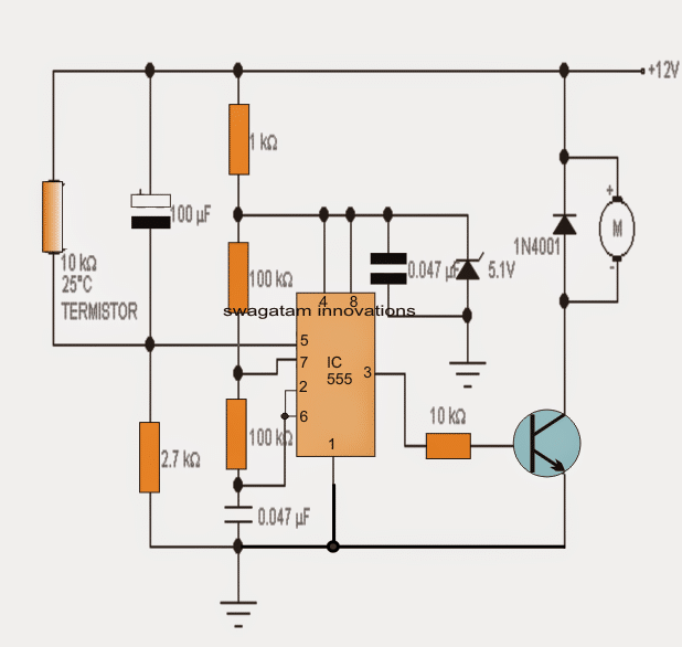
Here a standard thermistor device is used as the temperature sensor specified with a resistance value of 10 K at 25 degrees ambient temperature.
The motor to be controlled is powered by the PWM pulses from the IC 555 whose pulse rate cycle goes down from around 34% at room temperature (minimum speed) to 100% (maximum speed) when the temperature has reached a high.
These pulses are generated by 555 which is rigged to work as an integrated voltage controlled oscillator circuit. On the control voltage pin 5 a varying voltage is applied determined by the resistance of the thermistor which in turn depends on the temperature generated over the heat sink.
In order to ensure an immediate transfer of temperature, the thermistor must be attached or glued to the heatsink appropriately.
The shown 100uF capacitor connected in parallel with the thermistor shorts the supply with pin5 of the IC simulating a high temperature state for a few seconds during power switch ON so that the motor gets an initialization torque and is prevented from getting stalled.
The voltage to the IC 555 is regulated by the zener diode of 9,1V so that it allows the IC to work regardless of the input supply fluctuations.
To adjust the temperature triggering threshold at which the motor may be expected to speed up, you can change the value 2.7K resistor connected to pin 5 of 555 or even use a potentiometer for setting up the same.
Circuit Diagram

Note: The Transistor can be TIP122 for small motors rated at around 1 amp current.
2) Using LM358
Most electronic circuits with heat-generating power semiconductors equip at least one heatsink to dissipate the large amount of energy consumed. The rating of a heatsink depends on the maximum permissible temperature the silicon chip can withstand.
In this automatic heatsink temperature controller project, the heatsink monitor continuously observes the temperature of the heatsink.
In the range of 50°C to 60°, C the green LED will be lit, and the yellow one will light up when the temperature in the 70° - 80°C range.
Finally, when the temperature crosses the 80°C mark, the red LED will turn on. There is also an option to disconnect the load using a relay.


Naturally, the circuit is a window comparator. Sensor D1 delivered a control voltage escalates at a rate of 10 mV/°C.
When the sensor voltage drops below the voltage of wipers P1 and P2, the outputs of the opamps (A1 and A2) will become low and LED D2 will illuminate.
Output A1 will become high when the voltage across D1 goes above the wiper at P1 but still stays below of P2.
At the same time, D2 will be off and LED D3 will be lit. If the voltage crosses the wiper of P2, then both opamps’ output will be high.
Simultaneously, D5 will light up and the transistor T1 will be switched on. The function of Zener diode D4 is to make sure LED D5 is brightly lit as well as ensuring T1 conducts without inhibition.
How to Calibrate
Calibrating the unit is quite straightforward. You just need to place the sensor along with a calibrated thermometer in a plate of water. The next step is to heat it.
As the temperature rises, set P1 and P2 to a minimum and maximum resistances.
Also, set the cross over from green to yellow in the range of 50° - 60°C with P1. After that, set the limit from yellow to red in the range of 70° - 80°C with P2. Now that you have calibrated the sensor, you can attach it directly onto the heatsink.
