In this post I have explained how to make a simple railway signal lamp which can be used by the guards for providing a handheld signalling to the various trains with the many specified signalling modes. The idea was requested by Mr. Bala.
Technical Specifications
I need a project design for railway led signalling light . The light must have 4 modes. 1) red stable 2) green stable 3) red flashes 4) green flashes also suggest suitable charges for the circuit.
The Design
The proposed railway signal lamp circuit using flashing LEDs can be implemented through a simple IC 555 astable circuit as shown below:
Circuit Diagram

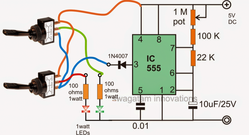
Referring to the above diagram, the circuit may be understood as I have explained below:
Circuit Operation
The IC 555 is configured in its standard astable mode which is supposed to generate alternate ON/OFF potential at its pin#3.
The IC is capable and is rated to deliver up to around 200mA current, therefore 1 watt LEDs become suitable for working directly with this pinout of the IC.
Since the 1 watt LEDs are rated to handle 350mA, the available lower amount of current allows the LEDs to work without heatsinks, yet so, with 100mA current the light from these LEDs can be expected to be significantly bright and quite applicable for the requested railway safety signal lamp application.
The 1M pot is used to adjust the flashing rate on the LEDs, while the switches determine the LED operational modes as per the requested specs.
The switches must be SPDT type with CENTER OFF facility.
Toggling the relevant switches downwards produces a constant switched ON response on the LEDs, while toggling them on the lower side allows the LEDs to flash.
The center OFF feature of the switch can be used for keeping the LEDs shut off.
The LEDs must be housed inside high gloss reflector cones for getting an enhanced light output and an increased visibility range.
Dear sir I want to make flashing light of railway so give me a real circuit diagram of flashing signal torch
Dear M Verma, please tell me the power of the LEDs you want to use.
Hello,
I’d like to re-purpose this circuit for use in a model, and was wondering if there’s enough voltage to drive 2x green LED and 2x red LED.
Regards,
Mike
Hi, for 2 LEDs you will need a minimum of 6V supply. Alternatively you can use any supply up to 15 V and dimension the LED resistors using the following formula:
R = Supply – (3.3 + 3.3) / LED current
Much appreciated – I’ll have a go at this!
My pleasure!
Sir please give the 5 volt usb charger circuit diagram for this ckt. To make it rechargeable circuit
Sandip, you can try this:
https://www.homemade-circuits.com/usb-automatic-li-ion-battery-charger/
thank you sir , i will try and tell you back .if you have time kindly draw the circuit.
bala
Please try it, if you find it too difficult, then I may possibly update the drawing in the above article….
sure sir .
dear sir , i did the circuit. it is working wonderful. i have a small request to you that the LED brightness is not enough for my application. kindly do the need full.
Thank you
Bala
dear bala,
take a TIP127 transistor connect its base through a 1K resistor with pin3 of the IC directly, remove the 1N4007 diode, and the blue wire.
connect its emitter to the positive line.
connect the blue which was removed earlier with collector of the transistor.
now change the resistor f the LEDs to 20 ohm or 10 ohm 2 watt each…making sure the LEDs are mounted on large heatsinks
thank you so much sir, i will do this circuit . after that i will give you feedback .
bala
you are welcome bala…
brilliant circuit. thank you so much . i will do it in practical and give you feed back .
bala
Sir,
LED is constantly glowing on one side of switch but not blinking on the other side of the switch. Please suggest.
Thankyou
Giri, Connect a 3rd LED from the 1N4007 cathode to ground through 1k resistor. check whether this LED is flashing or not. If not then your IC 555 circuit is faulty. If yes, then your switch wiring may be incorrect. Please check these issues.