In this article we investigate the flywheel concept and learn how it may be used for charging batteries and also enhance to work at the overunity level.
What is a Flywheel
According to Wikipedia, A flywheel is a spinning mechanized machine utilized to stock and release rotational power.
Flywheels are seen to possess an inertia, termed the "moment of inertia" which therefore resists alterations in rotational to their speeds, much like the mass (inertia) of an automotive system prevents its acceleration.
The level of power trapped in a flywheel is proportional to the square of its rotational movement.
Energy is delivered to a flywheel by the utilization of a torsional power to it, consequently raising its rotational velocity, and as a result its accumulated power. On the other hand, a flywheel produces collected energy by making use of torsional power to a physical load, consequently lowering the flywheel's rotational rate.
Typical applications of a flywheel incorporate:
Offering nonstop energy where the source of energy is discontinuous. As an illustration, flywheels are utilized in reciprocating motors since the power source, torque from these motors, are irregular.
Dispensing energy at rates beyond the capability of a persisting source of energy.
This is often accomplished by gathering energy in the flywheel progressively then simply discharging the energy swiftly, at rates that surpass the capabilities of the source of energy.
Managing the alignment of a mechanised equipment. In this kind of usages, the angular speed of a flywheel is specifically routed as a torsional power to the connecting mechanized system while energy is moved to or from the flywheel, consequently provoking the connecting equipment to move into certain expected position.
Flywheels are ideally made from steel and move over special high grade bearings; these are typically confined to a revolution value of several thousand RPM.
A number of contemporary flywheels are constructed of carbon fiber components and implement magnetic bearings, making it possible for these to rotate at rates up to 60,000 RPM.
The above discussion clearly states that flywheels have the potentials to generate an output power that may much higher than the input once it has been rotated to some specified high speed.
From the above discussion we can conclude that using a flywheel an overunity electricity generator can be achieved without much complications and skepticism.
Considering Flywheel as an Effective Free Electricity Generator
In a one of my earlier posts I have discussed a similar concept using a pendulum and have tried to convey the method of using it for achieving overunity limits.
In this article we'll see how a flywheel can be used for executing an overunity result, and derive over 300% more output than the applied input.
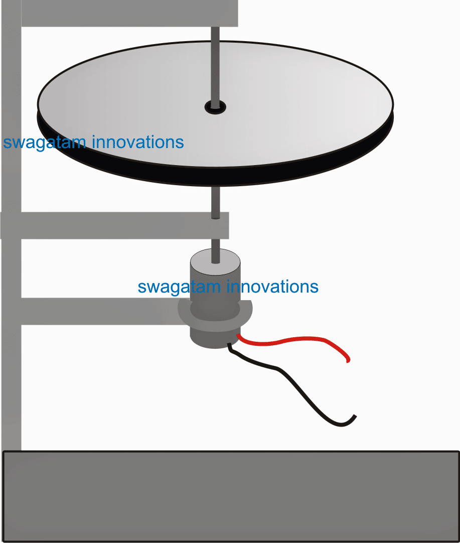
In the diagram below we can see a simple flywheel with a motor set up:

This can be seen as a manual electricity generator using a flywheel wherein the flywheel needs to be pushed occasionally for sustaining a consistent rotation over the attached motor.
The motor wires can be appropriately terminated with a battery for acquiring the proposed free electricity from the set up.
The advantage of this set up is that once the flywheel is rotated with the specified maximum torque, the rotational can be sustained by pushing the flywheel with significantly less amount of energy.
Although efficient, the above set up may not look too impressive due to the requirement of an individual all the time near the system.
Using Flywheel for Generating Free Electricity
In the above sections I have explained regarding how a flywheel can be used for generating excess electricity from its stored potential energy when it's given a swift spin using an external torsional force. In the following discussions we'll learn how the system can be made into a perpetual motion without the need of any external intervention.
In our last discussion we understood the naturally attributed overunity feature of a flywheel, and learned how it can be used like an efficient machine for generating free electricity with the help of a frequently applied external minimal sustaining force to it.
However, in order to transform the flywheel into a free electricity generator andalmost perpetual, and automatic without the requirement of any manual intervention, the following shown smart idea can be incorporated.
The Flywheel Circuit Setup

If the explanation provided in Wikipedia is believed to be correct, then the above design should work as per the proposed overunity concept here.
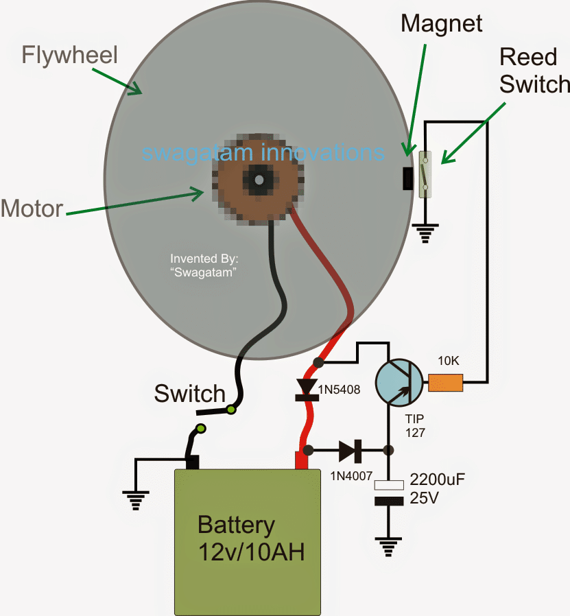
In the design above we can see an appropriately calculated flywheel, motor, and a battery circuit set up.
How it Works (Overunity)
The figure shows the top view of the flywheel, the attached motor being right under the flywheel, shown in a pixelated form.
The motor wires are connected to a battery which needs to be charged, via a blocking rectifier diode (1N5408). This diode makes sure that the voltage from the battery remains blocked while the energy from the motor is allowed to reach the battery.
A PNP transistor network can also be witnessed, whose base is configured with a reed switch.
The reed switch is supposed to be activated through an embedded magnet sealed at the edge of the flywheel.
Initially the switch connected in series with the negative wire is kept toggled off, and the flywheel is given is tight rotational spin (torque) manually or with any desired external means.
A soon as this is executed, the switch is immediately toggled ON.
Here the flywheel dimension is assumed to be significantly large such that the "switch ON" action (battery connected) inflicts only a minor resistance to the torque of the flywheel.
Once the above action is initiated, the motor instantly begins generating and supplying electricity to the battery.
Also in the course of its rotational cycle, the magnet attached with the flywheel edge begins switching the corresponding reed switch intermittently.
The reed switch in turn switches the PNP transistor at the same rate creating momentary short across the 1N5408 diode so that during these instants the battery power is reverted to the motor for applying back the required sustaining torque to it.
The 2200 uF capacitor further aids to this and reduces the load on the battery each time the transistor switches ON.
Now since the reed switch is toggled only for a fraction of time of each complete rotation from the flywheel, except for these periods, the rest of the rotational length of period is used for generating free extra electricity for the battery.
It implies that while the flywheel is rotating only a fractional energy from the battery is used for sustaining its optimal torque, while a significantly large amount of its energy is transferred to the motor for generating an equivalent amount of charging current for the battery.
The above explained scenario ensures a perfect self-sustaining flywheel system which becomes capable of generating free electricity in excess tow hat is being used as its sustaining input.
The shown 2200 uF capacitor may be increased to some higher value and if possible super capacitors can be tried for further enhancing the efficiency of the system.
Feedback from Mr. Mark Baiamonte
Can you use a 3 phase washing machine motor and how would it be wired? I have been fooling atound with a windmill and got it to work but not enough wind. You plans are excellent and i would love to try it. Here is my motor.
Solving the Query
A 3 phase motor could be difficult and confusing to wire with the shown flywheel circuit, because the motor would need a 3 phase to single phase DC conversion and a DC to 3 phase reception from the transistor...
Finalized Flywheel Design By Mark
I built the flywheel and it works! I only had a 2200uf 16volt. I used a motor from a treadmill.
What the biggest size capacitor i could use? Thank you very much. This is the first thing i made like this. I enjoyed it very much.
Only sorry i didn't start fooling around with this kind of stuff at a younger age. Thank you again for your design and your time.
Mark Baiamonte Ashley,
Pa USA
primoswilkesbarre@gmail.com
My Response
That's great Mark, thanks for updating the info.
The capacitor value is not critical, however bigger values might help to increase the efficiency of the system, so you could try adding a a couple of more 2200uF in parallel.
Best Regards
Swag
A Few Optimization Tips from Mr. Thamal Indika
I saw a big difference by attaching a 4700uf capacitor to the motor terminals and the speed of the fly wheel increased significantly. At the same time i checked the out put of the motor and it is about 6.5 V . I am going to rotate another motor by that output current and using that separate motor i can create a good generator by moving magnets on a fixed coil.
I hope to use super magnets like N38 (Diameter 2CM, Width 1CM) and use guage 20 coils . I can make an assembly for that and i will attach another fly wheel to the shaft attached to that separate motor so that the speed will be increased. . Then it will generate more that 12 V current and about 2 A. Also i can change the amount of ampere by attaching more coils . Then i can give that out put current to the 7.4 V 1A Dialog Router battery and it will charge well.
I think this is a good modification to your circuit design and instead of giving the output current of the battery through a rectifier , i am going to rotate another separate motor by that current and thus running a generator and supply the output of the generator to the battery. please note at present i use a 7.4V 2A Dialog Router with a 6V cassette motor for your design and the speed of the fly wheel increased significantly by attaching a 4700uf capacitor to the terminals of the 6V cassette motor .
It brought some successful results. I just checked the charger of this battery and it is 12V 1A charger . I hope i will be able to create a generator that would provide 12V 1A.