In this article I have explained a generator/UPS/Battery relay changeover circuit for implementing a customized optimization for a generator, UPS, battery power network, in order to enhance the operational efficiency of the system. The idea was requested by Mr. Sidingilizwe.
Circuit Objectives and Requirements
- First of all thank you for adding me to your circles. Do you offer any lessons on electronics and programming for a fee?
- I am also looking for a circuit where a 10kva diesel generator supplies power to a UPS which in turn charges a battery bank.
- After about 8 hours the ups must stop the generator so that the battery bank supplies the power. When the power from the battery bank is drained, the generator will restart again.
- Every week I have to refuel a 10kva single phase diesel generator which is located in a remote area without electricity. The generator has a DeepSea 7220 controller.
- The generator mainly gives power to an OUTBACK UPS/battery charger combo which then charges a battery bank. The UPS uses 24v from the battery bank to power a load.
- I want to minimize the time I spend refueling. So I want a circuit which runs the generator for say 8 hours to charge the battery bank. After that, the generator should stop running so that the UPS can use the power from the battery bank to supply a load.
- The UPS should stop giving power to the load when the voltage of the battery bank drops to say 21v.
- And when it stops, the generator should start running to give power to recharge the battery bank again.
- The present scenario is that I always leave the generator running until it runs out of fuel.
- I want a circuit which will give time to charge the battery bank and then the generator must stop. Such a circuit will reduce the time I spend traveling to refuel the generator and the generator will last longer.
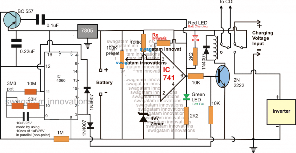
Circuit Diagram

Note: The IC741 should be rated at above 24V...or replace it with LM321 IC
Designing Generator/UPS Changeover
As per the request, the objective of the design is to switch off the generator after 8 hours, and switch it ON when the battery reaches its lower discharge threshold.
To implement this generator/UPS/Battery relay changeover, I have introduced two options in the design, one is using the IC 4060 timer circuit and the second using the IC 741 opamp comparator circuit.
The timer and the opamp both are configured to switch OFF the generator depending on which one toggles first. If the 8 hour period lapses first, then its the timer which switches OFF the generator and if the battery gets fully charged before this period, the opamp takes the initiative and switches OFF the generator, and switches ON the inverter.
The opamp comparator is configured in the usual way using the IC 741, its pin#3 is rigged as the battery voltage sensing input while its pin#2 is used as the reference limit, as fixed by the zener diode voltage.
As long as the battery voltage level is below the desired full charge level, the pin#3 potential is lower than the pin#2 reference, resulting in an output pin#6 with a logic low, this in turn keeps the transistor and the relay switched OFF (N/C contacts at the upper side).
In the above situation the first set of contacts of the relay which is supposed to be associated with the generator CDI, keeps the CDI switched ON allowing the generator to be operational, while the second set of contacts receives the charging voltage from the generator to charge the connected battery.
The battery at this position keeps on charging until it has reached the predetermined full charge level, which causes a slightly more voltage to appear at pin#3 compared to the reference level at pin#2 of the opamp IC.
As soon as the above situation is detected, the opamp quickly changes its output stance and switches it to a logic high, turning ON the BC547 along with the relay.
The relay's sets of contacts now flick towards the lower N/O side.
The hysteresis resistor Rx comes into action and makes sure that the opamp stays latched ON in this position until the battery has discharged to some lower unsafe level.
The above action causes the first set of relay contacts to switch OFF the CDI so that the generator is switched OFF, and the second set of the relay contacts enables the battery to get connected with the inverter, allowing the inverter mode operation for powering the load.
On the other side, if suppose the timer circuit which is made around the versatile 4060 IC becomes the first to switch ON (8 hours lapsed) before the opamp, its pin#3 goes high, and it sends a switch ON signal for the transistor relay driver stage.
This implies that in this position the battery may not be fully charged but may be close to the full charge level. However since the inverter needs to be switched ON anyhow even with whatever charge may be available from the battery, the relay is toggled ON by the 4060 output for executing the inverter mode operations.
The battery now begins discharging through the inverter, and after a course of time when it reaches its lower discharge threshold, the opamp hysteresis resistor succumbs to this lower level and releases the opamp latch.
This instantly reverts the opamp output situation and produces a low logic at its pin#6.
This low logic from the opamp does a few things in order to restore the situation the earlier condition:
First it switches OFF the relay switching ON the generator back and initiates the charging of the battery, additionally the low logic also sends a short triggering pulse to a PNP BC557 transistor which resets the 4060 timing and ensures that it makes a fresh start and begins counting from zero.....until 8 hours have elapsed yet again to keep the cycle moving.
The above explained generator/UPS/Battery relay changeover circuit for optimizing the generator, UPS, battery network power efficiency ensures a cyclic turn by turn operation of the stages and makes use of the resources in the most effective and optimal technique producing lower maintenance for the units, and increasing cost saving for the end user.
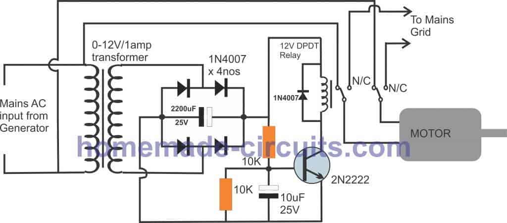
Generator Motor Auto Transfer Circuit
The following diagram shows an automatic transfer system designed to changeover mains supply from grid to the generator motor, as soon as generator starts generating power. More info can be found in the comment discussion below with Mr. SAA Bokhari
