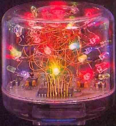
The glittering LED flower circuit we are presenting here holds significant importance in our artistic city and offers no particular interest other than delighting your view with various multicolored and varied light effects. This luminous LED flower is also unique in its design, allowing ample room for everyone's creative sense.
The goal is to control 32 different LEDs in an almost random manner. In fact, these LEDs will be divided into two independent groups of 16 LEDs, and two of them will be lit simultaneously. To simplify, we will only describe the functioning of one half of the electronic assembly, with the other half being identical.
The core of the setup relies on the use of a 16-channel analog multiplexer/demultiplexer. This type of circuit can be likened to a rotary switch with 16 positions.
Similar to its mechanical counterpart, the multiplexer/demultiplexer can only establish a single connection at a time between the common pin and one of the 16 channels.
The ranking of the connection depends solely on the binary code present at its four inputs: A, B, C, and D.
Typically, this code is generated by a binary counter, and the sequence of connections always occurs in the same order, which can become monotonous over time.
In our application, each input of the multiplexer/demultiplexer is independently controlled by a low-frequency oscillator with a different time constant.
The result is a quasi-random combination of connection orders, especially since temperature variations tend to increase the desynchronization of the oscillators.
Circuit Description
As we mentioned in the previous paragraph, the description will be limited to half of the diagram for controlling 16 LEDs.
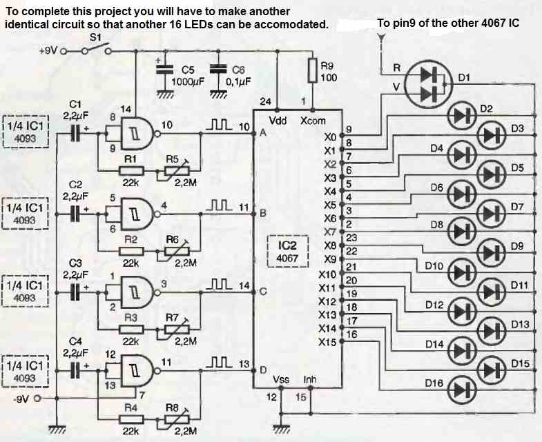
The four gates of the Schmitt trigger circuit, each associated with an adjustable component, a resistor, and a capacitor, form four variable low-frequency oscillators.
These are respectively R1, R5, C1 for pins 8, 9, 10 of IC1; R2, R6, C2 for pins 4, 5, 6 of IC1; R3, R7, C3 for pins 1, 2, 3 of IC1; and finally R4, R8, C4 for pins 11, 12, 13 of IC1.
The outputs 10, 11, 4, and 3 of the four oscillators respectively control the four binary inputs A, B, C, and D of the multiplexer IC2.
The common point, representing by analogy the cursor of a rotary switch, is connected to the positive terminal of the power supply through a limiting resistor R9.
The 16 outputs are connected to the anodes of the LEDs, and the cathodes are connected to ground through a common wire.
Each analog switch allows a nominal current of 25 mA to pass, but in reality, it can handle a higher maximum current.
The power supply is provided by a 9V battery, and the capacitors C5 and C6 provide strong decoupling at the closest point of the circuit.
The other half of the diagram is identical, and in the nomenclature, the components are designated in the same way with a prime symbol.
Construction
As you have already noticed from the photographs of this LED flower project, the entire aesthetic interest lies in the adopted circular shape.
Unfortunately, a circular shape implies a more challenging printed circuit board (PCB) to create, unless you use the following method:
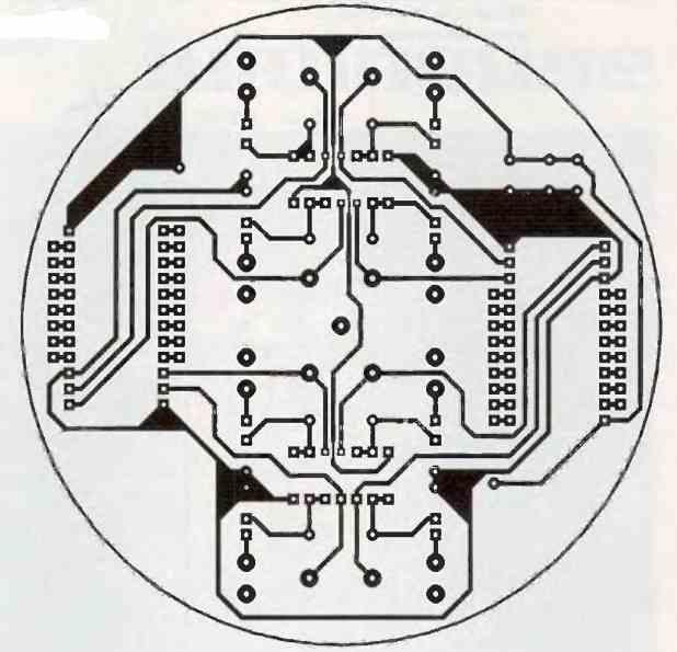
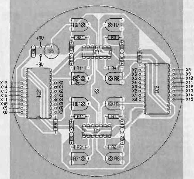
Start by creating the PCB on a square epoxy board using any method you are familiar with.
After drilling all the component holes, proceed to drill the central hole with a diameter of 5 or 6 mm, marked by a dot.
Then, rough out the circular shape by progressively cutting smaller angles and finish it with a file.
Once this phase is completed, insert a long metal screw with a diameter of 5 or 6 mm, along with a nut and a washer, into the central hole.
Secure it in the chuck of a drill set to a low speed.
Holding the drill firmly, use a fixed reference point and run the flat side of a file along the periphery of the PCB.
This will result in a perfect circular shape that can be further adjusted by applying gentle force with the file in the drill.
Once the PCB is complete, arrange the 10 resistors, 6 capacitors, 8 adjustable components, and don't forget the integrated circuit sockets.
Once the electronics are finished, the purely creative part of the project remains.
The model uses a cotton ball, commonly found in bathroom supplies, which can be obtained from a variety store. However, you have the freedom to choose a different model.
You may need to adjust the dimensions of the PCB accordingly.
In the lower part of the casing, drill a vertical hole with a diameter of 4 mm and glue a Meccano axle in place using component glue.
At the other end of the axle, attach a large pulley with a tire. This lower part will house the 9V battery with its clip connector and the general switch.
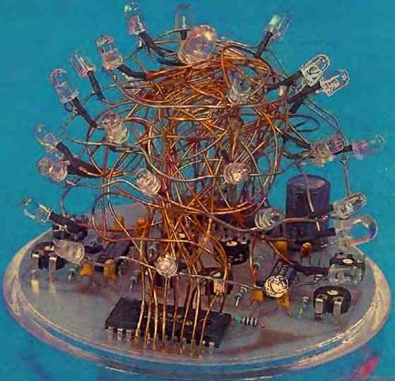
As for the LEDs, they will be connected to the IC using 32 pieces of enameled wire with a diameter of 6/10th of a length of approximately 15 cm, soldered to each of the 16 outputs of IC2 and IC2.
The common connection for the LEDs does not need to be isolated, so a sufficiently long tinned copper wire will suffice.
After this, the arrangement of the LEDs and wires is a matter of personal preference, and their practical order does not matter.
LED Specifications
You can take inspiration from the photos or arrange them as you wish.
However, pay special attention to the choice of LEDs.
It is preferable to use D5 mm models with very high brightness, having a luminous intensity of at least 300 mcd for a current of 20 mA, in colors such as red, green, or yellow, with a sufficiently wide emission angle.
There are also magnificent high-brightness LEDs in pure blue or green colors (wavelength of 525 nm), but they can be quite expensive (available at RADIOSPARES).
Your choice will depend on the budget you are willing to allocate for this project.
Once all the LEDs are soldered, ensuring their correct polarities (the enamel may melt locally due to the heat of the soldering iron), verify the proper functioning of the circuit, which should be immediate.
Finally, proceed with the empirical adjustment of the eight adjustable components to achieve a pleasing rapid blinking effect to the eye.
There is no doubt that this multicolored LED flower project will delight your vision and find a special place in your stylish interior.
The following image shows the connection details of the LEDs using rigid wires.
Need Help? Please Leave a Comment! We value your input—Kindly keep it relevant to the above topic!