In this post I have explained a simple configuration which can be used as a automatic changeover circuit for switching AC grid mains to generator mains, during power failures or outages.
The explained circuit will effectively switch the connected appliances to the generator mains during power failure however it won't be able to switch start the generator automatically, this will need to be done manually, because most generators involve a difficult mechanical actuation procedure.
How it Works
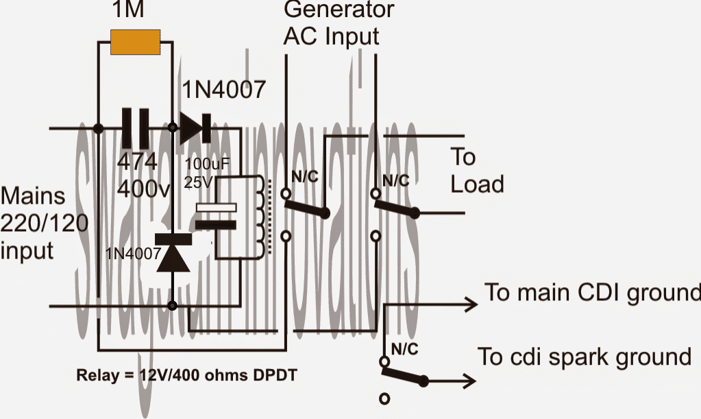
Referring to the given diagram we can see a simple circuit comprising of a TP relay (triple pole relay) as shown below, and a transformerless power supply circuit.
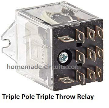
The input of the transformerless power supply circuit is connected to the mains 220V or 120V input.
When mains power is present, the connected relay activates with this power and switches ON the load or the appliances via its N/O contacts.
Conversely when mains power fails, the relay deactivates and connects with the N/C contacts which may be wired up with the generator mains.
Now as soon as the generator is pulled started, the mains finds its way through the connected N/O contacts of the relay to the appliances.
The third set of contacts is used for enabling and disabling of the CDI unit of the generator so that when mains is restored, the generator is automatically halted.
Simple yet effective.....
Circuit Diagram
Analyzing the Part Value Calculations
Voltage Divider Across the Relay (Using 474 Capacitor)
The 474 capacitor (0.47 µF, 400 V) acts as a current limiting element for the relay coil when connected to the AC mains (220 V or 120 V). The current through the capacitor can be calculated using the reactance of the capacitor:
Formula for Capacitive Reactance:
Xc = 1 / (2 * π * f * C)
Where:
- Xc = Capacitive reactance in ohms
- f = Frequency of AC mains (typically 50 Hz or 60 Hz)
- C = Capacitance in farads (0.47 µF = 0.47 * 10⁻⁶ F)
For 50 Hz mains: Xc = 1 / (2 * π * 50 * 0.47 * 10⁻⁶)
Xc ≈ 6,778 ohms
Current Through the Relay:
The current is determined by Ohm’s Law:
I = V / Xc
For 220 V AC mains:
I = 220 / 6,778 ≈ 0.0324 A ≈ 32.4 mA
For 120 V AC mains:
I = 120 / 6,778 ≈ 0.0177 A ≈ 17.7 mA
This current must be sufficient to activate the relay. Check the relays required current (based on its 12 V 400-ohm coil):
Relay Voltage and Power
The relay coil operates on 12 V DC. The current through the coil is:
Irelay = V / R
Where:
- V = Voltage across the relay coil (12 V)
- R = Relay coil resistance (400 ohms)
- Irelay = 12 / 400 = 0.03 A = 30 mA
This means that the capacitor-limited current (calculated above) has to be greater than or equal to the relay's required operating current of 30 mA for 220 V mains.
Diode Rectification
The diodes (1N4007) rectify the AC voltage into pulsating DC for the relay coil. The peak DC voltage after rectification is:
Formula for Peak Voltage:
Vpeak = Vrms × √2
For 220 V AC mains:
Vpeak = 220 * √2 ≈ 311 V
For 120 V AC mains:
Vpeak = 120 * √2 ≈ 170 V
However the relay sees only the voltage dropped across the capacitor and rectified output which limits the current to safe levels.
Filtering Using 100 µF Capacitor
The 100 µF capacitor smooths the rectified pulsating DC into a steady voltage for the relay.
The ripple voltage can be estimated using:
Ripple Voltage Formula:
Vripple = I / (f * C)
Where:
- I = Current through the capacitor (relay current, ≈ 30 mA)
- f = Frequency of rectified signal (100 Hz for full-wave rectification in 50 Hz mains)
- C = Capacitance in farads (100 µF = 100 * 10⁻⁶ F)
Vripple = 0.03 / (100 * 100 * 10⁻⁶)
Vripple ≈ 3 V
3 Phase Grid to Generator Changeover Circuit
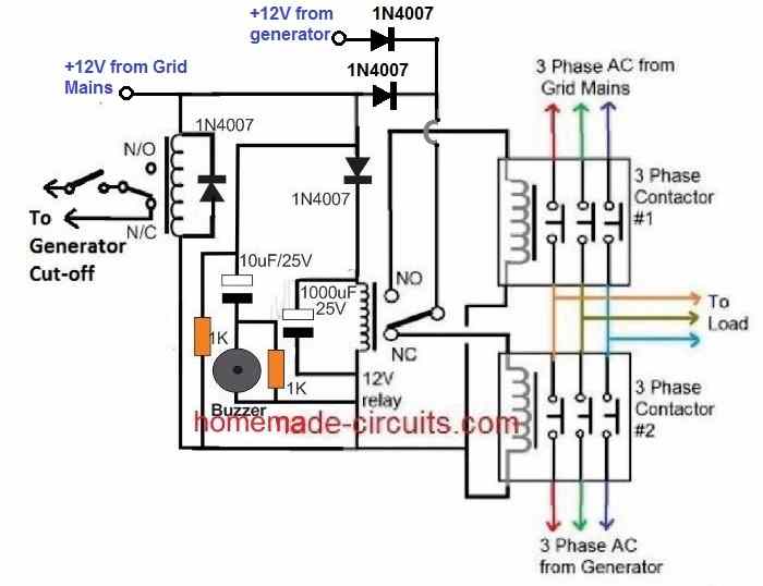
The following diagram shows how a 3 phase grid to generator changeover can be implemented using a couple of 3 phase contactors.
How the Circuit Works
Let's assume mains AC is not available, and generator is switched ON by the left side relay.
In this situation the center relay will be deactivated, and its pole will be connected with its N/C contact, so that the +12V DC from the generator passes through the N/C contact and actuates the bottom/right 3 phase generator contactor.
The top/right grid mains contactor remains switched OFF due to the absence of a +12V DC.
Therefore, the generator AC flows through this bottom/right contactor and operates the connected appliances or load.
Now, suppose the mains grid AC restores.
The left side relay activates and turns OFF the generator. Also, simultaneously the center relay switches ON through the +12V from the grid mains.
The center relay pole now shifts from N/C to N/O, so that the +12V from the mains grid AC passes through the N/O contacts and actuates the top/right contactor. The bottom/right generator contactor is simultaneously switched OFF.
With the top/right contactor switched ON, the grid AC now becomes available to the load.
Again, if the mains AC fails, the left side relay deactivates, switching ON the generator procedures, the center relay connects with its N/C contacts, turning on the generator 3 phase contactors and turning OFF the grid contactors.
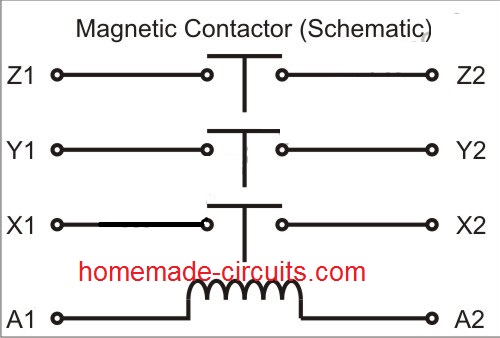
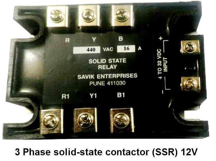
If you are unable to get the above 12V electromechanical relay/contactor, you can go for a 3 phase SSR contactor instead, as shown below.
