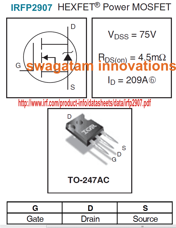
In this post I have explained the main features datasheet of high current N-Channel mosfet IRFP2907 which is rated to handle up to a staggering 209 amps of continuous current at a reasonably massive 75 volts.
High Current Specs
With the advent of mosfets, switching huge power through compact packages has become particularly feasible.
Take for example the proposed high current mosfet IRFP2907 (has no relation to 2N2907) which could be used for switching currents exceeding 200 amps, exclusively suitable for wind turbine generators. application
Although this device is designed specifically for automotive applications, the extreme range of this device can be effectively employed for many other applications such as inverters, wind turbines, soar inverters etc.
Precisely, this N-Channel device would be ideally suited for wind turbine inverter applications since this application incorporates alternators which is an automotive component.
Main Specifications and Features

I have explained about the main features of the mosfet IRFP2907
- Advanced Process Technology: ensures a rugged foolproof design and operation parameters.
- Ultra Low On-Resistance: allows optimal delivery of the source current across the load thereby enhancing the overall efficiency of the system.
- Dynamic dv/dt Rating: makes the unit extremely desirable with high power critical systems.
- 175°C Operating Temperature: this extreme range allows better sustaining, and consistency even under stressful operating conditions
- Fast Switching: Makes the device specifically suitable for rapid high current switching applications without the fear of device breakdown yet with maximum efficiency.
- Repetitive Avalanche Allowed up to Tjmax: Avalanche current is no more an issue with this device which is well guarded to make it completely failproof even under worst case scenarios.
Technical Datasheet
The Datasheet of the High Current Mosfet IRFP2907 may be understood with the following points:
- Extremely Low RDS(on) = Typically around 4.5 milliOhm, that's almost zero resistance across the drain and the source terminals when the device is fully saturated.
- Saturating Voltage = The saturating voltage VGS is around 10V which may be exceeded to not more than 20V. Applying this range of voltage across the gate and the source terminals would allow full saturation and almost zero resistance across the drain/source terminals.
- High Switching Current: With the above parameters applied, the maximum allowable current across the drain and the source terminals would be anything up to 200 amps....that's huge.
- Breakdown Voltage = It should not be exceeded preferably above 70 volts. This is applied across the drain and the source with a load in series at current levels that may exceed the 200 amp mark, as explained above.