The simple configuration of a transformerless power supply circuit presented below is able to provide high current at any assigned fixed voltage level. The idea seems to have solved the problem of deriving high current from capacitive power supplies which earlier seemed a difficult proposition.

Introduction
I have discussed a few transformerless power supply circuits in this blog which are good only with low power applications, and tend to become less effective or useless with high current loads.
The above concept utilizes high voltage PP capacitors for dropping the mains voltage to the required level, however it is unable to raise current levels as per any desired particular application.
Although, since the current is directly proportional to the reactance of the capacitors, means the current can be lifted just by incorporating more capacitors in parallel.
But this puts a risk of high initial surge currents which might destroy the involved electronic circuit instantly.
Adding Capacitors to Increase Current
Therefore adding capacitors might help to increase the current specs of such power supplies but the surge factor must be first taken care of for making the circuit feasible for practical usage.
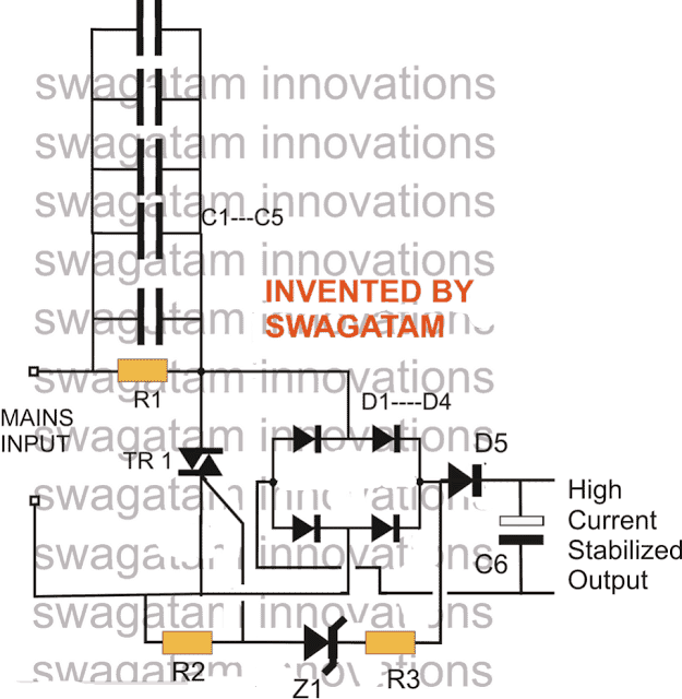
The circuit of a high current transformerless power supply explained here hopefully, effectively handles the surge developing from power transients such that the output becomes free from the dangers, and provides the required current supply at the rated voltage levels.
Everything in the circuit is kept just as its old counterpart, barring the inclusion of the triac and zener network which actually is a crowbar network, used for grounding anything that goes above the rated voltage.
In this circuit the output would hopefully provide a stable voltage of around 12+ volts at around 500 mA of current without the dangers of any accidental voltage or current influx.
CAUTION: THE CIRCUIT IS NOT ISOLATED FROM MAINS AND THEREFORE INVOLVES HIGH RISK OF ELECTROCUTION, APPROPRIATE PRECAUTION NEEDS TO BE EXERCISED.
UPDATE: A better and a more advanced design can be learned in this zero crossing controlled surge free transformerless power supply circuit
Parts List
- R1 = 1M, 1/4W
- R2,R3 = 1K, 1/4 WATT
- C1----C5 = 2uF/400V PPC, EACH
- C6 = 100uF/25V
- All DIODES = 1N4007
- Z1 = 15V, 1 watt
- TRIAC = BT136
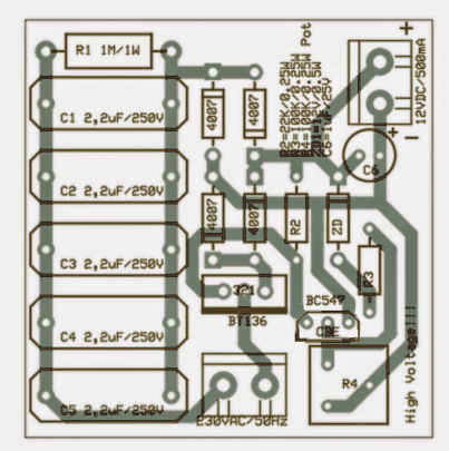
A neatly drawn PCB for the above high current transformerless power supply may be seen below, it was designed by Mr. Patrick Bruyn, one of the avid followers of this blog.
Update
A deeper analysis of the circuit showed that the triac was dumping a significant amount of current while restricting the surge and controlling the current.
The approach taken in the above circuit for controlling voltage and the surge is negative in terms of efficiency.
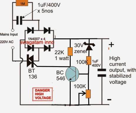
In order to obtain the intended results as proposed in the above design and without shunting precious amps, a circuit with exactly opposite response needs to be implemented, as shown above
Interestingly, here the triac is not configured to dump power rather it's wired in a such a way that it switches OFF power as soon as the output reaches the specified safe voltage limit, which is detected by the BJT stage.
New Update:
In the above modified design the triac may not conduct properly due to its rather awkward positioning.
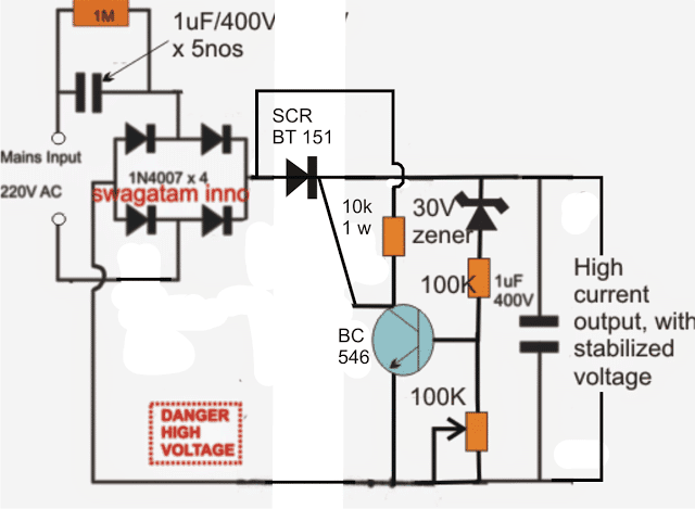
The following diagram suggests a correctly configured version of the above, which can be expected to operate as per the expectations.
In this design we have incorporated an SCR instead of a triac since the positioning of the device is after the bridge rectifier and therefore the input is in the form of a DC ripples and not AC.
Improving the above design:
In the above SCR based transformerless power supply circuit, the output is surge protected through the SCR, but the BC546 is not protected.
In order to ensure a complete protection for the entire circuit along with the BC546 driver stage, a separate low power triggering stage needs to be added to the B546 stage. The amended design can be seen below:
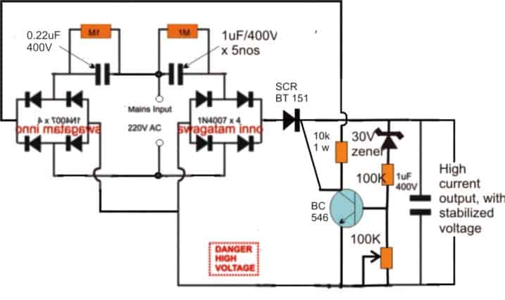
The above design can be further improved by modifying the position of the SCR as shown below:
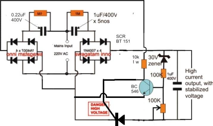
So far we studied a few transformerless power supply designs with high current specs, and also have learned regarding their different modes of configurations.
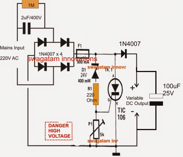
Below we would go a little farther and learn how to make a variable version circuit using an SCR. The explained design not only provides the option of getting a continuously variable output but is also surge protected, and therefore become much reliable with its intended functions.
The circuit can be understood from the following description:
Circuit Operation
The left side section of the circuit is quite familiar to us, the input capacitor along with the four diodes and the filter capacitor forms the parts of a common, unreliable fixed voltage transformerless power supply circuit.
The output from this section will be unstable, prone to surge currents, and relatively dangerous to operate sensitive electronic circuits.
The portion of the circuit on the right side of the fuse transforms it into a completely new, sophisticated design.
The Crowbar Network
It's in fact a crowbar network, introduced for some interesting functions.
The zener diode along with R1 and P1 forms a kind of voltage clamp which decides at what voltage level the SCR should fire.
P1 effectively varies the zener voltage from zero to its maximum rating, so here it an be assumed to be zero to 24V.
Depending upon this adjustment, the firing voltage of the SCR gets set.
Supposing P1 sets a 12V range for the SCR gate, as soon as mains power is switched ON, the rectified DC voltage starts developing across D1 and P1.
The moment it reaches the 12V mark, the SCR gets sufficient triggering voltage and instantly conducts, short circuiting the output terminals.
The short circuiting of the output tends to drop the voltage toward zero, however the moment the voltage drop goes below the set 12V mark, the SCR is inhibited from the required gate voltage and it reverts to it non conducting state.... the situation yet again allows the voltage to rise, and the SCR repeats the process making sure the voltage never goes above the set threshold.
The inclusion of the crowbar design also ensures a surge free output since the SCR never allows any surge to pass through to the output under all circumstances, and also allows relatively higher current operations.
Circuit Diagram
Another SCR based Circuit
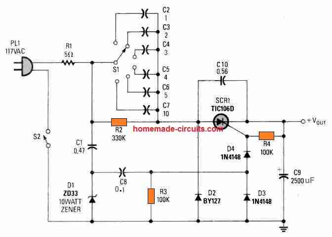
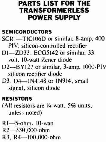
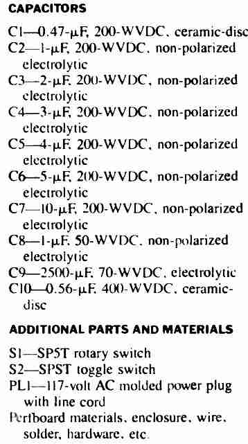
This SCR based high current Transformerless Power Supply consists of rather a few, easily accessible electronic parts.
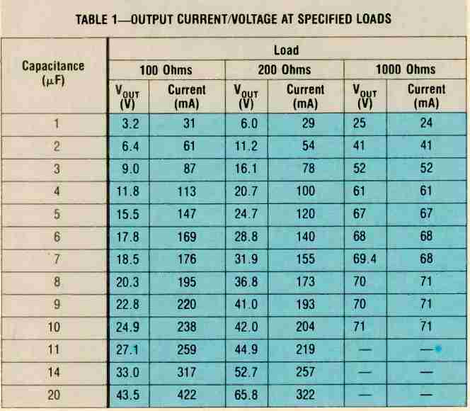
The output voltage level (and also the level of feasible current as provided in the Table I) is adjustable by rotating the rotary switch S1.
Table#1
Zero Crossing Controlled High Current Transformerless Power Supply Circuit
The following circuit shows how a zero crossing concept can be implemented to create an effective transformerless high current power supply circuit, which is highly customizable.
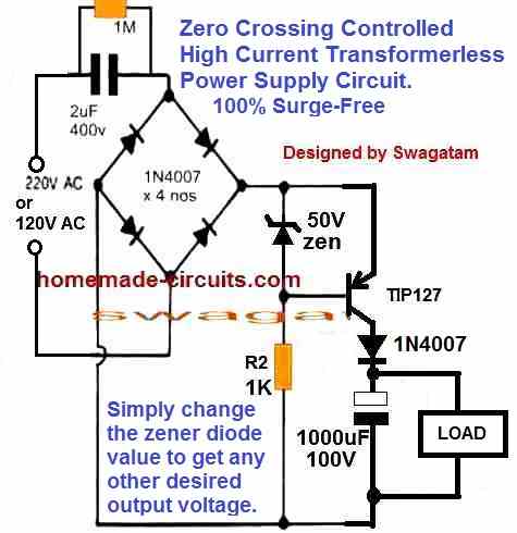
Advantages of this Circuit are as follows:
100% surge free ensures that the load, zener diode and the capacitor are completely safe all the time regardless of the input switching conditions of the power supply.
No heat dissipation ensures that the circuit's efficiency is maximum.
How the Circuit Works
We know that the main issue with transformerless power supply circuit is the switch ON surge current, which happens due to the sudden peak AC entering the electronic circuit connected with the power supply.
This sudden in-rush voltage and current leads to the burning of the vulnerable electronic components attached with the power supply.
This means that, if the load is allowed to be switched ON whenever the AC waveform nears the zero crossing then such mishaps can be avoided.
The above circuit does exactly this.
The PNP TIP127 conducts only when the AC waveform is below the zener value.
When the TIP127 conducts the AC waveform is already within the safe range of the load and this safe voltage gets stored in the 1000uF capacitor for powering the load.
The process continues for each cycle and only when the AC peak has dropped down safely to the zener value, which keeps the load powered consistently, with an optimized voltage and current inputs.

Purpose of the 1uF 400V cap at output in the last update.
It is positioned to absorb possible high voltage spikes entering the output side
Thanks
Thanks
Dear Swag,
Can I use BTA06 6A 600V TRIAC in place of BT151?
Yes you can use a triac also it won’t have any negative effects…
hi sir for the similar kind of circuit in am getting 30 ma current output i am using the 105j(1uf) capacitor but i want to drive high load so i need more than 500ma is it better to add another 4 r 5 105j caps in parallel to each other
Hi Sanjeev, yes you can add more capacitors in parallel to get higher current, each 105 capacitor would give you at least 50mA.
but make sure to add the triac controller as explained in the above article to control surge currents, and regulate voltage.
hai sir
Can you please suggest me a circuit for making 50v 10amp power supply
Hi Richards, you mean using the above concept?
hai sir
No sir, I am using.
Is above circuit works to produce 10amps of current.
Richards, for 10 amps you must use a transformer, the above concept may work but is strictly not recommended…..
you can try the following concept instead
https://www.homemade-circuits.com/2012/01/how-to-make-versatile-variable-voltage.html
ok sir thank u
Sir, how much power a transformer with the following specs can give ?
230/14-0-14 5A
Will it be 14×5=70 W or
(14+14)×5= 140 W ??
It is 70 watt
hello sir i want to switch 12v dc relay, using capacitive power supply but my zener diode is become over heat.
so please solve my problem..
Hello Devkaran, for a relay you won’t require a zener, you can connect it directly with the DC from the capacitive output…the relay coil is much stronger than a zener and will be be able to regulate the capacitive output safely without any external support. you can use a 105/400V caapcitor for the capacitive power supply
thanks for immediate reply sir,
but i am controlled the relay using pic12f675 micro controller. so micro controller have need pure dc and exactly 5v because i am using adc function and there is need to 5v .i am using 7805 voltage regulator for 5v.
OK, In that case you can use the 7805 for supplying the MCU, and connect the relay positive side directly with the capacitive bridge output.
I hope you have understood the configuration….and also be cautioned regarding the dangers involved with a capacitive PS
can i replace bc546 with bc548 transistor
and bt151 with TYN612M SCR.
No that won’t do, BC546 cannot be replaced with BC548, and BT151 is specifically recommended for this design
ok sir thank you very much for this help.
you are welcome!
hello sir the system is performing but my bc546 has blown up and now going to replace with another and will update you. thanks
with 10K resistor in series the BC546 shouldn’t have blown, anyway you can try connecting a 15V zener between the gate of the SCR and the emitter of BC546, this will hopefully solve the issue..
hello sir i get a fixed voltage of 5v at the output. the 1M resistor fixes it to give only 5volts yet i want 14volts at the output
Olupot, the 1M has no relation to the output, the current will pass through the input capacitor, the 1M is only to ensure correct discharging of the capacitor when the circuit is unplugged from the mains….
you can try the following concept if you are finding the above difficult.
https://www.homemade-circuits.com/2016/07/scr-shunt-for-protecting-capacitive-led.html
Many thanks for quick and clear reply dear Swagatham.
you are welcome Anil!
Hi Swagatham
I will use TL431 based voltage regulator with power transistor for high current handling.
I have seen many rechargable tourches, Emergency lights, LED display circuits use capacitor based simple powersupply. Those work very effectively without any protection circuits such as SCR, TRIAC, Thermister, Zero-crossing circuit….etc. So, is it neccessorry a surge/spike protection circuit…..? If, yes, which circuit would be morethan 75% effective. Just provide link of that circuit.
Probably, it should be Zerocrossing circuit.
Thanks in advance.
Hi Anil, emergency light circuits use capacitor based power supply for charging battery at a very low current rate, therefore the protection stage is not included, still they do use a zener diode for regulation.
you can use power transistor also, but a single SCR or triac handles everything perfectly and reliably, without depending on any special ICs or costly surge protection devices, and a SCr/triac suits better for high voltage circuits than power transistor.
for zero crossing concepts you can refer to this page
https://www.homemade-circuits.com/?s=zero+crossing+power
Hi Swagatham,
I have successfully assembled few capacitive powersupplies for illuminating one or two 20mA leds as nightlamps. I used 474pf, 630V, polyster capacitors. I always use a proper value zener diode at output for voltage regulation.
My doubt, is it suitable, capacitors that use with seiling fan….(usually it’s value is 2.5mfd 400vac) for this type of powersupply….?
Hi Anil, yes it is OK to use fan capacitor also, it is the 400V rating that is important, but make sure that the zener wattage is proportionately upgraded as the microFarad is increased
gud day sir am working on my circuit but i got some things i want you to clarify
1 the orignal circuit had a 100uf/25v and yet this circuit am making has a ppc rated 1uf/400v at the output so i need some help there.
2 what is the function of the 100k pot thanks alot
Hi Olupot, 1uF/400V is not necessary, you can replace it with a 100uF but make sure the voltage rating is twice of the intended output level.
100k pot can used for raising the output voltage to higher limits than the zener value.
good morning sir i apreciate the good work you do thanks alot. i have a question regarding the circuit is it possible for me to increase the output current to around 800mAand also can i use it to charge my small batt of 12v 7Ah.
Hi Oluput, that may be possible, but the triac can get immensely hot, you a replace the shown 1 amp with a 3 amp triac, then it would be fine.
yes you can use it to charge a battery, however the above concept is not isolated from mains, therefore touching the wiring with hand can give a fatal shock…therefore it's not recommended for such applications which may not be covered.
hello sir thanks for the great work. i take time to study each and every circuit you post that i find am in need of.so i have some question regarding this circuit
1. can i get up to around 800 to 900mA from the circuit.
2. is it possible to use this circuit to charge a small motorcycle batt of 12v/7Ah. i wil be greatful if i get it done for my small work bench thanks have ablessed day
Thanks Daniel,
yes you can use it to charge a battery, however the above concept is not isolated from mains, therefore touching the wiring with hand can give a fatal shock…therefore it's not recommended for such applications which may not be covered.
Please answer my query….
The word "below" was mistakenly mentioned, it should have been "above"…I have corrected it and also posted a new modified and technically more correct version of the same. you can check it out at the end of the post.
The opto coupler version is not updated because an opto could make the design unnecessarily complex and an overkill…
Referring to your article
"In order to obtain the intended results as proposed in the above design and without shunting precious amps, a circuit with exactly opposite response needs to be implemented, as shown below:""
their is no circuit below these lines??
someone in comments referred to circuit with optocoupler ,but in this post there is no cct involving optocoupler…..
please point out the updated circuit resulting high current and stable voltage…….
thanx in advance……carry on the good work.
In order to obtain the intended results as proposed in the above design and without shunting precious amps, a circuit with exactly opposite response needs to be implemented, as shown below:
where is the cct in article ?? there is only one cct under update heading???
which cct is the right one ,and will not dump amperes…..??
obviously, the circuit design shown under the update is the one which is being discussed in that section.
both are correct it depends which you feel is better.
what ampere in trafo 220vac? and out ?
Hi Swagatam!
Have you tested that last circuit with the BC546? because I took a look at it and thought: "the triac is iniatially not conducting, to conduct I need a pulse on it, and to have a pulse with some enough current to make it start conducting, I need that current flows through the diodes bridge, but how this could happen if the triac is not conducting? It seems that I need to give a "little push" at the gate's triac in order to it start conducting and after that have my BC546 in open state and therefore applying the collector voltage and consequently a current flowing through the triac's gate".
The point is, there is no current flowing through the circuit at all until the triac starts conducting, but is depends on the circuit ahead it and the circuit ahead the triac depends that triac starts conducting… At programming we call that deadlock…
thanks Swagatam!
Hi Thiago, the last circuit is just a suggestion, it has not been tested by me yet.
yes, to initiate the BT136 some form of arrangement would be required, you can connect another 1uF/400V in parallel with the triacs MT1/MT2 or a 1K 1/4 watt resistor also could be tried.
Or two push buttons, one in parallel with MT1/MT2 in order to give that little push I commented and turn the power supply on, and another one in series with the gate in order to cut off the pulse on the triac and switch off the power supply. Maybe it could be a nice solution.
I liked very much your design and I think of implementing it with what I said. I don't want to have a transformer on my project…
Thanks again Swagatam!
thanks thiago, s push button with MT1/MT2 might not work because at the first zero crossing the triac will tend to switch OFF, shutting of the whole circuit.
a capacitor or a 1K resistor as suggested by me earlier could be the only solution.
anyway you can try both the solutions and see which one works more appropriately.
however the above issue could be corrected by adding a high value capacitor instead of the 1uF shown at the output side of the design….
Yes, maybe it could not work, I will simulate both approachs at proteus and I come back to you to let you know the results. Thanks again!
hello
i want to drive 12vRelay @ 30 ma with this method . Also want to add MOV .pl help which value of MOV i go with ? .
the above circuit won't be required, you can use the following simple design
https://www.homemade-circuits.com/2011/12/cheap-yet-useful-transformerless-power.html
replace the 50 ohm resistor with a 5 OHm NTC themister
Is it possible to light up 20 watt led with this circuit?
it can be used
To convert it into 5v power supply do we need to need to replace only the zener diode or some replacements are required too?
only the zener diode will need to be replaced
Hi 🙂
I want to make 12V 2A transformer less power supply. can u help me? please.
because your given circuit doesn't provide much current.
Thank you
Hi, for 2amp a capacitive power supply is not recommended, you may have to build an SMPS for that
can i use this circuit for laptop adapter(20V,5.0A)
NO…
sir what is efficency of above ckt and how can we increase it???
Not sure, did not calculate it.
Hi,
Its possible to get 0-400VDC of 2A ???
Hi, it is possible, but for 2 amp the triac will need to be rated at 6 amps
Hi,
How can get high voltage (0-400V) with 2A current ?
Hi Swagatam,
Im just starting to find/search for a small low cost PS for driving ESP8266 boards, where the requirement is 5V or 3,3V with 350-500mA and found that your site have the most info about these transformerless PS, but I am confused after looking at all the differet diragrams on your site, so my questions is you have such a diagram on your site and can send post the link ? .. if not, which diagram will be best and what changes are needed ?
thx in advance for your support.
PS input would be 220Vac – 50hz
Hi Allan, I think you should try the following design:
https://www.homemade-circuits.com/2014/02/220v-smps-cell-phone-charger-circuit.html
Dear Swagatam Majumdar,
Greetings !!!!
I need 5v 1ahm output AC to DC transformer less circuit, if you can make this circuit in past, please send the details following email id :
mu2003777@gmail.com
09586516661, 09898586746
i am waiting for your answer !!!!
Dear Mahesh,
for 1 amp current it is advised to go for a SMPS design as explained in the following article:
https://www.homemade-circuits.com/2014/02/220v-smps-cell-phone-charger-circuit.html
Dear Sir,
If i change the zener diode to 15V, do you think the voltage will follow, how about the current? how much current it will give? the current will depend only to the zener or to the 5x capacitor in the input.? thanks
odie
Dear Odie,
yes the output voltage will change according to the zener value.
current will depend on the input capacitor value.
Sir is this your finalized circuit for the high current transformerless power supply
3.bp.blogspot.com/-Y7aCY8rtB44/U_cx5MAANjI/AAAAAAAAIDE/Xj–z257fYU/s1600/efficient%2Btransformerless%2Bpower%2Bsupply%2Bcircuit.png
i am getting no dc output from this circuit.. how can you trigger the traic with a DC control signal without using an optocoupler… and please tell me how to configure the circuit to get the output voltage
RT, a triac can be fired from any DC source, an opto coupler is used only when the triac stage needs to be isolated from the DC stage, otherwise it is not essential.
please check your circuit carefully there could be some mistake in it.
Have you verified the circuit? Please confirm.
Thanks.
Ok..sir,
Thank you..
you are welcome, you can also think about becoming a paid contributor to this site by submitting circuit related projects and concepts…..
Oh, sorry sir, actually at first I could not find your answer….
But sir,
is not possible to make transformer less 15V, 3Amp DC power supply ?
Narottam, transformerless can be in the form of SMPS, capacitive type is not recommended for such high current…the best is transfomer type which is the most reliable.
Sir,
I want to make 15 volt, 3 amp DC power supply in this process for giving the power supply of the project of "wireless cellphone charger" please help me with your advice that which components or value of components will be the change fo making it ?
And one more question, here the wattage of the resistor R1 is 1/4 watt, is it sufficient ?
Narottam, I have already answered it please check the above comment.
Sir,
I want to make a DC power supply of 15 volt, 3 amp for the project of "Wireless Power Supply".
So please help me with your advice that what components will be the change for making it and which circuit is the best for this ?
And one more question, here the wattage of the resistance R1 is 1/4 watt is it sufficient ?
Narottam, you can make it by using an LM338 IC, you can easily find the circuit idea in the datasheet of the IC, or even in this website itself….you will need a 0-24V/5amp transformer for supplying the input to this IC regulator circuit
R1 is only for discharging the capacitor when the circuit is being plugged out of the socket…higher wattage is not required…1/4 watt is enough, moreover the value is 1M that's too high for any possible damage.
Hi Swagatam,
Based on this article How much current it will produced? Is the circuit is been tested? and what type of capacitor you used for this paralled caps.
Thanks & more power to your blog
Hi Odie, it can be used for generating up to 500mA without much heating of the triac…it's a tested design
all the capacitors must be metalized polyester type..
hi,
can i used electrolyte capacitor in series, with inverse polarity each other to substitute non polar dropper capacitor in your circuit, let say i use two 2.2uf/400V elco , arrange in series with opposite polarity
you can try it, technically it should work, but PPC type of capacitor is normally recommended in such applications.
Dear sir,
I want to makr a transformerless power supply to gain 12v 1-2A DC.
Please help me sir how can i do it…
Thank you..
Dear Malay, you must go for an SMPS based circuit instead of a capacitive one, which is never suitable for such high current applications.
Hello sir,
I want ti make a 12V 1-2A output,transformerless power supply.
Can you please help me sir how do i do this.
Hello Malay, you can try any of the designs presented in the following article:
https://www.homemade-circuits.com/2012/03/how-to-design-power-supply-simplest-to.html
how to converted 1amps please update sir
use 15 nos of 1uF/400V caps in parallel at the input and use a 6amp triac
Hi Mr. Majumdar,
Can I use this circuit for three phase input supply.
Input voltage will be ~440V, which will be phase to phase.
Hi Vikram, it could be possible if all the vital components are rated at 1kv or at least 700V
Thank you sir.
I have one query. There will not be any Neutral line. Input will be any 2 phases. i.e RY or YB or RB.
So is it possible.?
yes any phase from the 3 phase can be used with the above design….neutral may not be required. but I am not exactly sure about it? you may have confirm it practically.
hai i made the above circuit its working fine but the problem is when i connect 110vac its not working can you tell me the reason .
Hi, that's cannot be possible, any AC input higher than the zener voltage should work.
remove the triac connection and check again…
Can i use the above circuit for building a cell phone charger which will give 5V and 2.2A of current??
technically it may be possible, but strictly not recommended because the above design is not isolated from mains and is too crude and dangerous to be used as a cell phone charger
dear Swagatam,
it's good AC-DC converter. Can you explain more details transistor, triac stage?
when circuit work normally, current through zener, 100k resistor and 100k variable resistor about 10mA, voltage at base of NPN transistor about 1V cause open transistor. Therefore, voltage at G gate of triac about 0V, triac off => it's not logic, am i wrong??
hope your help!
thank you.
dear unknown, actually there should be a 1K 2 watt resistor across the triac MT1/MT2….so when power is switched ON, the circuit will switch ON with a low current via the 1K, and switch ON the triac for a full conduction with the rated current of the capacitor….however as long as 30V is not reached the transistor will not conduct, but when this happens the transistor will conduct and cut off the triac…this sequence will go ON very rapidly at microsecond rate, making sure that the output voltage never exceeds the 30V mark or above the zener voltage mark.
dear Swagatam,
Thank you very much, you're so enthusiastically.
I understand now.
you are welcome dear Ngan!
Dear Mr Majumdar,
Your electronic skill is superior. Thanks for showing everything with diagram.etc. My question is:
Do you have a schematic diagram of a transformerless power supply 220v AC in. and 3.3v 400mA DC out?
Thanks in advance Christer
Thanks Christer,
May I know for what application you are planning to use it?
Thank you for responding so fast. It is a project for school. Burglar alarm, and I'm using Arduino.
I need to supply with 3.3 v.
Thanks again
OK, in that case the following SMPS design could be recommended:
https://www.homemade-circuits.com/2014/02/220v-smps-cell-phone-charger-circuit.html
the zener at the output can be adjusted to achieve the required 3.3V instead of the shown 5V
a capacitive transformerless power supply could be dangerous, and therefore may not be recommended for your application
…By the way you can simply use you mobile charger for the purpose by adding a couple of 1N4007 diodes in series with the positive to get the same…
Do you think i can use this circuit for the 100W LED's? Because transformer 24V 3 amp they dont have here 🙁
No this circuit is not recommended for a 100 watt LED module.
ok, thanks, i am going to try to lower the winding's from the coil.
Capacitor increase so current increase i am right?????? Explain triac and zener function in 1 st circuit
yes that's correct
the triac grounds the excess voltage that surpasses the selected zener voltage level and thus maintains a constant voltage at the o/p
Hello Swagatam,
Thank you for publishing your design.
I made a PCB design of it with almost identical parts you suggested, but I cannot get it working. Could you please look at my design for what mistake I obviously made?
Thank you in advanvce!
PCB design: https://drive.google.com/file/d/0B8jhrSu-d9NHRVpEV1BhSjBKNzQ/view?usp=sharing
Thanks very much Patrick, I'll update the info in the above article soon…
In PCB by mistake Triac gate is connected with BC547( Emitter ) instead of Collector that is why circuit is not working, if I am not wrong. rotate NPN transistor 180 degree in PCB design software hope it will work.
OK thanks, I'll check it and correct it soon.
Hi,
Thanks for your reply.
I change the transistor and the overall layout. Could you guys please take a look if this looks oke?
Link: https://drive.google.com/file/d/0B8jhrSu-d9NHdk56eGd3U0tQNVk/view?usp=sharing
Thank again!
Again I build up this PCB but it just doesn't work. Can anybody take a look at my design and maybe tell me what I am doing wrong?
Thank you in advance!
Thank you madusanka, for any high watt LED it's always recommended to use an SMPS adapter, however you can also try the following circuit and see how well it performs:
https://www.homemade-circuits.com/2015/05/zero-crossing-controlled-surge-free.html
use 3 nos of 105/40v capacitors in parallel for the input capacitor in order to get at least 200mA current at the output