In this post I have explained a high efficiency 1.5 V to 4.2 V LED driver circuits which can be used with a standard Li-Ion battery for enhanced illumination, extended battery backup and long battery life.
Main Features
- Low input voltage between 1.5 V and 4.2 V.
- As many as 16 LEDs can be driven.
- Constant Current for the LEDs, meaning longer life for the LEDs.
- Guaranteed Perfect White Light from the LEDs, with no shift in the white color, regardless of the battery voltage.
- Long Battery backup time and extended battery life.
- LEDs fully protected against over voltage and over current scenarios.
- PWM dimming feature.
- LEDs may remain illuminated until it has sucked the last drop of energy from the battery.
Using IC LT1932
The IC LT1932 is a fixed frequency step-up DC/DC converter intended to function as a constant-current source. The LT1932 is perfect for configuring Li-Ion Battery LED drivers, wherein the LED brightness corresponds strictly to the current flowing through them and not the voltage across their pinouts.
The device can accept input from many different kinds of sources via a voltage range of 1V to 10V.
Battery-powered designs are significantly simplified by the LT1932's ability to correctly regulate LED current regardless of whether the input voltage is higher than the LED voltage.
LED current could be readily modified using both a DC voltage or a pulse width modulated (PWM) signal after setting it within 5mA and 40mA by simply adjusting an external resistor.
Absolute Maximum Rating of LT1932 IC
- VIN = 1.5V to 10V
- SHDN, Shutdown Voltage = 10V
- SW, Switched Voltage = 36V
- LED Voltage = 36V
- RSET Voltage = 1V
- Junction Temperature = 125°C
- Operating Temperature Range = -40°C to 85°C
- Storage Temperature Range = 65°C to 150°C
- Lead Temperature (Soldering, 10 sec) = 300°C
Pinout Details
SW (Pin 1): Switch Terminal. This corresponds to the collector of the internal NPN power switch. To reduce electromagnetic interference (EMI), it's advisable to minimize the extent of the metal trace connected to this pin.
GND (Pin 2): Ground Connection. Directly link this pin to the local ground plane.
LED (Pin 3): Light Emitting Diode Terminal. This serves as the collector for the internal NPN LED switch. Connect the cathode of the lower LED to this pin.
RSET (Pin 4): Adjust LED current by introducing a resistor between this pin and ground, controlling the current flowing into the LED terminal. This pin also facilitates LED dimming.
SHDN (Pin 5): Shutdown Input. To activate the LT1932, establish a connection to this pin with a voltage exceeding 0.85V; for deactivation, connect it with a voltage below 0.25V.
VIN (Pin 6): Input Power Connection. Enhance the bypassing of this pin by incorporating a capacitor to ground as close to the device as feasible.
Basic Operation
The LT1932 employs a constant frequency and current mode control strategy for maintaining the output current, denoted as ILED. Understanding its operation is best facilitated by referring to the following Figure 1 block diagram.

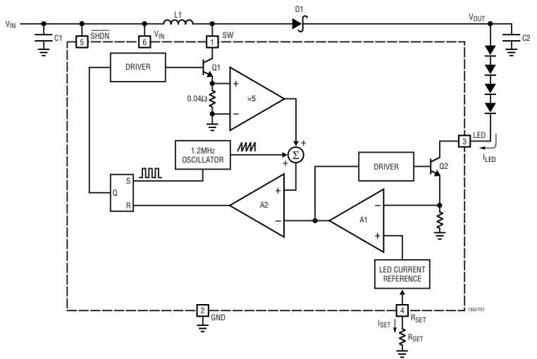
At the onset of each oscillator cycle, the SR latch is activated, initiating the operation of power switch Q1. The signal at the non-inverting input of the PWM comparator A2 is directly proportional to the switch current.
It is then combined with a segment of the oscillator ramp. Once this signal reaches the threshold established by the output of the error amplifier A1, comparator A2 resets the latch and deactivates the power switch.
In this manner, A1 establishes the correct peak current level to ensure the regulation of LED current.
Should the output of A1 rise, more current is supplied to the output; conversely, a decrease in A1's output results in less current being provided. A1 monitors the LED current through switch Q2, comparing it to the current reference, which is established by configuring resistor RSET.
The voltage at the RSET pin is maintained at 100mV, and the output current, ILED, is controlled at a level of 225 times ISET.
Pulling the RSET pin above 100mV will cause a reduction in the output of A1, leading to the deactivation of power switch Q1 and LED switch Q2.
Li-Ion LED Driver Application
As discussed earlier, the LT1932 is a step-up DC/DC converter, with a fixed frequency output, and is specifically designed to produce a constant current output.
Since the device is able to directly regulate the output current, it becomes perfectly suitable for driving light emitting diodes (LEDs).
The IC makes sure that the LED illumination is dependent on the constant current flowing through the LED and not the varying voltage subjected across their terminals.
The main objective is to create high efficient LED drivers using Li-Ion battery, ensuring an extended battery life, and long backup time.
Setting up LED Current
The LED current can be configured using a solitary resistor that connects to the RSET pin, as illustrated in Figure 1 above.
The RSET pin is internally controlled to maintain a voltage of 100mV, effectively setting the current exiting this pin, denoted as ISET, to be equal to 100mV divided by the value of the resistor (RSET).
To maintain precise regulation, it is advisable to utilize a resistor with a tolerance of 1% or better.
The following table provides examples of several typical RSET values with a 1% tolerance.
| ILED (mA) | RSET VALUE |
| 40 | 562Ω |
| 30 | 750Ω |
| 20 | 1.13k |
| 15 | 1.50k |
| 10 | 2.26k |
| 5 | 4.53k |
For different LED current requirements, you can employ the following formula to determine the appropriate resistor value.
RSET = 225 x (0.1V / ILED)
The majority of white LEDs are typically operated at peak currents ranging from 15mA to 20mA.
In more high-power configurations, designers may employ two parallel sets of LEDs to achieve increased brightness, resulting in a current flow of 30mA to 40mA (equivalent to two sets, each operating at 15mA to 20mA) through the LEDs.
Typical Application Circuit
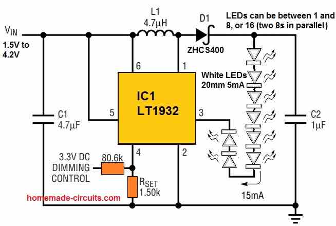
The following figure 2 shows the basic application circuit for driving 8 LEDs through a single 3 V or 4.32 V Li-Ion cell.
Protection against Open Circuit
The LT1932 can be protected by connecting a zener diode in parallel with the LEDs in cases wherein the LED chain might be unplugged or could become an open circuit (see Figure 3 below for further information).
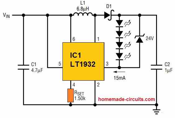
When the device is turned on without any LEDs, the LED pin does not send any current feedback to the device.
The LT1932 thus runs at its highest duty cycle, producing an output voltage which can be 10 to 15 times greater than the input voltage.
Without the zener diode, it is possible for the SW pin to encounter voltages greater than 36V, breaching its maximum rating.
For proper protection, please make sure the zener voltage is rated higher than the LED string's maximum forward voltage.
PWM Brightness Control
PWM brightness control offers an extensive dimming range, exceeding 20:1, achieved by alternately pulsing the LEDs on and off through the control signal.
The LEDs operate either at full current or zero current, but the average current varies in accordance with the duty cycle of the PWM signal, which typically falls within the range of 5kHz to 40kHz.
When implementing PWM dimming with the LT1932, there are two available approaches (refer to Figure 4 below).
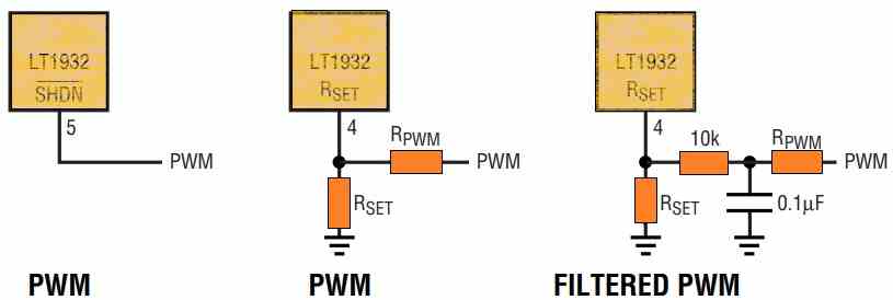
Firstly, the SHDN pin can be directly manipulated, where an increase in the duty cycle results in heightened LED brightness.
With this method, the LEDs can be dimmed or completely switched off using the same control signal. Setting the signal to 0% duty cycle deactivates the LT1932 entirely, reducing the overall quiescent current to zero.
Alternatively, if the RSET pin is used for PWM dimming, an approximate value for RPWM can be determined using the following formula, where VMAX represents the "high" value of the PWM signal.
RPWM = RSET x (VMAX / 0.15V - 1)
PWM brightness control not only offers a wide dimming range but also consistently preserves an extremely authentic white LED color across the whole dimming range.
A white LED's authentic color changes depending on its working current and achieves an absolute white hue at a certain forward current, usually between 15 and 20 milliamperes.
When this value is deviated from, either higher or lower, the emitted light begins to take on a blue tinge. This shift frequently causes an unfavorable, observable blue tint on color LCD displays, which is unwanted.
As shown in Figure 4 above, once a PWM control signal is used to drive the LT1932's SHDN pin, the LEDs switch on and off at the PWM frequency rate.
The average current varies with the duty cycle as a result of this switching, which alternates the current between operating at full capacity and completely ceasing.
Due to this dynamic functioning, the LEDs are always powered at the exact current level required to generate the cleanest white light while they are in use.
Figure 5 illustrates the behavior of the LED current when the LT1932 is used in conjunction with a 5kHz PWM dimming control signal.
The PWM control signal is closely followed by the LED current waveform with no delays, which causes the LED brightness to vary linearly as the PWM duty cycle varies.
LED Brightness Control with a DC Voltage
In certain scenarios, a favored approach to regulating brightness involves employing a variable DC voltage for LED current adjustment.
Referring to the following figure, when the applied DC control voltage is raised, it induces a flow of current through RADJ into RSET, resulting in a reduction of the current exiting the RSET pin, consequently lowering the LED current.
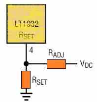
The selection of RADJ value should follow the guidelines below, with VMAX representing the highest DC control voltage, ILED(MAX) denoting the current set by RSET, and ILED(MIN) representing the minimum ILED value when the DC control voltage is at VMAX.
RADJ = 225 x {VMAX - [0.1 / ILED(MAX) - ILED(MIN)]}
Reference: LT1932 Datasheet
Need Help? Please Leave a Comment! We value your input—Kindly keep it relevant to the above topic!