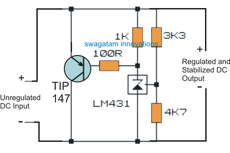
The high power "zener diode" circuit using transistor shunt regulator presented here can be used for obtaining a highly accurate, temperature and voltage stabilized outputs from high current sources, safely.
Normal Zener Limitation
The low power zener diodes that we normally use in electronic circuits are specified to work with low currents, and therefore cannot be used for shunting or stabilizing high current supplies.
Although higher rated zener diodes are available, these could be relatively expensive. Nonetheless, it is actually possible to make a customizable high power zener diode using a power transistors and a shunt regulator IC as shown below:
Circuit Diagram

Using a Shunt Regulator
Looking at the figure we can see the involvement of a specialized shunt regulator IC in the form of LM431 or TL431, which is basically a low power adjustable zener diode.
Apart from the variable voltage attribute, the device also includes the feature of producing a temperature stabilized output, meaning ambient temperature conditions is not going to influence the performance of this device, which is not possible with the ordinary diodes.
But as far as power handling capacity is concerned the TL431 device is no better than the conventional zener diode counterpart.
However when it is combined with a power transistor such as the shown TIP147, the unit gets transformed into a highly versatile high power zener diode unit, capable of shunting and stabilizing high current sources without getting damaged.
Example Application
A classic application example of this circuit can be visualized in this motorcycle shunt regulator circuit where the design is employed for shunting and safeguarding the motorcycle alternator from the high reverse EMFs.
The design can be also tried in high current capacitive power supplies for acquiring surge free stabilized output from these rather unsafe but compact transformerless power supplies.
Other suitable applications of this versatile circuit could be for controlling windmill outputs and as electronic load controller for regulating hydro-generators outputs.
Without the TIP147 integration, the LM431 stage looks pretty vulnerable, and also the regulation being developed only across the anode/cathode of the device rather than across the main supply terminals.
High Power Control
With the power transistor integrated the scenario changes completely and now the transistor simulates the shunt regulator's results, shunting the high current from the input to the correct levels, as specified by the LM431 configurations.
The potential divider made by using the 3k3 and the 4k7 resistors at the reference input of the IC essentially determine the triggering threshold for the IC, typically the upper resistor can be tweaked for getting any desired zener stabilized voltage output from the transistor circuit.
The detailed calculations for the resistors may be learned from this TL431 shunt regulator datasheet
Note: The TIP147 must be mounted on a substantially big finned type heatsink for enabling a proper and an optimal functioning of the circuit.