The presented circuit offers an adjustable constant current source capable of reaching up to 60mA, operating at voltages as high as 350V.
Circuit Description
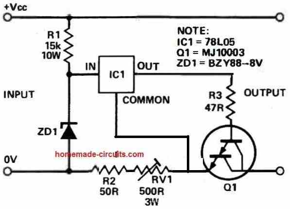
The input stage, consisting of resistor R1 and zener diode ZD1, delivers 8V to the regulator (a 7805), maintaining this voltage relative to its reference line.
This voltage level ensures sufficient power for the regulator's operation while minimizing excessive dissipation.
Function of the 7805 Regulator
The regulator's objective is to uphold a 5V potential difference between its output and common terminals, which is also applied to the base-emitter loop of transistor Q1.
Q1, configured as a Darlington device, exhibits a base-emitter voltage of approximately 1.5V when activated.
In case the load connected to the circuit's output causes the collector current to rise, the voltage developed across resistors R2 and RV1 will also increase.
Consequently, the voltage at the emitter of the transistor rises in relation to the 7805's common terminal.
During the conduction state of the transistor, its base voltage is compelled to increase.
Since the 7805 regulator maintains a constant 5V between its output and common terminals, the voltage drop across R3 will decrease, resulting in reduced base current.
This reduction counteracts the initial surge in collector current.
A similar mechanism comes into play when the collector current attempts to decrease.
The above working allows the circuit to behave like a high voltage constant current source.
Adjustable Current Feature
Facilitating current adjustment, the variable resistor RV1 is incorporated, while fixed resistor R2 serves to cap the maximum available current.
To handle power dissipation, a 3W wirewound type is recommended for the variable resistor.
Function of Darlington Transistor
The adoption of a Darlington transistor stems from its higher gain, leading to more consistent current flow.
The specific transistor used in this configuration boasts a rating of 400V and 150W at 25°C, ensuring safe operation within its specified limits.
Nonetheless, when a current demand surpasses a few milliamps, it's advisable to equip the Darlington transistor with a heat sink to mitigate potential temperature-related issues.
If desired, adjustments to the circuit values can be made to accommodate different voltage and current requirements, provided that the component ratings are not exceeded.
I pulled an OH SUNG squirrel cage fan vent out of an old microwave/convection oven. It is rated at 120 V 60Hz. Other markings show 128/105W, and 1.09/0.87A. Cap 7uF “Thermally Protected”.
I live in an apartment building built in 1947 which has steam heat. My thought was to attach a passive thermostat to the circuit that energizes and starts the fan when the steam heat begins and de-engergize when it cools. By running this fan under the radiator I can significantly gain more heat when the steam heat is present.
The wire harness has five wires. There is a diagram which I can’t seem to post an image of here. However, it can be seen here in this ebay post: " rel="ugc">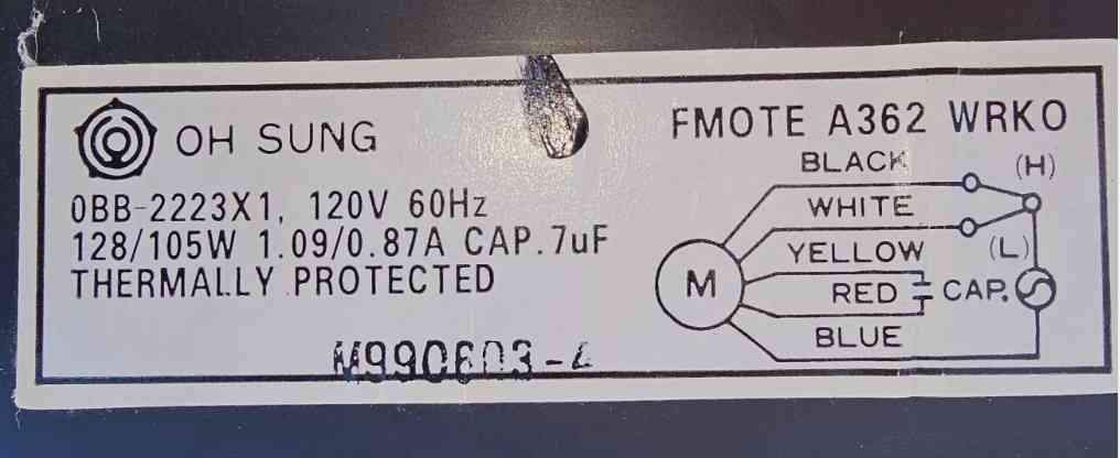
I don’t understand why there are five wires (black, white, yellow, red, blue). If I simply want to apply 120V AC current, which is hot and which is neural? What are the other three wires for? Can I use them to my advantage, like maybe to control fan speed based on the thermostat’s state? In any event, a simple on/off based on a hot thermostat would be a great outcome. Thank you kindly for any insights you can offer.
Looking at the image, it seems the Blue wire is directly connected to one of the mains AC input supply, preferably the Neutral wire.
The 7uF capacitor is supposed to be attached between the Yellow and the Red wires.
Now the LIVE or the Phase of the 120V AC seems to be going through a relay or a thermostat switch to the black and the white wires.
You could initially try applying the 120V AC between the Blue and the Black wires through a 1 Amp FUSE and check the response.
Thank you, I will give it a try. From further research, I see the fan has a Hi and a Low setting.
Sure, no problem. For the H/L selection you can probably try an SPDT switch, or maybe the H/L switch is supposed to be an SPDT relay configured with the protection circuitry…
Are you certain about that 15K resistor? At 60 ma, that’s going to drop 900 volts! What is its purpose, other than to limit current?
Also, why the “0V”? If one end on the zener is grounded, this won’t work, will it? The 78L05 will just put out 5 volts relative to ground, right?
I want to use this as an anode load for a 12AU7 or 6SN7 vacuum tube at about 10 ma current.
You are right, the circuit has mistakes, but the 15k is OK, although it might get super hot.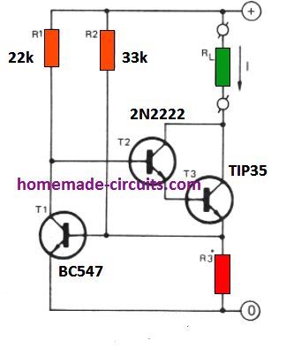
First of all the ground of the 78L05 must be connected to the emitter of Q1 and not directly to the ground line.
Moreover, the the 78L05 can be actually replaced with another BJT which will allow even higher value resistors to be used for R1. Higher resistor value would mean lower operating current and lower dissipation.
Here’s an example circuit which you can try instead of the above design. Please replace the transistors appropriately with higher voltage rated transistors.
" rel="ugc">