In this post we will try to learn how to diagnose and repair an inverter, by comprehensively learning the various stages of an inverter, and how a basic inverter functions.
Before I have explained how to repair an inverter it would be important for you to first get fully informed regarding the basic functioning of an inverter and its stages. In the following content I have explained regarding the important aspects of an inverter.
Stages of an Inverter
As the name suggests DC to AC inverter is an electronic device which is able to "invert" a DC potential normally derived from a lead-acid battery into a stepped-up AC potential. The output from an inverter are normally quite comparable to the voltage that is found in our domestic AC Mains outlets.
Repairing sophisticated inverters are not easy due to their many involved complex stages and requires expertise in the field. Inverters which provide sine wave outputs or the ones which use PWM technology to generate modified sine wave can be difficult to diagnose and troubleshoot for the folks who are relatively new to electronics.
However, simpler inverter designs that involve basic operating principles can be repaired even by a person who is not specifically an expert with electronics.
Before we move into the fault finding details it would be important to discuss how does an inverter work and the different stages normally an inverter may comprise:
An inverter in its most basic form may be divided into three fundamental stages viz. oscillator, driver and the transformer output stage.
Oscillator:
This stage is basically responsible for the generation of oscillating pulses either through an IC circuit or a transistorized circuit.
These oscillations are basically the productions of alternate battery positive and negative (ground) voltage peaks with a particular specified frequency (number of positive peaks per second.) Such oscillations are generally in the form of square pillars and are termed as square waves, and the inverters operating with such oscillators are called square wave inverters.
The above generated square wave pulses though are too weak and can never be utilized to drive high current output transformers. Therefore these pulses are fed to the next amplifier stage for the required task.
For info on Inverter oscillators you can also refer to the complete tutorial which explains how to design an Inverter from the scratch
Booster or Amplifier (Driver):
Here the received oscillating frequency is suitably amplified to high current levels using either power transistors or Mosfets.
Though the boosted response is an AC, it is still at the battery supply voltage level and therefore cannot be used to operate electrical appliances which work at higher voltage AC potentials.
The amplified voltage is therefore finally applied to the output transformer secondary winding.
Output Power Transformer:
We all know how a transformer works; in AC/DC power supplies it is normally used to step-down the applied input mains AC to the lower specified AC levels through magnetic induction of its two windings.
In inverters a transformer is used for similar purpose but with just opposite orientation, i.e. here the low level AC from the above discussed electronic stages is applied to the secondary windings resulting in an induced stepped up voltage across the primary winding of the transformer.
This voltage is finally utilized for powering the various household electrical gadgets like lights, fans, mixers, soldering irons etc.

Basic Principle of Operation of an Inverter
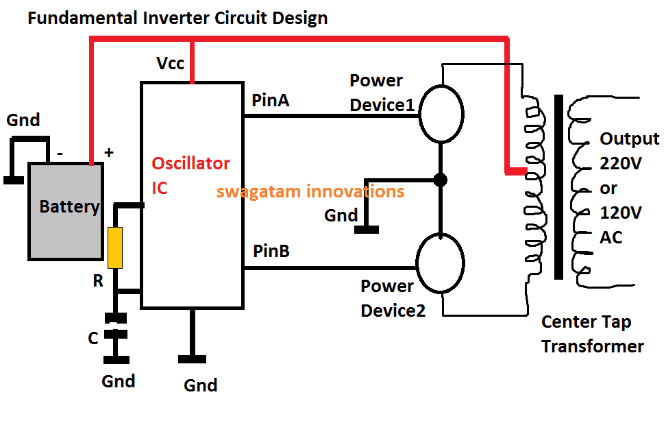
The above diagram shows the most fundamental design of an inverter, the working principle becomes the back bone for all conventional inverter designs, from the simplest to the most sophisticated ones.
The functioning of the shown design may be understood from the following points:
1) The positive from the battery powers the oscillator IC (Vcc pin), and also the center tap of the transformer.
2) The oscillator IC when powered starts producing alternately switching Hi/lo pulses across its output pins PinA and PinB, at some given frequency rate, mostly at 50Hz, or 60Hz depending as per the country specs.
3) These pinouts can be seen connected with the relevant power devices #1, and #2, which could be mosfets or power BJTs.
3) At any instant when PinA is high, and PinB is low, the Power Device#1 is in the conducting mode, while Power Device#2 is held switched OFF.
4) This situation connects the upper tap of the transformer to ground via the power device#1, which in turn causes the battery positive to pass through upper half of the transformer, energizing this section of the transformer.
5) Identically, in the next instant when the pinB is high and PinA is low, the lower primary winding of the transformer becomes activated.
6) This cycle repeats continuously causing a push-pull high current conduction across the two halves of the transformer winding.
7) The above action within the transformer secondary causes an equivalent amount of voltage and current to switch across the secondary by means of magnetic induction, resulting in the production of the required 220V or the 120V AC across the secondary winding of the transformer, as indicated in the diagram.
DC to AC Inverter, Repairing Tips
In the above explanation a couple of things become very critical for obtaining correct results from an inverter.
1) First, the generation of the oscillations, due to which the power MOSFETs are switched ON/OFF, initiating the process of electromagnetic voltage induction across the primary/secondary winding of the transformer. Since the MOSFETs switch the primary of the transformer in a push-pull manner, this induces an alternating 220V or 120V AC across the secondary of the transformer.
2) The second important factor is the frequency of the oscillations, which is fixed as per the country’s specifications, for example countries that supply 230 V, generally have a working frequency of 50 Hz, in other countries where 120 V is specified mostly work at 60 Hz frequency.
3) Sophisticated electronic gadgets like TV sets, DVD players, computers etc. are never recommended to be operated with square wave inverters. The sharp rise and fall of the square waves are just not suitable for such applications.
4) However there are ways through more complex electronic circuits for modifying the square waves so that they become more favorable with the above discussed electronic equipment.
Inverters using further complex circuits are able to produce waveforms almost identical to the waveforms available at our domestic mains AC outlets.
How to Repair an Inverter
Once you get well versed with the different stages normally incorporated in an inverter unit as explained above, troubleshooting becomes relatively easy. The following tips will illustrate how to repair DC to AC inverter:
Inverter is “Dead”:
If your inverter is dead, do preliminary investigations such as checking battery voltage and connections, checking for a blown fuse, lose connections etc. If all these are OK, open the inverter outer cover and do the following steps:
1) Locate the oscillator section; disconnect its output from its MOSFET stage and using a frequency meter confirm whether or not it is generating the required frequency. Normally, for a 220V inverter this frequency will be 50 Hz, and for 120V inverter this will be 60 Hz. If your meter reads no frequency or a stable DC, it may indicate a possible fault with this oscillator stage. Check its IC and the associated components for the remedy.
2) In case you find the oscillator stage working fine, go for the next stage i.e. the current amplifier stage (power MOSFET). Isolate the MOSFETS from the transformer and check each device using a digital multimeter. Remember that you may have to completely remove the MOSFET or the BJT from the board while testing them with your DMM. If you find a particular device to be faulty, replace it with a new one, and check the response by switching ON the inverter. Preferably connect a high wattage DC bulb in series with the battery while testing the response, just to be on the safer side and prevent any undue damage to the battery
3) Occasionally, transformers can also become the major cause for a malfunction. You can check for an open winding or a loose internal connection in the associated transformer. If you find it to be suspicious, immediately change it with a new one.
Although it won't be that easy to learn everything about how to repair DC to AC inverter from this chapter itself, but definitely things will start "cooking" as you delve into the procedure through relentless practice, and some trial and error.
Still have doubts...feel free to post your specific questions here.
To add. Clearly the big capacity of the tx is not a problem may an advantage for surge rise ?
Hi swagtam
Thanks for your swift reply. I guess you are accurately correct. The battery are very weak and am jus about to change them before this second damage. It’s so weak that the inverter performs well on any big load only when the sun is high but when low the power drops so fast leading to reset and off and on. But why should this affect the egs002 drive board? Think it should affect only the mosfet? The protection resistor are still very much OK why can’t they provide protection to the gate? Any reason?
Thank you for your help
Thank You Daniel,
It could be because the drain/gate isolation inside the MOSFET could be getting ruptured, causing the mains AC to leak into the EGS board and damage it. The resistor might not get affected by the AC getting into the board, unless they get shorted.
Providing any internal protections could be out of the scope of the manufacturer, which could otherwise make the device bulky and expensive.
Thank you 🤗 million times for your time and attention. I will fix the board and install new battery soonest. Thanks 👍
You are welcome Daneil!
Hi swagtam,
I guess increasing the number of mosfet to increase the power output can can also prevent mosfet damage when battery volt is weak or very low and power draw is more at low batt volt ?
Adding another mosfet to increase power rate to 2kw or 3kw will prevent this occurance?
Thanks
Daniel, If the battery is weak, the battery must be charged immediately, it has no relation to increasing the number of MOSFETs. That is a wrong way to compensate the power requirement.
OK swagtam I will do that. But you know the battery is at its end of life. Charging it would not do any difference it’s on solar but about 5yrs down aging so much it’s get real hot under charge a sign of very weak cell plates. So a new battery will handle the issue appropriately.
Thank you 🤗
No problem Daniel, i appreciate your understanding.
Yes, a new battery should solve the issue appropriately.
Hi swagtam
How are you doing? Jus Wana say big thank you for efforts in answering some of my difficult questions that worked. Do you have PayPal so I send you a lil gift?
Thank you so much Daniel, I truly appreciate your kind gesture.
Yes, i have a PayPal account with the following email ID:
hitman2008
@live.in
my 1.5kva inverter nexus display faulty connection immediately switch off I have change the MOSFET still the same thing
Please first find out the location in the circuit which is causing the circuit to switch OFF, then we can troubleshoot why that stage is turning off.
Hi Swagtam,very educative but I have a Thunderbolt Inverter when switched on the display showing UPS OFF what would be the problem
Thank you Wilbroad, However, I have not used a thunderbolt inverter practically, so it is difficult for me to assess the fault.
Hello Swagtam, Where I am located it is nigh on impossible to find technicians that will repair inverters and invariably those that can charge more than the inverter is worth to fix. This really leaves little choice for owners but to either replace failed units out with warranty periods with new or attempt to self repair. Failures seem common and replacing every few years is not sustainable economically or otherwise. I can repair basic electrical items but the complexity of these systems is far beyond my current skill. How would one go about learning to repair these complex devices?
Hello Mike,
I understand your problem, however, repairing a commercial inverter might not be easy for any newcomer, or even for an expert if a proper schematic is not available. Because all commercial inverters are build using unique ICs, PWM control stages, MOSFETs or IGBT driver stages, which can be quite challenging to troubleshoot.
Learning how to repair a commercial inverter might take a lot of time and might require many practical sessions, under an expert guidance.
However, if you learn how to build your own inverter then definitely it is possible to ensure a long life for the unit and also you can repair it if anything goes wrong anytime. This appears to be a much easier option.
Hi swagtam
Thanks for your valuable advice in electronic circuit problems and solutions.
As adviced, I changed the gate resistor and fix the burnt drive and the inverter now works OK.
But I observed something strange, while the inverter is on the transformer is humming, which is not normal.
The inverter actually go damage from emf feedback which vibrated the transformer for a while before the pcb damage. Now the output is OK and inverter is working but with a noticeable humming sound. I have not yet tested it on load appliance yet.
Please what’s your advice. I suspect the transformer is partially damaged previously?
Awaiting your reply ASAP.
Thanks
Thanks Daniel,
A humming sound in an inverter transformer might indicate an overload, an overcurrent, an internal short circuit or a high frequency input. Any one of these issues could result in a humming sound or any form of sound in a transformer.
Let me know if you have any further doubts.
Thank swagtam
Firstly before mounting the pcb, I tested the transformer on power to see if it works good, it did produce output of 24v from 220v but with huge humming vibration sound and shaking the lights in the house in a short seconds of test. So I perceive the transformer is shorted inside due to the feedback it received that caused the initial damage.
Before your reply I decided to test the inverter with a 60w bulb and it keeps cutting the battery fuse several times, so I decided to fuse the battery with big Guage to know why, on sw on this time, the inverter goes up in flames with a bang, the side mosfet undamaged initially are now burnt. Jus one side of the H-bridge.
Obviously the transformer is short inside.
What do you think? It’s a whole lot of waste.
Tired.
You are right Daniel, that confirms your inverter transformer has gone bad, or maybe its winding is internally shorted which is causing it to draw huge amount of current from the battery.
When the fuse burned that was a clear enough warning that something is seriously wrong with the circuit, in your case the transformer, you shouldn’t have replaced it with a thicker wire, instead looked into the issue further.
Anyway, in the existing situation you can try replacing the transformer with a new one and also the mosfets and check how it goes.
Hi swagtam
Guess you doing pretty good? How are you doing in your job and tech world?
Jus wanted to ask this question. What is the best way to avoid feedback from entering inverters? We discovered this is the biggest and most common problems affecting and damaging inverters globally. Feedback from lightning strike and wrong actions from grid or consumers faulty or reversal connection otherwise they do pretty good without these interference. Essentially a live/hot current on N-line is the root cause.
What is the best protection method if any?
I though earthing could be of help but I discovered it does not in all situations.
Thanks 👍
Thank you Daniel, I am good!
Although I do not have any expertise in the field of feedback protection, i guess if the Earthing is made highly efficient, it can solve the majority of these issues.
Another device which can be used to eliminate these hazards are SPDs.
Additionally, high power MOVs can also be tried as a possible remedy.
Hi swagtam
Thanks for sharing this. This has actually helped save many inverters but some are not so lucky due to poor earthing.
Thank you 🤗 million.
You are welcome Daniel, Yes that’s right!!
Greetings.
I connected my inverter to my local DB without a changeover switch while there was power outage, when the main power (Grid) 220v returned, it blew my inverter (Capacitors). I tried replacing them but they keep blowing. What can be the problem, what need to be replaced? The inverter is a Chinese made (pure sine wave): CHANGI CJ-3000Q 24Vdc – 220Vac 3000 Watts. Please help.
Kind regards
Joseph
I suspect that the reverse current from the transformer might have burned not only the capacitors but the MOSFETS also.
The situation needs a deeper investigation into the motherboard of the inverter.
Hello,
Can you repair the circuit board for me please? How much will you charge me and where are you located?(for courier reason).
Thank you.
Hi, sorry, repairing a board practically may not be possible for me.
Ohk, no problem and thank you for your time and responses.
Hi, don’t exactly know how it happened, but there was some sort of a short working through the earth wire, which burned off the earth wire internally. This is on a 2kw digimark inverter. The unit is now faulty. What else could have blown in this case, any idea? In your opinion, is it worth sending this inverter in for repairs?
If the earth wire is burned it means the LIVE wire has somehow short circuited with the body of the inverter. Hopefully if the LIVE is directly shorted with the body then no parts could be damaged however if the short has happened through the circuit board then most probably a serious fault might have taken place on the circuit board.
I think what happened was that the borehole pump acted as a generator, and I plugged it out and put the plug on the ground, where one of the plug terminals then must have touched the ground strap. Because there is a second bore hole pump sharing a level switch, I am thinking that this is how the current then found a route through the circuit board. Do you reckon it may be repairable?
Yes, in that case it is repairable, according to me.
Thanks for the info
I accidentally shorted the battery cables that feed my psw inverter. It is dead. Any chance of bringing it back? The owners manual says it is protected from shorts.
If you shorted the battery cables then it is the battery which is supposed to get damaged, not the inverter. Please replace the cables and check the inverter again, it should be working fine.
If the inverter output is blinking when on load what is the solution
We bought an invetor which we just run the 2 tv on and wifi. Been working fine for months. My daughter plugged the wrong plugs in today s heater . We sat for an hour and the next minute a massive trip sound and all was dark. Is the invertor fixable. My husband is furious as it was so expensive.
If the trip sound was like an explosion then something might have burned inside. It will need to be checked practically to know the exact fault.
Pls I have a blue Gate inverter 2kva..it is not powering up.I have checked all the mosfets they seem to be ok from my DMM reading,what could be the likely issue here
Please check the fuses, if it is OK then check whether the battery supply is reaching the circuit board or not, then check whether oscillator section is working or not.
What happen when a transformer is giving heat
It means either there is an over voltage or an over load connected with the transformer.
My daughter turned on the utility supply on in the DB board before she disconnected the inverter. I’ve replaced the blown fuses and the inverter now turns on but does not supply any AC power. The fault light is not on
The utility supply could be completely destroyed the MOSFETs and other valuable devices of the inverter according to my knowledge, since the utility AC across the transformer primary might have caused an AC to be generated at the secondary of the transformer damaging the devices.
I notice the inverters are grounded in the refrigerators and the refrigerators have a ground. I’m getting 43 volt intermittent reading from the refrigerator ground to earth ground. Do these inverters use the unit ground as a French ground while the unit runs and creating this reading? I have checked the house wiring, it’s OK and this fridge is on it’s own circuit. Thanks for any in-put you may have.
Sorry, I have no idea about this situation, hope somebody else in this forum will be able to throw some light on this.
Good day,got a 300w Goldstone invertor/charger.fuse was blown.somebody tampered with switch wires inorder to fix it…how should the Invertor or Charge wires be connected?
Sorry, I have never opened a Goldstone inverter so solving your query can be difficult.
Power drive 1500. Normal voltage at rest. Loaded with water pump (5.5 amps) output voltage goes to 135.
Dear Swagatam,
My inverter has a continuous beep with code 7 indicating that it is an overload fault. But nothing is connected to it. Could there be an internal overload? The fan is working well.
Any suggestions to what I should look for?
Hi Claudius,
Error 7 might indicate an internal temperature sensor failure. But you are saying that the fan is working alright. So it may be difficult to judge the fault without a practical check.
If you think it is due to overload, you can refer to this article:
https://sakopower.com/wp-content/uploads/2022/03/How-to-check-error-code-07.pdf
Hello , I have a doxin 3000w which is coming on but the fault light comes up then goes out but no HV. MOSFETs and all of the usual suspects are ok. Any advice? Thanks for your time.
Hello, further practical tests will be needed to identify the fault, it cannot be judged without testing.
Can one convert an inverter to a normal ac?
I have a Chicago elec 2000/4000 inverter. The problem is:. Turns on and I push trigger on jigsaw. It runs for as long as I hold trigger. Once let go of trigger alarm sounds and voltmeter on front completely lights up passed 15v dc. Turn off and then back on can use again untill I let go of trigger
Sorry, no ideas! I do not have sufficient information regarding Chicago elec 2000/4000 inverter specifications and working!
Thanks for your time. Great site.
My pleasure!
Thanks for posting such an excellent article. It helped me a lot and I love the subject matter.
Very nice explanation..Thanks
Hello Swagatam , I have a 4000w inverter that I tapped into the 120v on my sailboat. It worked just fine. The line that I tapped into also runs to the shore power, so I disconnected the shore power from the boat. So when I wanted to run the inverter I would make sure that the shore power was not connected. I didn’t have the inverter turned on one day and went to plug the shore power in. I didn’t get any power, so I unplugged the shore power and went to turn the inverter on. The display came up but it didn’t show the AC voltage rising up to 120v. It just shows oo volts. Then an alarm sounds and I get a VDC overvoltage on the display. I removed the casing and found a bad cap(3300uf 35v), I replaced the cap, hoping that may have been it, it wasn’t. The overvoltage still comes on,with no AC voltage. Can you to the best of your ability let me know what you believe may be at fault.i looked the two boards over pretty close and could not fine anything burnt or singed or discolored. Thank you so very much, I’m very happy to have found your site and have bookmarked it. Thank you again, Richard.
Thank you Richard,
From your explanations what I understand is, the shore power and the inverter both are used to supply 120 V to the sailboat. So I am wondering how the problem occurred? Was it due to shore power entering the inverter 120 V socket while both were connected to the same line? I am not able to figure out this aspect.
You also said the display is showing over voltage. From where is this over voltage occurring, is it from the battery DC side or the 120 V AC side of the inverter transformer?
So the above doubts will need to be first clarified before we understand the actual issue with the inverter. I am glad you found this site useful. I hope your problem will be solved soon.
Hello Swagatam, yes, the inverter was connected at the sc terminal block to to house wiring, which continues to the shore power socket(both are 120v). The inverter was turned off,so when I plugged the shore power in, it had to have 120v at the terminal blocks on the front of the inverter. As for the display, the VDC overvoltage must be coming from the batteries12v.thats the only thing connected. There is nothing connected to the ac side, no wires or plugs.
Thank you Richard, could there have been a possibility of the 120 V from the shore power entering the inverter 120 V side? In that case the power devices of the inverter could have easily blown off.
The over voltage of the batteries is not supposed to affect the inverter working, it should be more related to an automatic battery charging cut off system.
With the battery fully charged the inverter should have no problems operating normally, since the battery is fully charged and ready to use.
It might be actually difficult to assess the exact fault without actually checking the device practically.
My inverter was dead. Make — microtech, ic used – cpj2m84g, Lm358ap, 83202IBZ, MOSFET Irfb7545 .I found all MOSFET, gate resistance 4.7ohms, capacitor 4700/50volt was defect. All these components replace. But no results found. What can I do after that? Kindly give your valuable suggestions.
In that case you may have to replace the entire motherboard, because there might be some ICs which are also blown. A microtech technician would be able to suggest better.
Good day
I had a lightning strike on my 24v 3KVA inverter. I opened it and found 2 x Mosfets blown with values on it as follows…ygw60n65f1. There are 4 of them in total. I want to try and replace them and see if it lives again. I see no other visible damage. Do you think it might work and what replacement part can I also get for that value mentioned as at first search I cant find that in my country
Thanx
Hi, Lightning strike can be extremely fatal to any electronic system. You can try changing the mentioned IGBTs and check the results. Your inverter might just stat working if you are lucky, however chances are that the damage could be even more serious and the internal ICs could have been also burned. You can start by replacing the IGBTs and see how it goes.
Those devices are actually IGBTs rated at 650 V, 60 A. You can also try any other equivalent IGBT with identical ratings
Nice teacher ,when I connect my 12dc batt the ac output measures 26volts help troubleshoot the problem ,I am learning so my inverter 300watts what can I measure with my dmm?
Hi, If your inverter is producing 26V instead of 220V then there can be some serious problems with your inverter, which can be verified only through a practically checking, it cannot be judged verbally.
I connected wrong polarity how to repair
Good day sir,I really enjoy your tutorial but pls help for formulae on mppt charge i.e how to rate it, controller thank you for building us
Thank you Olufemi,
MPPT calculations can be a quite complex, they cannot be explained through comments. If possible I will try to create a separate article on this.
I have inverix sin wave UPS 2000VA, 24 volts input, 220 volts output working okay condition.
I want to use this ups as solar invertor, I need hybrid one MPPT charge controller 80A .
I don’t need charging of batteries through UPS means not utility supply and save energy only charge controller charge batteries, can I do it how?
You will need a ready-made MPPT charger controller (80A) which you will need to connect with your solar panel. After this you can connect the output of the MPPT with your UPS inverter….that’s the basic set up you will need to implement.
Good day, I have a Problem with my ecco 1000 W inverter , it starts up but immediatly switches off. The battery is good , i have checked the fuses , they are fine , tests are done with out any load , The inverter pv charger is working and the AC charger is working , I do not get any error messages .
I do not know where to get spares for this inverter , i assume it is a china manufactured product. Can you give advise regards
If it is a Chinese product then getting its spare parts can be extremely difficult, since they mostly use their own specific parts manufactured in their own country. The issue could be due to over load or a short circuit somewhere in the circuit board. This fault can be diagnosed only by practically opening the unit and checking the stages individually.
Thanks so much sir this is really helpful. Please sir, I need DC to DC booster circuit, 3.7v to 12v and 5v. Thanks Sir
Hi Momoh, you can try the following concept. The coil can be wound over a 1 cm thick ferrite rod with 50 turns of 1 mm copper wire.
The mosfet must be replaced with a TIP31 transistor.
The zener diode can replaced with a 12V or 5 V zener diode.
" rel="ugc">
Since April I have my new combined with charger power inverter 25A /5000 W /12V DC /220V/AC connected to the home circuit via manual change over switch. Because we are
experiencing heavy load shedding I am using it for three months non stop with no problem. But 2 days ago at the moment of restoration of the power from electrical supplier the MCB
breaker after the inverter output 220V tripped. Now charger is still working. When I switch to inverter the display for the battery voltage shows correct reading but voltage display shows
0V no 220V and ‘inverter indicator’ is flashing in red/green and it is sounding like relay on/off. Did not realize what actually is happened. The 220V output terminal normal reading was
L-N 220V, L-E 185V, N-E 50V. Now L-N 0V, L-E 0V, N-E 0V. Some more important details about connection I made in the beginning. I connected only Live and Neutral to the panel.
Earth one I left loose because our country earthing system is TN-C-S and Manufacturer strongly advice no bonding between N and E conductor to avoid burning of the inverter. This could
happen if I did connect Inverter Earth to the consumer panel, because TN-C-S system means Neutral and Earth are combined in a single conductor between the source of energy and the
point of supply and separated in the consumer’s panel. So the inverter wasn’t grounded (earthed). I have no circuit diagram of this inverter but saw on Internet many different and in any one
of them I noticed that all transformers, IC and mosfits are grounded, so what was my mistake. In the mean time after investigation I found that in my home panel at time of building the
house the electrical contractors connected Neutral direct to some of the appliances Stove, Geyser and Lights which do not required Earth Leakage, instead to interrupt it through the MCB
and then to connect to appliances. Any advice please. I’ll appreciate it.
Hi, as you will understand it can quite difficult to troubleshoot an inverter fault without having a practical look at it. It seems there is some malfunction in the changeover relay section but it can be diagnosed only after a thorough checking. Even with a circuit diagram it can be difficult to judge the fault. The fault can be checked only by opening the inverter and then testing the relevant circuit stages. You will have to contact the manufacturer and ask them to check the fault.
Thank you! Unfortunately the manufacturer is in China…
If it’s a Chinese inverter then it could almost impossible to repair it, since they use non-standard parts which are available only in their own country.
how can i reset my genus inverter 3.5kva that output was shot because of overload
Sorry, I have never used a genus inverter so have no Idea about it
Thank you for your help. I have prag 1.5kva invater if the is on it will supply power and bip for more than 5 times ît will stop biping after like 5min it start biping abnormal a triangle red light will indicate on the inverter if I off the inverter at that moment and on it will stii biping abnormal so I will have disconnect the inverter from the battery if I connect back to battery and on it will work like tha, after another few min it will start that abnormal biping again and supply will cut off. Pls what do I do? Thanks
It seems something is heating up inside the inverter like a mosfet or some other critical part which is causing the internal protection circuit to trip. You will have to show it a qualified engineers to get it diagnosed.
On the screen, fuse trip, the AC and DC does not supply . Once the inverter switch on, the alarm keep shouting continuously. Pls what is the cause and the way forward sir. Thanks
What does the alarm sound indicate on your inverter?
My inverter beeps continuously, when it is on it returns power to the input AC. So I can read 220v and both AC output and AC input.
It wasn’t always so. This started a few days ago.
What could be the problem?
It seems the AC/inverter relay changeover is not working. You will have to open the specific section of the inverter and check why the relay changeover is not working.
Good day my prag 1.5 kva will work for like 5min and started southinh and it will not supply again if I off it and the battery cable from the inverter to the battery and put it back it will still work for another 5min again and stated make the same noise?
It seems there’s something heating up inside the inverter which is causing an auto shut-off by the inverter internal protection circuitry. It will need to be diagnosed using a multimeter to locate the exact fault.
Please what could have damage my inverter being used with same load for 1year, came out with serious fire suddenly, just while on load, not connected with grid.
The fuse did not cut off.
Thanks
Where did the fire happen exactly?
Thanks for your reply, from the mosfets.
I discovered the transformer has bridged. Please I have some questions.
Is it possible for an inverter to work 24/7.
How can I avoid such occurrence?
Thanks
OK, it means the transformer winding burned due to overheating (overload) and bridged, creating a short circuit on the mosfets. This in turn caused the mosfets to catch fire.
You can definitely use the inverter 24/7 provided it is not working under overload conditions and getting over heated. Alternatively you can use a fan cooling for the transformer and the mosfets so that even with an occasional overload the transformer does not get over heated.
I have a little problem on repair pls I need to chat with someone pls
I can can help you with general tips about inverter repairing, however it can be difficult to suggest if it is about a specific inverter brand, since all inverter brands have their own personalized design, which is known only to their own engineers.
My inverter 3kw gold series . indication on screen fault #9 frequency problem . I want to repair in my own workshop how you can help me ? Need circuit diagram for this and related parts if required for this stage to remove fault. Please guide me thanks
This problem is specific to your inverter design, it can be difficult to get the circuit diagram of your inverter and troubleshoot the fault.
I have a 1200VA inverter, hooked up to a 12V 100AH Lithium Battery.
About 10 minutes after a power failure, the house’s lugs tripped at the mains. After investigation I found that the inverter was completely dead. Battery voltage still reads 13V, so seems good. When switching inverter between online only and battery backup mode, the LCD quickly flashes and goes off again.
I checked the fuses and they seem fine. All I can see wrong is two burnt resistors.
I am at the point of buying a new inverter, but I still want to try and have the damaged one inspected and fixed, if possible.
What would you advise I do? I have very limited electronics knowledge, and only a multimeter.
Burned resistors indicate towards a serious fault in the inverter. It could be either burned MOSFETs or a malfunctioning circuit stage in your inverter. It can be difficult to analyze the fault unless the inverter is opened and checked with a multimeter. If you are a newcomer to electronics then I would recommend calling a qualified technician, or buying a new inverter.
I have Solar Off Grid Inverter 3000Watt 24v working faultlesly for 3 years
Recently audible alarm came on solid and red led on solid indicating fault code 01 on display panel suggesting fans at fault to be replaced
Fans however are both running at full speed and definitely not faulty
Inverter still working fine all functions can be monitored on digital display and no sign of any malfunctions there
No indication of any component or heatsink running hot
I am familier with electronic troubleshooting and would appreciate some assistance to locate the fan sensing circuits since unable to obtain circuit diagram for this inverter
Thank you so much in anticipation
Willem
The sensing circuit for the fan may have a thermistor, or an IC such as LM35, or some other variant, since there are many types of heat sensing ICs available today. Mostly it could be a thermsitor.
Thank you so much for reply
Very much appreciated
God bless
Willem
My pleasure Willem!
All the LED of my NEXUS inverter keep blinking after like 15minutes of charging the battery, i always press the off/on button to stop it. And after awhile it will start blinking again…..what’s the solution?
What is the function of this LED? Is it for indicating full charge battery voltage?
I have a must 1.5 KV if you switch it on, wakes up for 2 seconds then cut off failing to run the tansformer
Hi I have a ginlong solar inverter that is chucking a fit, And I don’t have any idea where to start looking.
When powered on the inverter will freeze up after a few seconds, However the longer it’s left disconnected then the longer it will run for when powered back on.
After being disconnected for a week I can get it to run for about 1 -1 1/2 minutes.
When it freezes the screen remains on but none of the buttons to set the settings will operate.
Hopefully you may be able to point me in the right direction.
Thanks
Scott
Hi, It can be difficult to figure out the problem without checking it physically, since every inverter has their own specific circuit board. This problem seems to be specific to the inverter. Only the service technician will be able to solve it for you.
Hi Swagatam,
I have a 2500w inverter that works of a wall plug.
The charger light flashes continously even though the batteries are fully charged.
The fan does not kick in either.
When co nected to my wifi.only there is a continous beep and I noticed code 35 appears on the screen.
Please shed some light.
Hi Abel, Without a practical testing, it may be difficult to judge the fault that you are facing. I can only help with general inverter faults.
I am building a dspic inverter at home, system is working the problem I’m having is on setting the menu calibration and parameters. Getting to Ac In and Inverter Load settings , I was not enable to set in fact the figures are not changing , it remains 000v and 000watts. What could be the issues because I had already replace the Lm324
Sorry, I have no idea about it!
Hi Swagatam, I have a 24v 3000w/6000w pure sine wave inverter on my stand alone solar system, I installed a diy transfer switch to swap my pool pump between 240v Street supply and my Solar supply, It worked great for the first few times, but on the last attempt the pump was still ramping up as it switched from Solar to street supply, for a split second I think the two supplies connected (High current causing the contactor to arc internally) obviously the inverter came off second best, I want to try and repair the inverter. What I would like to know before I try is what componants would it have most likely damaged? Would it be the MOSFETs or the BJTs or both, or would it be a total write off.
Hi Andy, considering there could have been an instantaneous short circuit between the grid supply and the inverter supply output, chances are that the grid voltage might have entered the inverter transformer secondary and fried the mosfets, due to the reverse DC from the transformer across the drain/source of the mosfets. So the mosfets might need a thorough checking
Thanks for the reply, I’ll remove them at the weekend and test them all. I’ll update on how I go.
Thanks again ????
OK great! all the best to you!
hi, thanks for this article. I am currently trying to repair a 2000w inverter. No power seems to be getting to the output section. I have no voltages on the TC4420 driver chips or anything in that area. No fuses are blown and I seem to get 12v on them.
Hi, you will have to trace the voltage path and check whether it is reaching the oscillator stage or not. The oscillator stage would then feed the TC4420, so it is important that the oscillator section works
I purchased Vevor Pure Sine Wave Power Inverter 3500w 7000w 12vDC to120vAC. It operates fine when only small appliances are plugged in. When I plug in a 1500w heater, it will run 15-20 seconds and then show it is draining the batteries down to 40%. Immediately after shutting of the heater, the batteries show a full charge and everything works. Any ideas what the problem could be? Thanks
Can you please specify the Ah rating of your battery. To handle 1500 watts comfortably, a 12V lead acid battery must be rated at a minimum of 700 Ah, ideally this should be 1000 Ah. Only then it will be able to sustain the 1500 watt load for more many hours.
I have a power bright inverter 2300 did I accidentally reversed polarity or hooked up backwards and I heard something like a great big noise I’ve checked all the fuses any idea what might be wrong I called the company they said something about a glass fuse on the AC side that lights up and comes on but no power will come through the AC outlet thank you
If your inverter did not have a reverse polarity protection then most probably all your mosfets or IGBTs are blown. It is highly unlikely that the fuse would blow prior to the power devices. If it’s the fuse that blew first then you are lucky.
Must be the see it’s because I changed all the blade fuses thank you so much
No problem!
Thank you for your page. I have bookmarked it. You Provide many links I am sure will raise my knowledge of inverters and electronics. i sometimes wish to figure out the problem on my own and many hours days and months elapse so in my later years of life im going to save some life and ask. Thanks in advance for any information you wish to share.
This is a eco worthy solar hybrid inverter 3000 watts.intigrated has a pwm charger but when in service was only hooked up on the battery side and the solar terminals left bare. I only use it for the inverter.i use it in a mobile dog grooming vehicle. One day it was rainijg all day, usually the system remains active but due to the rains i shut it down. The nextvl morning was humid so when my wife went to plug in the ac the ground prong touched the already running inverter,displayed a mild discharge of electricity followed by inverter death. I by no means good at repairing broken electronics but i do have a good size pile of parts.i visually inspected the mosfets and notice a damaged one and replaced all 8 off the line.i reassembled the unit and still dead. When checking battery voltage i noticed it read 5 volts so i disconnected the positive and then batteries returned to 24. I checked continuity at the battery terminal it breifly beeped the reading rose in value then the meter read -1 open circuit so I reversed the leads and the count down to the beep then back up. So i decided to power the solar side and there was no battery fault. Battery and solar share a possitive common .when checking negative battery negative solar i get -22.7 when battery at 23.4 and open when pos pos checked.thats all i have for you on my puzzle. Im really excited about your links. I hope you wrote them because this basic tutorial on the stages of a inverter i grasped and I dont grasp much.im thinking a short at a capacitor. Thank you.
Thank you for bookmarking, and for the detailed explanation. It seems there’s been a serious short circuiting inside the inverter due to the accidental grid AC connection with the inverter. It is important to check whether only the MOSFET were fried or the oscillator section was also damaged?
Before replacing the MOSFETs you might want to check whether the oscillator section is alive or not and whether it is providing the required PWMs to the MOSFET stage?
Once this is confirmed only then the MOSFETs may be connected and checked for the response!
Hi, I mistakenly connected the inverter (2000w GMC pure) to ac while setup with the batteries and now there is no power output despite the lights at the top of the inverter working without the fault light kit up. The load bars that look like a bar chart are flashing. It does smell like I fried something inside. Can you advise me of the process to diagnose and where I could get parts of it’s likely to be able to be fixed? I live in Bolivia and it may be hard to find things here. So appreciate this info resource and the knowledge you are putting up
Hi, where did you connect the AC? Is the AC input for charging the battery, and is the inverter equipped with automatic changeover?
If the AC input was for charging the battery, then you have done nothing wrong?
Hello,
what can I do if my inverter is charging the connected battery very slowly. Is thee a setting for fast charging?
Thanks
Hello, if this issue has developed over time, then it may be due to a degraded battery condition. Try charging the battery externally with an initial high current, and then reduce it as it reaches 60% of its charge level. If it accepts the charge correctly and quickly, then your battery may be fine and the problem may be with the inverter charger.
My inverter output is supplying a very high voltage
The screen of my inverter is blank and I turned on my fridge in error causing it to malfunction I have tried resetting it but it’s still making a lot of noise please help.
It is an inverter specific fault which cannot be judged without checking it practically.
My DC power is 24 volt and battery is full, but My outback inverter it indicate error All the time why? But there is no any faults?
Either your battery is not full, or your inverter is showing an error reading. Check the battery externally with a heavy load and confirm whether the voltage stays normal or not….if yes then your inverter indicator circuit is malfunctioning.
So, my inverter has a low voltage error when a first stage low DCV MOSFET is connected and it gets hot real quick. If all first stage FETs are removed the inverter turns on. The frequency at the gates of all is normal. Another problem I have before this is the AC output was 71 ACV. I tried adjusting the POT with no change and there is no frequency on the output. Please help.
Sorry can’t figure out. Without seeing the schematic it is difficult to understand how the MOSFETs stages are configured, and difficult to judge the fault.
hi!! i have a 3000 watt 12 volt eliminator power inverter that i bought 5 years ago for cottage where there is no hydro only working with solar and generator . power inverter started to act up a few weeks ago while i was there for a week battery are full charge, i have x8 27dc marine battery at 90amp each power is coming at about 110 volt, there is a voltage ,watt, power screen to monitor all the power that is coming in and out of the power inverter , that’s where my problem come in to play .
when i first start the inverter everything is showing properly on that voltage screen 110 volt is coming out no problem watt meter is showing wath power i am taking out of my battery at the time and fan are running on and off when they have to run to keep think in order but after a while that screen only show the voltage off the battery where its at and the power that is coming out (110) but it stop showing my wattage that i am using ( p.s i have a 3000 w inverter but only really using about 300 to 500 watt i have that one for a buffer i have a small 12 cu fridge runnig on my system) so when my watt meter stop working i still have all the power coming out not less then before but no fan are running at all to keep thing cool down as where before it start and stop multiple time during day or night and my battery power never go lower then 12.3 volt if there is not sun i run on a generator and recharge battery with charger .
i look for cold solder joint bad fuses , bulge capacitor or even burnt spot on back of main control board but it all look good . it all stated when i was beside the battery and inverter one day when i notice a smell of burnt electronic component but that could be from the fan not running because when fan do run there is no smell at all . any idea of what could be the cause or what i should be looking for ? i was thinking of a solder joint that get loosen up when getting to hot like i seen before on my tv board because the problem is on and off but dosent look like it is . what would cause the fan stop running when the watt metter stop showing the wattage . the watt meter dosen’t go blank it just show 000w instead of 250 w or whatever wattage i am using at the time . any tips would be apreciated thx
Hi, it can be difficult to troubleshoot a specific stage in commercial inverters because each inverter may have a unique circuit design.
If the fan stopped working it means the issue could in the circuit which drives the fan, or maybe the fan itself has gone faulty.
You can replace the fan with a new one and test the results, or you arrange a separate fan which may be permanently connected to the 12V DC at low speed during the inverter mode. This will ensure that the new fan always remains ON while the system is in the inverter mode and switches OFF in the grid mode.
The wattmeter may also have a control circuit which might be malfunctioning, and will need to be diagnosed physically using test instruments.
thx for your help ill keep looking and try to fix it . i bought a other one for now to replace this one but if i cant fix it it will be used as a spare incase something happens with the other one .
Sure, no problem, wish you all the best!
First, I know nothing about electronics. I am just interested in powering my travel trailer. I have a 2021 Jayco 24RL that has a 190 watt solar panel and a Gopower controller. Secondly, I have a 3000 watt Gopower inverter. The inverter was installed about 2 months ago and initially seemed to work ok.
In the past few days, the inverter has failed to pass AC power to the system. Based on recommendations and my research, I performed a “hard reset” by turning off all AC and DC power and waiting 30-45 minutes. Apparently this is to reset some relays. This procedure worked a couple of times and power and recharging was restored.
But, yesterday we were away from the RV for several hours. When we returned, the same issue was happening. I attemped a “hard restart”, but with no success. The battery condition at its worst was under 8 volts. I was able to get some DC power to the RV by connecting my tow truck to the RV.
I would like to understand what is causing the constant need to “hard reset” the inverter?
Sorry, It may be difficult to judge the fault without a practical checking, because the fault seems to be specific to the circuit. However, if the battery is not charged properly that may certainly lead to power shut-down by the inverter. Without the battery optimally charged the inverter may keep shutting down frequently…you can try charging the battery through an external charger and then check the response!
Hi Swagatam,
I’m an amateur electronics engineer, and currently have a very difficult problem to solve. It seems similar to Daniel’s:
IN SHORT –
10 year old conventional 300W inverter (modified sinewave) brand “Microcontrol” seems to give normal output, but when more than 1 laptop is connected (2 laptops = 80W) it cuts out completely and gives error message (red LED). After switching off, disconnecting load, switching back on, 1 pair of IRF840B disrupts immediately, causing a short circuit in both so that external in-line fuse blows. This happened 3 times.
I would also like to know how the OVERLOAD PROTECTION works; I haven’t been able to figure it out.
MORE DETAILS –
When it failed initially, only 1 half of the output circuitry worked. I needed to replace a driver transistor MPSA44 on the side of the other output circuitry, plus a diode 1N4148 parallel to one of the 4 MOSFETs type IRF840B.
There is an IC “ELAN” EM78P458AP that connects to the power output section through opto-coupler PC817 x 3, out of which 2 are connected to the base of an MPSA44 each. 1 PC817 is connected through a resistor .5 Megaohm to the same source as the power MOSFETs are (230V). From the collector of those MPSA44 it goes directly to 1 IRF840B of each of the 2 sets of IRF840B (4 in total). The general circuitry is such that the 12V input is being transformed up to 230V using 4 MOSFETs 1Nxx, then rectified and finally fed to the MOSFETs.
I need advice, please. Thank you for providing this great platform.
P.S. I made a photo of the PCB, but don’t know how to attach it to this message. If you could tell me how I will send it through.
Thank you Sven, It can very difficult to judge the fault without practically testing the board with meters and oscilloscope.
80 watt is quite low compared to the 300 watt handling capacity of the inverter, so it seems the inverter is malfunctioning severely. It cannot be just the over load protection, it could be all the MOSFETs that might be damaged fully or partially due to some reason.
An overload is detected by adding a appropriately calculated resistor in series with the inverter battery supply. The voltage developed across this resistor is monitored by an opamp comparator which is also called the error amp. When the overload exceeds the set limit, the voltage developed across the sensing resistor also exceeds the opamp’s set threshold, which causes the opamp output to go high and trigger the cut off circuitry.
In place of the fuse you can temporarily connect a heavy duty lamp, which will indicate if the MOSfETs are shorting or working correctly. You can also check the frequency output from the opto couplers to be sure that the MOSfETs are being fed with the correct frequency. I think an oscilloscope would be strictly required for all these testing procedures.
I could have requested you to send the image but, I am sure image won’t help to troubleshoot the fault, it will require an actual testing of the board
Thank you Swagatam for your excellent reply.
I won’t have access to an oscilloscope soon, but what you explained is great.
After the initial failure happened, and after the disrupting of the 1 pair of IFR840B, I left the other, original, pair of IRF840B in. Before I drew a circuit diagramme based on the PCB of the output section, I noted that when putting the Ohmmeter between Emitter (leading to ground) and the Collector of the MPSA44 of the side that was working, in 1 direction there was a resistance of 1.3 K Ohm (the MPSA44 was okay). There was no reading (only open circuit) on the side where I put in new pairs of IRF840B that kept short-circuiting. Does this mean that the original pair of IRF840B is damaged, too, and this would cause & explain the disrupting of the other pair?
In fact, I built the circuitry you suggested (the one with the LED and a couple of resistors) for testing NPN MOSFETs, and according to that nice little device the 2 original IRF840B are good. Yet they have a measurable resistance…
In light of this, would you invest into another 4 new IRF840B?
I still have to look at the PCB to find the Overload Protection according to your explanation. I expect it to be close to the input.
Sven
My pleasure Sven, MOSFETs are sensitive devices and they can blow unpredictably and suddenly without any indications.
If you are in doubt, it would be a good idea to test the MOSFETs externally before soldering them on the PCB.
Also to ensure the MOSFET do not burn unpredictably, you can connect a heavy duty bulb in series wit the battery supply which can prevent the short circuit from passing through the MOSFETs, by illuminating the bulb. It is an quick way of introducing an overload protection while doing the troubleshooting.
Furthermore, before connecting the MOSFETs check the source of the gate, whether it is creating the required frequency or not, because in the absence of a frequency in an inverter circuit, the MOSFET can burn or short out quickly.
Thank you Swagatam for encouraging me to take the remaining pair of IRF840B out of the PCB to test it again according to your instructions (https://www.homemade-circuits.com/how-to-check-mosfet-using-digital/). Both failed the test with the Ohmmeter. And both have an unchanging reading of 583 Ohm/ 593 Ohm between the Drain and the Source, with the black probe being on the Drain.
Funnily, when I had checked those IRF840B with the little device (LED, 2 resistors), the result was good. What do you think?
I then checked the voltages at the Gates of the first IRF840B of each half of the output circuitry, using the cheap multimeter I have. Both Gates received identical input values of about 4.1V= and about 8V~ which could explain that the working half of the output circuitry (even though obviously damaged, too) still gives some output as long as not burdened with more than a certain load.
Could those 2 IRF840B, that I have re-tested and seem faulty, be the reason for short-circuiting the other pair of IRF840B of the output circuitry, when the inverter is connected to a load too heavy? In light of the info above, would it seem reasonable to you to get a complete set of four IRF840B to get the inverter back to work?
You are welcome Sven, while testing the MOSFET, the gate capacitance should be correctly shorted and discharged for the testing to work, and also the gate, source, drain pins must be correctly ascertained while doing the steps….if you have done these correctly, then it is strange why its failing the meter test.
For the LED test you can try replacing the LED with a heavier load like filament lamp or a motor, and check if the MOSFET still gives satisfactory results.
Yes it may be a good idea to change the complete set of MOSFETs, but before fitting them make sure to test them on the LED jig, and also make sure to implement the safety tips which I had discussed in my previous emails
I shall proceed as instructed, and will update you.
OK thanks…
Swagatam –
It took a while to get replacement FETs, and today I put in 4 pieces of IRF840 into the inverter (after checking each one of them using the jig). I tested the inverter on 70% load, and it’s been working fine! I let it run for several minutes.
One thing that puzzles me… even the new FETs IRF840 have a resistance of about 600 Ohm between the Source (red + probe) and the Drain (black – probe). So there seems to be no difference to the old set of IRF840B, and yet it now works. I had made no other changes to the system. Would you have any explanation for that?
It’s been a great exchange with you. May God bless you for that. With your readiness to share your knowledge freely you have good cards for entering the Kingdom of God and attaining eternal life.
Thank you Sven, I truly appreciate your kind words! I am so glad your inverter is working now.
The RDSon resistance between the drain and source of IRF840 should be 0.85 ohms according to the datasheet. The resistance will be minimum only when the MOSFET is switched ON, meaning when there’s at least 10V present across the gate/source of the device. So if you measure the resistance when the MOSFET ois switched ON, that will probably show 0.85 ohms.
Swagatam, Season Greetings!
The inverter still works.
Everything could be repaired if we only wanted it to happen!
Greetings Sven, I completely agree with you, everything can be repaired if we only have the will to do it….please keep up the good work.
i have a FIEL 1001-05 board that i need repaired.any suggestions as to who i can send to?
Sorry, I haven’t studied the FIEL1001-05 yet, so I can’t troubleshoot it!
Yesterday my lights started working only very, very dimly.
The batteries are full.
The inverter runs other things just fine (fans, bread machine etc) but lights are all dim.
How do I know the oscillating stage in an inverter without center tap transformer
whether it is a center tap, or full bridge, all inveters will have an oscillator stage, which can be verified at the gate of the respective power MOSFETs
I have an ACDC 3000w/12VDC inverter and I happened to connect 24VDC now its not working because I saw some smoke coming out of the inverter. Please help was part of the circuit can be the cause?
24V is too high for a 12V inverter…if a fuse was not used in the inverter, then I am afraid it might have damaged the power mosfets and the associated circuitry.
Sir, please I have a 12v 1000w/230v inverter, when it is switched on, the output will come on and go off immediately. What could be the fault and how it can be corrected. The oscillator circuit gives 50Hz.
Anointed, is the battery voltage alright? please check the battery voltage? If it is ok, then this could be some internal fault of the inverter which may be causing its internal relay to trip….it can be solved only by practically checking the internal situation.
Yes nice wan
ans, I have inverter of 1000w 12v to 220v – 240v digimark I put 36v instead of 12v battery then burned capacitor 10v 220uf and small ic bursting. I replaced capacitor is working but output not.
I am sure you might have destroyed all the main components of the board, because you have exceeded the supply input by a huge margin…
Hello Swagatam,
I’m looking into your circuit diagrams for small hobby projects since my grad days. You’re genius man. Really appreciate your effort for sharing the knowledge.
Today I’ve a particular problem I’m facing since last few weeks and found no online suggestion what to do. I’ve got an old Brainy Eco Solar Inverter, but when connect it to the battery, the relay doesnt turn on. Checked and found there is no signal from the uc to turn on the relay, which is expected. Hoping in case you have got into any similar situation in past, what is your suggestion for me to check. Or, if you’re familiar with this PCB board, it’d be really helpful if you tell me, where to check for the issue.!
I’m thinking if there is any wrong with any component burnt or something or the uc itself is the culprit.!
Thanks.
Thank you amlan, if the relay is not turning ON that simply means that the relay coil is not getting the supply….either due to low battery or the may be the relay driver transistor has gone faulty…so the first thing you must check is the battery voltage, next whether the supply is reaching the relay coil…if both of these are OK, then you can check the relay driver transistor to see if it is faulty or not.
Thank you Swagatam for the suggestions. What is found is, the the relay control voltage is not coming from the micro-controller itself. I tracked down almost every pin, every traces, found no component fault for not working of this relay. Another thing I noticed is that microcontroller pin (53) is not even shorted to GND when there is no power, but as soon as battery is connected that pin gives me 0v instead of 5v . So I think this must be some conditional response. Here I am tired to think of any reason for such behavior.
Thanks amlan, for updating your results, since it is a microcontroller based issue, it will be difficult for me to diagnose and troubleshoot it…I hope you are able to solve it soon.
what is likely problem when accidently connecting ac to inverter that is turned off with a soft switch
My 12v to 220v/600W power inverter just made a loud SNAP! sound with a bright flash inside the case. Now there is no power output.
I have opened it up and inspected everything for signs of scorching on any of the components but no obvious burns on anything.
What component would make that arc snap noise when frying? What should check as a likely failure point? I would like to repair the unit if it is just likely to be a simple diode or capacitor replacement job.
Isolate all the MOSFeTs from the oscillator by disconnecting all the gates from the oscillator source, and now check the oscillator output for a clean 50 Hz frequency, if the frequency is present then your oscillator section is fine, now you must check the all the MOSFETs separately by removing each one from the PCB…..only the MOSFET snapping can create a arc like sound……however, a wire shorting can also create this kind of sound.
Excellent article.
My inverter shows a grid fault (501) and has disconnected from the grid. A second inverter along side is working fine despite sharing the same grid connection as the first one.
Can you suggest an explanation to help me understand what might be going on.
Thanks
Glad you liked the post, however the issue you are facing seems to be a little complex to solve, since it is involved with GTI functioning, and a 501 fault whch I am not familiar about? I wish I could it solve it for you, but presently I do not seem to figure it out…..
Thanks for your informative and quick reply. I will take it apart (not very easy with this one) and check it out.
I’ll get back to you with what I find.
No problem, wish you all the best!
My 12v to 220v/500W power inverter just made a loud sounds with a bright flash inside the case. Now there is no power output.
Probably some sort of short circuit, causing some of the power devices and wires to blast….
Thanks for your great article and tips.
I have a Xantrex HF1000 that is intermittently either giving me a AC overload error or showing high current and power consumption WITH NO A.C. LOAD. The display now shows V=13.1V, A=39A, P=0.4KW, it is running with no errors. A week ago, I could not get it to last more than several seconds without shutting down from AC overload, but I briefly saw an output power of over 0.8KW. I am a retired ET, but don’t have the tools to check the waveform or measure such a high DC current. Do you think this is a typical symptom of shorted MOSFETs or output transformer? The local Xantrex shop here says the unit is not repairable.
Yes it could be a case of shorted MOSFET, which can be confirmed only by removing all the MOSFETs from the board. It could be a burned transformer also, however transformer don’t burn easily, and if they do it can be accompanied with smoke and smell. MOSFETs can burn quickly without any signals.
You can also try removing the transformer connections and check the results.
Sir,i have suoer 2000w inverter and 20 amp charger it always damage the positive side mosfet irfp460 whenever i replace it,it will just work like 10 minuite before the replacing mosfet will be damage again,what can i do sir?.
Without checking the circuit, it can be difficult to judge the fault, may it is due to wrong MOSFET being used…
My outback 48v inverter system has given 10 years of reliable 230v power to my off grid home
But yesterday it decided to only give 130v’s
Please advise as 2 solar experts!!! Have come up dry today.
Thank you
It cannot be judged without giving a practical check. The fault can be in the MOSFETs, transformer, or the feedback control loop, the fault may be one of these or combined
I have a 300W inverter (12V to 120V) powering low wattage electronic equipment (router etc.) in a remote area. The battery is charged by solar; however, the battery went into low voltage protection mode and shut off the power. When the power was restored the 110V inverter didn’t work, although the inverter power light was on and fan was running. After disconnecting the inverter and reconnecting, it booted straight up and worked. My problem is the inverter is critical and I cant disconnect / reconnect all the time being in a remote area.
1) What would be the issue?
2) How can I prevent this locking of the inverter when the batteries go into protection mode?
3) Is there a different type of inverter I can purchase whihc will auto start?
Is it an UPS or an inverter. Because if you are expecting an auto changeover from an inverter to mains grid, then it is an UPS.
By the way an inverter is never supposed to start if the battery is over discharged, so if your inverter is refusing to start due to low battery then it is doing the right thing, you must make sure that the battery is correctly charged either by solar or by the grid.
my 3kva inverter showing input voltage and there is no input voltage, how do i sort? please help
I have an Onan RV QD 3200 generator. The inverter has a burned out capacitor. Onan is backordered on a complete inverter for at least 6 months. Can anyone repair my inverter? Please contact me at drkehr at msn . com Thanks very much for any help you can offer
I have a 12V DC input inverter which outputs 240V AC. Is it possible to convert this unit to a 48V DC input, simply by replacing the transformer, or is it more complicated than that? The inverter is a modern design.
Yes it is definitely possible by upgrading the transformer, MOSFETs and the battery specs accordingly
Thank you Swagatam for your response.
Possibly, the MOSFETs may not have to be changed, if they are already rated to 60V or so. I would have to test to find out what the AC voltage coming out of the transformer/s is/are (there is probably two high frequency transformers), and then look for transformers with the right number of turns ratio between primary and secondary windings, so that I get the same output voltage, even though I have increased the input voltage 4 times.
My present 12V DC to 240V AC inverter is rated at 10,000W (20,000W peak), so it takes a lot of current at 12V to output that amount of Watts. The inverter cost about $1,700 AUD, so it is worth looking in to the feasibility of converting it to 48V DC input, rather than forking out that kind of money on a new 48V DC input inverter.
You are welcome Chris! That’s right, you don’t have to change the MOSFETs if they are already rated at 48V
If you are having a 12V transformer, you can probably add 4 times more number of turns to the existing 12V winding, to make it a 48 V trafo.
Thanks for this great blog. I have a 2.9kw grid inverter. The inverter is not detecting DC voltage but I do not have a warning message. I have checked that the DC voltage reaches the inverter input (350v), but when I turn on the inverter DC input the voltage approaches 0. I have continuity between the negative and positive DC terminals (1.5 ohms). I suspect that the problems could be the transformer. What is your recommendation? Thanks.
Thank you for liking this blog, it seems like a clear short circuit across the input supply terminals, this may be most probably due to shorted or blown off power devices. Transformers usually don’t become shorted without burning or smoking, so it must be the power devices….
Thank you very much for your reply. You are absolutely right. I have two Mosfets with continuity between their three pins. However, I also have the transformer with smoke in one of the terminals (I have not opened the transformer since it is sealed). Please see the photo (nearest connector-https://1drv.ms/u/s!AhgrRnWDjB9pgYxbi85lEno_ZJQ1rQ). However, the circuits are different. Do you think I have a burned out transformer too? Thank you again.
OK, then it seems the shorting of the MOSFETs might have burned some sections of the transformers too due to high current passage….in that case you might have to replace the transformer also, along with the MOSFETs, but only after confirming through appropriate testing
Thanks you for your orientation.
Hi Swagatam, when you talk about power devices are you referring to the mosfets? I have a similar issue on my 1kw 12v inverter where the input supply terminals are shorted on one orientation of the test probe but not on the other. There are 4 rows of 4 mosfets each, 1 mosfet on row 2 and 3 are blown physically. I removed all the mosfets on the row but I still test a short to ground. Where else should I check?
Hi Serolf, yes power devices refers to the semiconductor devices that switch the transformer and the battery current. They maybe mosfets or IGBTs.
Do you mean the battery terminals of the inverter show a shorted indication? Then you must track the wires and check each and every location and isolate the locations to test which specific region of the circuit is actually showing the shorting. It can be the IC, a resistor, a voltage regulator or the power mosfets. Before doing this you will have to remove the mosfets entirely from the PCB.
Mosfets cannot be checked while they are soldered on the PCB, they can be checked only after removing or isolating them from the PCB
Thank you for the quick reply. Yes I still test a short on the main 12v rail of the battery input terminals after removing the physically blown mosfets. I will check next on the oscillation area. I appreciate your response and it was great to find your article!
Sure, please check the oscillator section also, if it s working then your main circuit board may be still intact….
good morning sir…can share circuit diagram for inverter 5000w
I have a new Edecoa 3500W pure sine wave inverter.
I installed it on a boat that has existing shore power, and generator wiring with a double pole switch to switch between Breaker bus, and Inverter.
When I plug into inverter directly it works great.
When i wire to outlets, (disconnected from power bus by switch, verified No contact, and no voltage until inverter is switched on), it trips ALL of the GFCI outlets on the boat in all circuits.
When I disconnect the ground from the inverter to the ship ground, (still connected inverter ground to GFCI outlet ground, it works, and powers all devices just fine.
left inverter – right Ship breaker bus with Shore, and generator off.
Inverter HOT to Ship ground = 0 VAC
Inverter Neut to Ship ground = 120VAC
Inverter ground to Ship Neutral = 120VAC
Outlet monitor connected directly to inverter shows Open Ground. (probably not enough voltage to light the neon bulb).
measuring at inverter.
45vac Hot to Ground
45VAC Neut to ground
120VAC hot to Neut.
With ALL devices disconnected the GFCI doesn’t trip, but any current draw, even a phone charger is enough feedback on ground to trip GFCI outlets.
Hot & Neutral are bonded at breaker panel, (and shore power panel).
Both main plug for shore power, and shore power pedestal have GFCI outlets.
There might be some AC leakage from the inverter circuit into the ground which could be causing the ground-fault circuit interrupter to trip, because these devices are designed to detect ground leakages and trip on sensing even the slightest amount of AC interference…
I just pulled it apart to have a look, several things i Noticed.
Instead of 6 or 8 big mosfets, there are around 50 tiny of them.
Little guys that look like 10 amps.
Instead of several large gauge wires, there are a dozen small gauge connected in parallel.
There is a tiny circuit card inline with the neutral with several components that look like diodes, or resisters, a very small gauge (20) is connected between the ground terminal, and a pad on this board that the screw goes to the case.
3 small transformers are connected in a bank (1000w each?)
It appears this inverter was scaled from a small inverter design by tripling the component count.
It powered a 2KW load no issues, but I’m not impressed.
Since I’m reading 45 volt from each leg to ground, what will happen if I hard ground the neutral?
I have a separate neutral buss for the inverter that I can connect, or disconnect with a switch.
the panel neutral is bonded to ground, and also battery negative.
My best guess is the feedback is on the DC negative since there is no other connection to the boat ground common.
I don’t think the inverter circuitry might be having any problems, rather it’s some kind of AC getting into the GFCI and tripping it.
You may have to diagnose the wiring, and what exactly the GFCI is detecting and tripping, you can one by one disconnect the wires from the GFCI and check which wire is causing the issue.
It can be difficult for me to judge the fault without referring to the complete wiring details.
Neutral shouldn’t be hard wired with the ground line, that’s not recommended
Basically, You may just want to replicate the wiring that we have in our home wiring system
In US homes the neutral is grounded at the panel.
I’ve found the issue, but don’t have any good solutions.
With the inverter output completely isolated IE an appliance directly plugged into the inverter outlet, and no connection to the boat wiring, no problems.
Without grounding the Neutral, the ground shows open on an outlet tester, and GFCI outlet does not trip on ground fault.
I measure 54VDC between the Negative 12V input, and the Neutral output of inverter.
Same between Negative 12v, and Inverter Hot.
The issue is the HV difference between the Inverter output, and the 12V DC in.
On my boat the 12vDC negative is grounded to the frame.
The AC ground & Neutral are also grounded to the frame at the panel.
When the inverter is connected to the boat battery pack, it’s negative 12v input is also tied to the boat’s frame. Grounding the inverter output puts 54vDC (pulse) on the ship ground tripping all GFCI’s on the boat.
I currently have it “working” by having a separate ground for the inverter.
One GFCI outlet is inverter only, and only grounded to the inverter ground, which floats at 54vdc compared to the rest of the grounds.
The other GFCI is grounded to the common ground which includes a connection to the DC negative, the shore power ground (green wire), ALL ground wires for all devices, and outlets, (except inverter), and the frame, and a jumper to the neutral Bus on all outlets (except inverter).
I don’t know if this meets any codes, but it works without tripping anything. This is an Edecoa inverter supposedly made for US. 3500w pure sine wave with terminal for direct connection, and several plugins on case.
In India we don’t short the neutral with the ground, the ground or the earth line is inserted deep into the soil, and this line is also associated with the body of all metallic appliances so that any chance of a mains leakage on the body is absorbed by the earth line.
I think what you have done is fine, since your inverter seems to be working normally, so it’s the GFCI whose wiring specs will need to be reviewed from an expert, to exactly know the reason behind its strange tripping behavior.
Great write up and informative. What is the chance someone would know the specifics of the 120vac voltage sensing transformer in a Xantrex RV2012M inverter? Mine has a burned up primary and Xantrex refuses to give me any information on this part.
Thank you very much, however, without seeing the schematic of the inverter it is difficult to understand the specs of the transformer.
Yeah that was the argument I ended up in with Xantrex tech support on the second call. I don’t think he liked it when I told him his JOB was technical support not sales! Then I told him if he didn’t want to technically support me I would be pleased to talk to the manager and recommend he be transfered to sales! Lmao
I hope your problem gets solved soon.
Good afternoon,
I have just bought at a good price a 1000 w pure sine wave inverter fitted with 2 120v 60hz plugs that each support 500 w. For a larger single load can I join the two outputs together (hot to hot, neutral to neutral, ground to ground) to get the full 1000w capacity?
Yes that may be possible, however it would be safer to first check the phase angle of both the outputs with an oscilloscope, to ensure that the respective AC sockets are perfectly in phase or synchronized with each other.
Alternatively you can connect an AC bulbs, each in series with the parallel wires, if the bulbs don’t illuminate would confirm that the ACs are phase, and are safe to be tied up in parallel.
I have Microtek EB700 inverter. Inverter is working fine but when main power goes out. The output from the inverter is 298V. My two led bulbs blows out. Any method to reduce the output voltage from inverter.
It can be corrected by opening the inverter and adding an automatic voltage correction feeedback, or by using an external voltage stabilizer unit
Good Day Sir,
I found this lamp online https://amzn.to/2KrnUpe. This they named it inverter lamp. What is interesting here is during power failure it takes over by a Lithium battery inside and keep the light on. My query is that how it detects power failure and actual switch off by a switch?. Even after power failure if we flip the switch to off it goes off. One more is if we touch the two pins of B22 base with metal it lights up. How they made this circuit what is the logic behind this. If you have time please explain. If you do have circuit of this please post it too. Thanks in advance.
Hello Kumaran,
It works by detecting the resistance between the two input pins. When mains is not available and the switch is in ON position, the input pins of the bulbs detects the resistance developed from the grid transformer, and this switches ON the inverter side LEDs, when mains returns, it turns off the inverter side LED driver through the stepped down voltage, and switches ON the mains side LED bulbs. When bulb switch is in the OFF position, no resistance is detected across the pins, and mains AC is also cut off, so both side LEDs remain switched OFF
Sir, thank you for your replying promptly. If you can suggest a DIY version circuit for the above explanation will be useful for the beginners like me. Thanks in advance. Your work is greatly appreciated as always.
No problem kumaran, if possible I’ll surely post a related article soon…
Thanks alot.i really appreciate your article on how to repair an inverter.it was well explained and comprehensive.i am just a beginner.i believe it will be very useful and helpful to me…. thanks a million times.
Thanks and Glad you found it helpful!
My inverter started making lights pulsing, bright and then dim, and then it stopped making power.
I turned inverter off and waited 1/2 hour turned on and watched display. The voltage starts a 0 and increases until it gets to about 80 volts and then drops to 0 and keeps cycles up and down.
It also has ruined 3 breakers that are between batteries and inverter.
Do you have any ideas?
In most cases, related to inverter output voltage issues, the fault is with the output power devices. So you can try checking the MOSFETs or the IGBTs to know whether they are working correctly or not. You can also try adding a DC bulb in series with the battery. If this bulb glows brightly without a load on the inverter will further prove that the power devices are shorted somewhere
Good morning sir, I have an issue with my 1200VA crown inverter, it is SMPS based.
I plugged it in to charge as usual and everything was fine, after a while I noticed it wasn’t charging again.
I then decided to try inverting, I noticed that on no-load, the output voltage was 340V instead of 220v and within two seconds the system trips indicating a fault (over voltage I guess).
but when I add a load , the output voltage comes down to normal , please what could be the reason for this and how can I solve these problems ( charging and over voltage ). Thanks sir
Hi Daniel, it seems there’s no RMS control or over-voltage feedback control in the inverter, which looks strange? You may have to check whether or not the feedback is present or malfunctioning, or add a new feedback for the same.
Hi
My 1200watts Thunderbolt inverter went off after lightening struck, but has suprised me is that none of all circuit breakers in the Live line trip off. I get an overload messege on the display.
what could be the problem
Hi, It could mean that the the power devices and the wiring were unaffected, but the sensitive electronics might have been damaged due to the lightening surge. It could be just a single part or multiple parts…will need to be diagnosed
Hello Swagatam,
I have a Chloride make (Jenus board) Home UPS cum inverter(800 VA). Though it is old but works fine.Recently it is observed that machine moves to inverter mode where as input AC main exists but goes more than 240 volts. If INPUT voltage decreases slightly again it recovers to AC Power ON mode automatically.
Pls help me with possible cause and its solution/repair.
Best wishes,
SANKAR KUMAR CHATTERJEE
M: 9163576074
Hi Shankar, does your UPS have a feature to switch the unit in the inverter mode during a high mains voltage detection? If yes then it could be due to this feature. Otherwise, the changeover relay section of the UPS could be malfunctioning, which will need to be diagnosed
Dear Swagatam,
You are correct. This machine has feature high input voltage detection and switching to inverter mode.
Specification: Main AC Higher Voltage limit : 290 ± 5V (Inverter mode)
260 ± 5V (UPS mode)
Main AC Higher Recovery Voltage : 270 ± 5V(Inverter mode)
250 ± 5V (UPS mode)
Selected mode in machine is INVERTER Mode.
But Device switching from MAIN to INVERTER mode when voltage raises ≥ 242V. On slight decrease of AC main voltage it comes back to AC Main mode. In my residential area AC Main somewhat higher side ≥ 240V (Specially in morning time as load are low). However changer over relay are OK and performing fine.
Pls help me to locate exact circuit in JENUS make Home UPS/inverter .
Best wishes
S K Chatterjee
Dear Sankar, OK, then it seems the internal preset adjustment of the UPS might have slightly changed due to mechanical vibrations. You may have to locate this preset and try adjusting the cut off threshold to the desired 270V mark and then seal the preset with some glue.
Sorry, I do not have the schematic for the mentioned UPS with me.
Dear Swagatam,
Thanks.
One more help pls.
Instead of Schematic of that particular make , idea of control circuit (without mentioning component value of commonly available Home UPS/inverter will serve my purpose.
Brief on working of the said circuit towards force activation/de-activation of relay beyond upper/lower cutoff is also requested.
best wishes,
SKC
Dear Sankar, You may have to check the relay circuit of the UPS, and find out which op amp or comparator and the preset stage is controlling the relay tripping point, and then you may have to adjust this preset to change the tripping point of the relay.
Halo Sir,
I have this microtek xp sw 2300va inverter. A fault occurred blowing the fuses but upon replacing them, the inverter mode failed but works on mains on. when testing the charging voltage, shows 26 volts. when mains is switched off , the contactors click to shift to inverter mode and suddenly goes off with beep, tries to come on a few times but switches off eventually.
What could be the problem under such circumstances
Hello Nelson, it could be due to s short circuit of some kind in the inverter power stage. Therefore, the fault is being detected by the protection circuitry and the contactor is getting tripped OFF.
You may have to check the power stage of the inverter through appropriate steps.
Hello, great article.
I have a grid tied 300W inverter however I found it to be short circuited. The fuse is still ok but the battery connections (+ and -) are SC on the PCB level.
What would be my next debugging step? Or should I take it as a lost cause?
Thanks in advance
Hi, Thank you and glad you liked this post!
There could be a short-circuit connection directly across battery leads on the PCB, bypassing the fuse….you can track the wires from the battery and check where it exactly leads to, and locate the precise spot of the short circuit on the PCB…
Hi, i have 5kva must p1800 hybrid inverter, some 2 capacitors swallowed sometime ago causing the inverter to stop working i replaced them with the same same size i put it on it came alright output and everything but it stop charging the batteries from both utility power and the solar panels it displays bypass mode on the screen dont know what to do please help me.
Hi, it could be the changeover stage that may be malfunctioning, which is responsible for reverting the battery to charging mode when the mains fails.
Please check if there’s any form of relay or MOSFET control stage which connects the DC from the mains supply with the battery. Check whether this stage is connecting the battery with the DC or not.
Hello Swagatam
Thank you for the valuable support. I have a G50 5KVA 48V Inverter in my shop it was reporting the following problems.
1.Initially Fault code 8
2. Then Fault code 7 upon day of removal from installation
3.It was blowing MOFETS one by one each time it was switched on in Inverter mode.
4.With AC input it would blow blow a Mosfet and then go into bypass mode
5.Conditioning capacitor fitted on the drive board was disconnected but tests on it were OK.
6. Bypass mode works well meaning transformer has no problem
Now in the shop I replaced all the ten blown mosfets(five each side). I did no change the other ten they tested good on the board so I did not remove them from circuit for further testing.
At first after this initial repair it was not responding to power when it then responded. it blew one more Mosfet and after replacing it together with its a gate resistors, there is no more short circuits and the inverter can switch on on battery mode and on ac mode. But there is still one big challenge, the inverter output when in inverter mode is not uniform.
I have recorded some values coming out on display every 3 seconds or less
I have observed the following voltage readings every 3 secs: 2.9;0.0;0.0;108;8.1;0.1;0.0;209;0;0;108;0;0;0.1;0.1;0.8;0;0;209;0.0;0.0;0.3;206;0.0;0.0;0.0;0.0;184;228;0.0;0.0;0.0;228;0;0;0;0.6;0;0;0;0.;.;.;.;.;…224;0;0;029;0;36;0;0;0;220;220;0;0;29.1;0;36;0;0;0;220;220;0;0;33;3;0;0;0;220;0;0;0;220;0;0;61.2;17.1;0;0;0;220 and it goes on like that hence I have fluctuating AC output.
What am I missing now, could this be caused the other ten Mosfets which i did not replace, could it be a driver issue?, or is it an oscillator issue? How should I proceed from where I am now. I have also noticed too much overheating on one mosfet on the oscilator board I cant even touch it it is the only component overheating. It is very unfortunate this inverter came without a manual so I am figuring out everything on my own.
Regards
Trymore
Hello Trymore,
The condition indicates that something’s not right in the driver section. Unless the driver section is checked and corrected, the MOSFETs might keep blowing or the output may continue to be unpredictable.
You will have to isolate the oscillator section from the MOSFET and check its response using an oscilloscope, frequency meter, and voltmeter. Once the driver oscillator section is corrected, the MOSFETs will need to be checked and confirmed by either removing them from the PCB individually or making sure that the MOSFETs pins are totally isolated from any associated circuitry while being soldered on the PCB.
However, if the driver is a full bridge type, the troubleshooting can become a little difficult due to the involvement of the special driver IC and the bootstrapping components which all must complement and work together perfectly with respect to each other.
I have a 1000W inverter that recently started giving a weird loud crackling sound whenever it’s connected to the mains and charging the battery. This crackling however stops when the battery is either fully charged or when the mains is disconnected and the inverter is running on batteries alone. Please what do you think could be the cause? I don’t wanna cause further information damage to the unit
There might me some loose connection a faulty part which may be causing arcing and cracking sound. The arcing stops when the current draw decreases at battery full charge level. Please check the entire line from the mains AC, up to the battery charger and its output connections.
Hello sir,
I have a 1000W solar inverter, when i connect my battery it causes a short circuit to the battery thereby producing a burning smell from the battery terminals(wires). Please what should i do? Thank you
Hello Ahmad, It indicates a short circuit somewhere in the inverter which needs to be checked, it cannot be judged or guessed without a practical checking.
Hi swagatam
I’m into repairs of Inverters and solar installation…Though I’m new in it.
My issue I with my stabiliser it’s showing delay and refusing to supply, could it be from the relay? If yes how do I rectify it a db how do I read the relay with a meter to know if it’s working or not,?
Hi Joseph, without a schematic it may be difficult to judge the actual issue. If you want to know about the working of a relay you can check out this article, and then troubleshoot your circuit’s relay problems:
How a Relay Works – How to Connect N/O, N/C Pins
Sir,
I am a fresher and working in power inverter field, my inverter is showing a problem of ” No feed back” while turned on the system . I have checked the in from the transformer and still it is showing the same. Could you please help me out of this..
Varsha, if the inverter is displaying “no feedback” indicates that the existing feedback protection system of the inverter may be malfunctioning or broken. The feedback circuit can be different for different inverters, and could be fixed only by referring to the specific schematic and then troubleshooting the stages. Without knowing the exact schematic it can be difficult to solve the issue.
Hi Swagatam
Congratulations for your excellent forum.
I have a mascot inverter, 300w, type 2285
I replace some capacitors, bad mosfets and a burn KA7500C.
This was made by an electronic technician. After that He give me as repaired, but it only gives about 220v with 15V or more, for 12v input it gives an output of 190v.
He try another time and gives up, now with 12v input I measure and it gives about 12v AC, strange…
He gives up and give me the inverter.
I am not a beginner in electronics, but not an expert, do you think I can put it working with your help?
Best regards
Carlos
Thanks Carlos, you will have to check the output from the IC KA7500, its oscillatory frequency, and then check the MOSFETs whether are burned or not. You will have to isolate all these stages from each other and then check them individually for confirming their working condition
Hi Swagatam
As I told you the mosfets were checked and replaced by the technician.
The IC KA7500 was replaced for a new one.
Do you have the repair manual or circuit draw?
Best regards
Carlos
Carlos, sorry I do not have a repair manual or a circuit diagram.
Sir, am shri and i have a problem with my inverter (CFL3). Will u help me to solve my problem…
Hello, my inverter have recently started giving a problem. The fuse blew two days back and everytime I replace the fuse it blows again. The fuse also gets very heated. The load on the line is not more than 3 amps and its a 1400VA inverter so can handle upto 900Watts I think. After the fuse is replaced the fuse takes a bit of time before blowing while running on mains
This started happening just after some electricity work in house.
Incidentally a week back the fuse had blown due to my mistake caused while trying to convert a point from regular like to inverter line and I had replaced it and it ran fine for a few days until this new electricity work was done in house. I checked with a multimeter and the power it is taking from mains is about 2.5 amps and the fuse is 10amps. What could be the problem ?
Hello, first of all whenever a fuse blows you must find the reason behind it, and rectify it before replacing the fuse. Replacing fuse without rectifying the issue can lead to further faults and permanent damage of the unit.
At this moment you can replace the fuse with a filament bulb of relatively high wattage and check if the bulb remains ON without any load onthe inverter, this will prove that there may be a shorted MOSFET or a power device which is causing this malfunction
Hello Sir,
I have a Whirlpool Elantra 700VA inverter. Yesterday there was a thunder lightning and after that it is giving problem. When mains is off the output is fluctuating with a sound inside (the sound which comes after mains is cut off or given) and after few seconds it is showing overload with a continuous beep. Can you please help me to solve the problem? I can send you the inside pic of the inverter.
Hello Dipankar, it can be difficult to guess the fault since a thunder lightening could cause serious damage to the sensitive electronics of the inverter. You may have to isolate the MOSFET stage from the oscillator stage and check them separately to verify whether any of the two stages are still OK, or the damage is across both the stages.
Thanks for your reply. Will I remove all the mosfets and check one by one to find is there any problem with them?
Yes, you should remove the whole MOSFET stage from the oscillator, and then first confirm whether the oscillator is producing the required 50 Hz along with the programmed PWM etc. Once confirmed then you can check the MOSFETs one by one through appropriate steps.
I saw a 500w inverter having Ac breaker rated 6000A, sir is this appropriate
No, that doesn’t look reasonable
Hallo Swagatam
I bought a Meissner Minivert 2000W low frequency inverter at an auction. I can’t find any documentation on the internet about this inverter. I am not sure what the input DC voltage should be. There were no cables for connecting the batteries. Only a plug to connect the DC voltage. I have tried 12V & 24V. The battery light comes on with some beeps with both voltages. I only used 7AH batteries so I am not sure if the voltage is too low or the batteries not big enough. Should I try using batteries with more AH or should I try 36V & 48V. Is there any other way to determine what the DC input voltage should be. The output voltage is 220V.
Greetings
Andre Brink
Hello Andre, a two pin plug is normally not used for connecting a battery, so it is not sure whether the input supply is being correctly connected or not.
Yes, if the DC supply is low then the inverter will auto switch OFF, so you may try little higher voltages, although that may be risky.
Ah of the battery will not matter as long as the inverter AC output is not loaded.
Hi Swagatam, how can i reduce the threshold of my inverter automatically shutting down from 10v to 5v or less if possible because my suoer inverter keeps turning off my battery voltage gets to 10v. Thanks
Hi Chidubem, you can add a low battery cut off circuit which will cut off the battery from the inverter, and stop from draining further
Good informations
Thanks ji
Hi,
I have a three months SMA Sunny Boy 3.8KW US-41 Transformerless Inverter and got fried recently due a DC ground fault (caused by me so warranty does not cover). The DC input side seems to be dead by the short circuit. Contacted SMA Service and was told is not “field serviceable” (won’t come out and fix it) and advise to buy a new one. I am buying a replacement (cost around $1000) and would like to know if you would take a shot of fixing it? If so, how much would you charge? Thanks.
Hi, sorry, that may be too tough to judge without a practical checking.
Hi Swagatam
I would apriciate your opinion and guidance
2kv hybrid inverter, alarm went off,like 30 seconds after heavy load (apx 500w) all the display lit up, turned it on and off a few times and it started working again, worked for 24 hours, then same heavy load and same error and a smell of burned electronics,since then no luck…
I took it all apart, and found no burned components, all seems clean and no hot areas…put it all back together and same problem, any pointers appreciated 🙂
Best wishes from Mexico
Klaus
Hi Klaus, if there’s a burning smell then it is not good. You should test the inverter by keeping the covers open, and try to find out which portion is heating up. You can do this by switching ON the inverter for a few seconds and then switching it off and checking for the possible hot areas by physically touching the indicative spots. Most probably it should be the MOSFeT/IGBT power devices which may be damaged and smoking on switch ON. Also make sure to connect a high watt DC bulb in series with the battery positive to ensure that the battery is not damaged in the process.
Hi Swagatam! I have a Microtek E2 inverter. When there is electricity in my house, the right pin of three-pin plug has live line or +ve line and left pin has neutral line but when electricity goes off and inverter supply starts, the left pin of three-pin plug has live line or +ve line and right pin has neutral line. Is this normal function of the inverter or is there any fault in my inverter.
Hi Brij, the fault is with the inverter relay wiring, which is sending the opposite connections to the socket in the inverter. This won’t affect the appliances, but can be dangerous if one of the appliances starts leaking AC to its body, better call an authorized technician and get it corrected.
Dear Friend, good morning,
i have 800 va crompton sinewave ups board,its working through mains properly,UPS mode was not working no output,then i can connect battery terminals, EB and UPS mode all lights blinks continusely, the same time eb supply working proper output,only UPS output not working.
please suggest what i will check and replace to correct work mode.
by, lovingly, Nagarajan.R.
Hi, you will have to refer to the manufacture’s manual to find out the reason for the blinking of all the lights. It can be difficult to judge the fault without knowing all the internal specifications of the system.
good day sir, am impressed with the wonderful job your doing…my name is ben i stumble on your page throug google trying on seeking solution to inverter issue..I have a 3.5kva 48volts genus inverter all of a sudden it displays protection short circuit and when you switch it on to supply output it comes on and goes off again within seconds ..please i need to know the cause in these regards..thanks
Hello Ben, If the inverter is indicating a short circuit, then it must be a short circuit somewhere or mosfet malfunction. Connect a high power 48V DC bulb in series with the battery positive, and check whether it lights up when inveter is switched ON, this will quickly indicate whether a short circuit is happeining or not. The 48V bulb can be be built by connecting 4nos of 12V car headlight bulbs in series
I have BESTEK 12V DC To AC 220V Auto Power Inverter 200W Car Auto Power Inverter.
While I was travelling my shampoo made it wet in my bag then that time there was no problem but after some time the fuse blown up and I fixed the fuse but it is blowing the fuse again and again and the overload single is lighting up after fraction of second on no load and getting heated up if I am Appling hight rating fuse.
The liquid might have blown the MOSFETs or the oscillator IC, which is causing the inverter output to short circuit. The inverter circuit will need to be cleaned thoroughly with ethanol, and then the MOSFETs and the oscillator section checked for finding the exact fault.
Hi Swagatam,
I have Exide Inverter, Few days back when power went down, I heard High Beep sound from my inverter and in display it shows “short circuit” and my fans / lights were also not working. So I removed the inverter battery connections and gave the connection directly from the Power source and all lights/Fans are working. I replaced the Fuse and connected the battery/inverter connection and now the beep sound is not coming but when the power goes down again inverter starts giving High beep sound. What could be the issue ?
Hi Marthan, you said you removed the battery and replaced it directly with power source, I could not understand exactly what you did? Please clarify this properly. If the inverter is not operating in the battery node, then most probably the power devices are burnt, or damaged.
Hi, did you get any solution? As I’m too facing the same issue from past two days.. when the power goes out inverter starts beep displaying short circuit msg , BTW my inverter battery is of 7yrs old!
hi, i am using sukam trusty 850 VA inverter for my home. inverter is working on battery/inverter mode but when power is on, my appliances are not getting power. have to disconnect the inverter when power is on and connect it manually when power is gone. checked the fuse, seems to be fine. what could be the problem
It seems the changeover relay which switches the appliances from mains to inverter and vice versa has gone faulty. Please identify which section causes the mains to inverter changeover for the load, and investigate the fault in that section.
Hi Swagatam,
I just disconnected the UPS supply so that my fans and lights will work from direct source ie electricity power supply. I did this because ups supply is not coming and inverter keeps on giving high beep.
Hi Mathan, if the UPS is not allowing the inverter mode operation, then it could be an indication of a serious fault in the inveter section, for example a shorted MOSFET. You will have to contact the company technicians to check the fault, since it may not be possible for you to diagnose the inveter stages.
Wonderfull
Hi I have an Edecoa dpp35 12v pure sine wave inverter and I have short circuit the output. There was a small crack sound and a little bit smoke visible. I disconnected everything immediately. On reconnecting the power supply, the screen lights up, but a black warning triangle flashes and there is 0v output. Would you be able to help?
Hi, if the inverter does not include an overload/short circuit protection, then most probably the power devices are burned, which you will need to replace carefully. It is strange the fuse did not blow because of the short circuit.
Thanks brother. I have a su-kam inverter which all the mosfet burned. After replacing the mosfet and the IC affected and powered is beeping and indicating overload and low battery. What is the problem? Thanks.
Alexander, you can try disconnecting the transformer from the MOSFETs, and check again, if the problem is solved then the MOSFET may still have problems, it will need to be diagnosed deeper with a multimeter.
My danfoss frequency drive goes off momentarily and comes on again and cause my compressor to stop working. kindly advice on what to check
It could be due to lose connection, or due to over.load…check the system with a smaller load, if it works normally then the problem could be due to overload or degraded battery
All the contact checked ok the danfoss is 355kw is for a big compressor motor, it just suddenly developed the fault. it will be running at start but not to full load up to 75%, at a particular time (3mins) it will just off and on again. i would have attached the video but no position for attachment.
hello,
Interesting read, thanks for sharing. I came here looking to see whether i can fix my inverter? Any tips highly appreciated.
Specs:
Pure Sine Wave, 2000/4000W, Charger (20A), with UPS.
initially, the inverter seemed to work fine, then the UPS function stopped working (Unplugging the AC In line) caused the inverter to stop providing 240v, switching off and back on seemed to solve the issue, the small LCD screen flickered when AC in line was active.
After some time, the inverter no longer provides 240v power at all, the small lcd shows a 001v, it begins at around 140v and then descends to 001v. This symptom began after unplugging the AC In one time.
Any idea whether i could fix this myself? I’m having trouble returning it to the ebay seller…
although it’s only a few months old. I’ve checked the rest of the circuit i.e the batteries and its all working fine, the issue is definitely with the inverter itself.
Appreciate any help again, Thanks
Louie
Hi, to me this could be happening due to a loose connection somewhere, or faulty MOSFETs, or a malfunctioning relay changeover stage. First you may have to confirm that the inverter is not consuming high current using a ammeter in series with the battery positive and without any load at the inverter output. Next, check the relay changeover stage, and it’s working in response to AC input availability or removal. Next, you may inspect the oscillator stage and check whether or not it is generating the required 50 Hz at the MOSFET gates. Finally check the MOSFeTs whether all of them are OK or not.
Hi, 1000w pure sine wave inverter ac output has dropped from usual 230 v to 160v , no sign of any damage,fuses , battery charger , battery all good . Would a single faulty mosfet do this ?
Hi, yes a blown MOSFET can result in voltage drop due to overheating and uneven conduction.
Hi Swagatam
I have a Su Kam Trusty 1 400 inverter that has stopped working. Some weeks ago it started beeping and before I could remove the batteries it just died. Incidentally, one of the batteries exploded a day later!
I found something in the Su Kam manual suggesting that in this instance, the inverter effectively shuts down and the circuit breakers kick in. The solution is to reset the circuit breakers and it should start working again. Trouble is, I have taken the case off but can see nothing inside that resembles a typical circuit breaker. Any suggestions?
Hi Chris, The Su Kam manual says that in case the UPS shuts off permanently, then
“….It can be reset by repairing the short circuit and then switching OFF and ON the power active switch…”
Meaning you must first ensure the output overload or short circuit is removed and then the POWER switch should be switched OFF and switched ON again, to restore its working
Thanks for your usual support.My 500watt inverter stopped working when the negative and positive bridge causing a sparking effect which lead to the positive cable that lead to the inverter cut out.i checked out the fuse which is still intact…what could be the damages done to the inverter components?
The positive cable burned but fuse is intact? that’s strange. Check the PCB positive/negative lines, and any other positive and negative lines whether they are burned or not.
If short circuit is across positive/negative, no parts of the circuit should have burned
Hiii
Whats the working of fuse inverter?
If inverter ON on battery and remove fuse ,inverter still works.
If inverter run on main line and fuse remove then still works.
I want to know that fuse works in which condition.
I have Microtek inverters in the work shop, most of them are showing not charging, overload and not coming on at all these are 2035 series. what can be done for these inverters to start working again and what stages am I suppose to check on mentioned problems.
sorry, without a practical checking it can be difficult to understand the fault because all brands have different circuit layouts and part configurations
I reversed the polarity when connecting my inverter to the battery. (Can’t walk and chew gum at the same time either :)). There were sparks at the battery end and of course the inverter won’t work any more. As a general rule, is this fatal to the inverter or might it be possible to get it repaired. In other words, should I just throw it away?
Thanks in advance for your time.
Strange the inverter did not have a battery reverse polarity protection? Yes it is fatal in that case…all the electronics are most probably destroyed unless there are internal diodes in position. But the power devices are surely burnt and might need a serious troubleshooting….
Hi swagtam,
My 1.5kva inverter in my office which has been serving for about 2 years one day was on and when I was printing with a Laserjet printer there was alarm from the inverter and the bulbs in the office began to oscillate dim and bright after finished printing the inverter sparked and there was smoke so i rushed to switch it off. I decided to open up and discovered one side of the parallel mosfet was damaged. So i tested all four mosfet and found all were bad while other 3 set was ok, i decided to replace the bad set which is four in numbers. But immediately I switch inverter after fixing, there is immediate blow out with loud bang, smoke and fire all four mosfet damage, i checked all biased resistor and components but all are good, everything seems to be ok, but when i replaced mosfet again all are damaged immediately on switching, I have wasted upto 50 pcs of mosfet with repeated blow out and am now confused what could be the hidden causes of the inverter problem making mosfet to blow repeatedly. Please could you please help me out , it’s troubling me badly.
Hi Daniel, In such cases you must always connect a high wattage bulb in sereis with the MOSFeT drain to prevent MOSfeT damage
First, you can disconnect the transformer from the MOSfeT and check again. If nothing burns then you can connect the transformer wire with the MOSFET drains through a DC bulb and check if the bulb remains brightly illuminated or not, if yes then you may want to remove the gate drive for the MOSFET and check again with the bulb set up, making sure that the MOSFETs gates are connected with a 1K gate/source resistors… assuming the MOFETS are N-channel type.
Thanks swagatam, i disconnected the transformer completely while installed new mosfet and i connect a big led Diode between only one of the gate and drain in place of one of the mosfet while others are fully connected. I switched on there was no blow but continuous alarm sound and led light steady red. I read volt at gate is 11 and at drain is 12. There still doesn’t seem to be any oscillating. What do i do. Am really confused.
Hi Daniel, the load must replace the transformer winding, and it should be a high current load, such as a car headlight bulb.
You will need to check the frequency across the gate/source to know whether the oscillator is oscillating. If you are measuring DC across gate source then the for a normal square wave inverter this will be approx 50% of the battery voltage, due to the average value of the 50% duty cycle of the oscillator.
I will also try your all suggestion but all 2k resistors are in place. Why is only one side set of the mosfet always blow out?
Could be the oscillator which is stuck high across one channel only, the drain load (bulb) should confirm this, along with the frequency/DC test across the gate/source the MOSFETs.
I am assuming this to be a center tap type inverter
Hi swagatam, I like to ask a question. The inverter came on mosfet number FTP03N03N and I couldn’t get the exact number in my region i tried to get alternative for the set always blowing out with irl7833 mosfet carrying the same specification. Meaning out of the 4 set of mosfet only one set is different model. My question is, does this affect the inverter operation. May be this could affect the oscillating frequency or maybe not.
Thanks
Hi Daniel, MOSFETs are like switches, if replaced with an equivalent having identical specifications then it is absolutely safe and will make no difference in the performance.
The power devices have nothing to do with the oscillator frequency. The oscillator is a separate stage and is connected to the MOSFeTs through a high impedance barrier, so it cannot be influenced by the MOSFETs
Thanks swagatam,
I observed that it’s a particularly mosfet among the 4 on parallel that always blow out. Since from first damage and repeated Uptill now. But have checked all bias resistor around and all are OK. So what could actually be the reason a particular mosfet blows up. Could it be capacitor, they all look good no physical sign of damage. Moreover the transformer is not multi tap, just a 2 leg terminal type, black and red. And it doesn’t take upto 1sec after sw on the mosfet blows up. Am really confused about this problem.
Hi Daniel,
If transformer has 2 wires then the inverter is a full bridge inverter and may have a mucj more complex gate configuration for the high side MOSFeT. You must check by adding a high watt bulb in series with one of the transformer wires. This will safeguard the MOSFeTs while checking the response. In this mode if the bulb glows brigtly would mean that the short circuit exits either due to a shorted MOSFeT or no oscillation from the oscillator IC. Bias resistors will be OK, they are not relevant since the MOSFET will blow due to a short circuit or high current across drain/source.
A full bridge configuration wil look like this typically:
 " alt="full bridge inverter topology" />
Hi swagatam,
Have tried the mosfet with bulb and there was no damage to mosfet, also there was no oscillating on bulb. But when I engage board to 12v battery there was a huge spark and all 8 opposite mosfet damage instantly. What could be the cause of this unending blow out? Could it be mosfet are fake because I ordered it from China alibaba online. Also i want to know the purpose of putting mosfet in parallel 4 pcs. Does it increase power or what exactly is the purpose of parallel mosfet into 4 sections on inverters board?
Thanks a lot.
Hi Daniel, you can connect the bulb in series with the 12V battery positive…if the bulb glows brightly, without any load on the inverter will indicate a shorted MOSFETs or a shorted oscillator IC.
If you see this happening, next you can disconnect the gates of all the MOSFeTs from the oscillator IC (with 1K connected across gate/source of all the MOSFETs). In this situation if the bulb stops glowing will indicate a faulty oscillator IC and good MOSFETs.
If you doubt the MOSFETs you can make JIG to test the MOSFETs first before installation. The Jig diagram is given at the end of this post:
https://www.homemade-circuits.com/how-to-check-mosfet-using-digital/
Hi swagatam,
Have replaced the burnt mosfet and ic oscillator and tested it with bulb in series with mosfet drain on the positive 12v battery. The bulb glows bright steady when connected to battery and when I switched on but not yet connected to transformer. The alarm keeps making noise like the battery is low i guess that’s normal because the bulb dropped voltage from 12 to 5v, but am scared connecting directly to battery without bulb have spent lots of money replacing mosfet. But however i noticed something that the mosfet heat sink connected in series with battery positive terminal is warm may be an indication inverter is working. Could this be true so I can connect directly to battery?
Thanks
Hi Daniel, Without load if the bulb is glowing brightly indicates a clear short circuit. Moreover battery dropping to 5V is strange, unless the bulb is rated at extremely high wattage. If the bulb current is at least 50% less than the batter Ah then the battery must not drop to such low levels…otherwise the battery could be damaged too. Heatsink will be warm for a bad MOSFET too.
In this situation you can remove all the MOSFETs and check them separately using test Jig, and confirm whether the MOSfeTs are really bad or not, and next check the oscillator IC output for the same..or may be simply replace everything along with the oscillator IC…
finally after everything is replaced with new parts make sure to put the bulb in series with the battery positive, while testing the set up. The bulb must not glow brightly, and there should be some low buzzing sound from the transformer, all these would indicate the inverter is probably working normally
Hi swagatam,
Thanks for your reply. Just to let it clear. Have not connected to transformer yet. I only connected bulb in series with drain of one set mosfet to positive battery terminal just to check without connecting transformer leg yet. Bulb is not too bright but glows steady. Moreover the bulb am using is a 12v car trafficator bulb. Is it not enough to drop circuit voltage? Remember battery voltage does not drop, but circuit voltage, just like a resistor dropping circuit voltage.
Hi Daniel, The drop is due to short circuit within the circuit which is being controlled by the bulb. You can remove the MOSFET gate connections and check again, most probabaly the bulb will shut down and the voltage drop will not happen.
Even with the transformer connected (without load), the bulb must not glow for a good inverter.
Hi swagatam,
My inverter problem still remains unsolved. I told you last time i changed the dual ic oscillator and mosfet stil blow. Have checked mosfet and all are in perfect condition. But since the circuit is complex with several ic, i jus discovered another smd oscillator ic LM324DT which is a Quad oscillator and sims to be the right oscillator causing the problems not Comfim yet, i will make efforts to buy a replacement and give you feedback. But what are the functions of both ic oscillator dual and Quad? Circuit looks too complex and confusing.
Thanks waiting your feedback.
Hi Daniel, please check which IC is associated with the gate of the MOSFETs, you will have t diagnose the output from this IC, and this will require an oscilloscope to know what waveform and frequency is being delivered to the MOSFeT gates.
Hi swagatam,. Thanks for your assistance so far. Am still stuck in recognizing the oscillator ic on the pcb on the inverter since it’s a complex circuit. There are 2 ic here LM324 and PIC16F886. Which is the oscillator, am suspecting Lm324 as i checked datasheet, it’s Quad amplifier but the other has clock signal input also there is a small dual amplifier ic LM358, please help me identify the oscillator so I can go ahead and fix.
Thanks.
Hi Daniel, if a PIC is involved then most probably this IC should be the oscillator IC driving the MOSFETs, however this cannot be confirmed without an oscilloscope. You can easily buy a small single channel scope from amazon at just $30 and use it for quick assessments.
Hi swagatam,
Thanks for your immense assistance. Now you have helped to identify the oscillator which i also confirm from data sheet. It looks like it would need hardware programming before replacement since it’s a complex micro-controller ic. Will this be the case before replacement? Because i think the hz clock would have to be programed to 50hz because the ic operation is between 8hz and 32khz. What do you think of this programming? Have not done it before and this is becoming too complex jus for a fix of a faulty inverter. It’s almost frustrating and would have been easier to buy a new replacement inverter than these unending troubles without solutions after much time and financial efforts. Have always tried avoiding this ic because they are even difficult to get in market. Thanks
Thanks Daniel, sorry I have no idea regrading microcontroller programming, however these ics don’t get damaged or their programs don’t get corrupted unless the MOSFET gate is ruptured to pass current into the IC which is also quite rare, so it would be important to first confirm this.
Hi swagatam,
My actual question is does oscillator ic require reprogramming when replacing? I want to purchase and replace the oscillator now. I hope it works out of the box.
Thanks
Hi Daniel, Yes PIC ICs normally come blank and will need programming with the desired code before installing
Hi swagatam,
Meaning there’s no need purchasing the oscillator ic since I can’t program it to running specification frequency for inverter to work? Meaning when ever oscillator ic goes bad we have no option than to condemn inverter for a new one since only manufacturers can do this. I thought the Lm324 Quad amplifier ic was the problem so I already purchased some but since it’s d oscillator is bad i have to condem everything. Unfortunately I had spent a lot of dollars trying to fix this inverter enough to purchase a new. Quite unfortunate experience for me.
Hi Daniel, Troubleshooting can be done only once we know the schematic or may be have all the necessary tools for the checking, otherwise it can be a hit-or-miss kind of situation.
Hi swagatam,
How you doing?
Please i need your help.
My 6.5kva H-bridge inverter got damaged by power surge. Two opposite side of the H-bridge mosfet got burnt. I have replaced them all with same mosfet type 6 each. But when I replaced the power board back and tested, the transformer was vibrating and inverter screen displays overload several times tripping off and restart over.
I decided to change all 4 electrolytic capacitor connected to the H-bridge mosfet suspecting that the capacitor must have been slightly damaged causing the vibrating of transformer.
After changing all 4 capacitor with 6800uf 50v and tested again. This time there was no overload message and restart but the transformer keeps vibrating as if there is a bridge somewhere, while the voltage output is fluctuating between 25v and 75v AC instead of 220v at 50hz. The control board is ok perfectly and oscillator working because I tested with another new mosfet board and inverter works fine without vibrating.
So can you tell me what could be causing the mosfet board i repaired to be vibrating still after replacement of burnt mosfet and capacitors? There’s nothing more to replace on the mosfet power board because it composed of mosfet and capacitor. Main while I checked all bias resistor, the 20kohm and 47 ohm. They are all good.
Please what do I do next. Is there anything I have not done yet to fix the damage mosfet board properly? Help i am confused.
Thanks
Engr Daniel
Hi Daniel, MOSFETs can be unpredictable compared to BJTs, so it can be difficult to understand the issue that you are facing especially when an alternative MOSFET board is working fine with the same driver circuit! Transformer vibrating certainly indicates a short circuit somewhere across the MOSFET bridge, which will need to be meticulously diagnosed using an oscilloscope. The following article explains a few of the basics of MOSFET protection that you can probably try implementing!
How to Protect MOSFETs – Basics Explained
Make sure to use a high power bulb in series with the input supply, which will confirm a short circuit, if it glows brightly and vice versa, without a load on the inverter
Hi swagtam,
Am having problems with my 24v homemade inverter. While working it jus blow out 3side of the high power H-Bridge mosfet while working. Its a new homemade inverter using egs002 oscillator control board which works well. Don’t know what’s happening. Others have worked well on 12v but this 24v is unstable. Don’t know why?
I want to know if a low quality lm324 op-amp ic can make the oscillator to go bad thereby damaging the oscillator CCT of the inverter. Have changed the lm324 twice cos it was not responding stable when switch the inverter on.
This is the second time the inverter works for about 48hrs and jus pop out mosfet with black fumes. Other time it worked for 5min and pop out mosfet.
Please I need your advice.
Its a 24v 3kw inverter system on a 220v 5kw transformer. Could the big size torriodal transformer also be responsible for the mosfet damages?
Thanks
Hi Daniel,
If the LM324 ICs are not good then definitely the inverter will have problems, and the ICs along with the mosfets could blow.
However, the main reason could be the back EMF from the transformer which can easily damage a mosfet or the oscillator circuit, and these must be protected from the transformer back emfs.
The mosfets must be connected with reverse diodes across source/drain terminals. The ICs must be protected through series 100 ohm resistor, 100uF capacitor across their supply pins, and a suitable zener diode across the supply pins.
Hi swagtam for your quick response,
You quite an expert in this field.
You are right. I suspect the lm324 ic as its a non branded ic type and very cheap. While testing the inverter before the damage, sometimes when I switch on the inverter it on sometimes it does not come up just keeps quite and I discovered the lm324 goes hot then I disconnect from the battery and after cool the inverter comes on again. Meaning it’s not stable So I was scared it could fail which eventually did after 3days working successfully while working.
For the back emf, the CCT is a standard CCT with all biase and protection components in place.
From latest check the lm324 is now bad and causing a bridge already damaged the oscillator board.
My question, Do oscillator board easily go bad? I think egs002 won’t go bad so quick.
Thank you for your response indeed.
You are welcome Daniel!
Oscillator boards can never go bad if they are adequately protected from the transformer back emf using resistors, zener diodes, capacitors and possibly a voltage regulator IC.
If the EGS002 is also well protected as explained above then it can also never go bad.
Thanks Alot for your professional advice.
I will have to get original lm324 replacement to solve the problem once for all. The low quality is the obvious problem here.
The others using original Ti have never gone bad about 3years now.
Thank you so much for your help.
No problem Daniel, wish you all the best!
Hi swagtam
I jus rechecked the damaged inverter and found this out.
The oscillator egs002 is still working and the lm324 ic is still working though at first test glowed the 24v bulb steady then again I tested and it started oscillating good. Though at times the cycle will pause awhile and continue don’t know if this is normal.
But ic and oscillator board seems OK. So why did the working inverter of 3days jus blow-up all mosfet like that? It’s a new board with all standard protective component like zener diode, resistor, etc from back emf.
Could the inductor at the transformer output cause this problem? Because the inductor is a big one to prevent drainage.
Don’t really understand if the ic should be the real problem since it’s a cheap ic.
Awaiting your reply earnestly.
Hi Daniel, the MOSFETs can blow due to many reasons, but mainly due to the back EMF spikes from the transformer, or due to overload or over current….so it could one of these reasons…
If the IC stops oscillating then also the mosfets can blow!
Hi swagtam
Thanks for the explanation. I will try and implement these procedures and see the results. But I have one more question to ask. The circuit board is built for 24v/3kw transformer output 220v but am using a 5kw transformer could that be reason for the back emf damaged to the mosfet? Is the transformer power too big for 3kw system? I supposed it should not be because While working it is onload of less than 1kw and worked fine for about 3days with cooling fan until the damage.
Need to know if the big transformer is any issues here.
Thank you.
Hi Daniel, assuming the voltage specs of the 5kw transformer is correctly matched as per the inverter specs, then the inverter can work without problems, but only as long as the output load does not exceed the mosfet and the battery power specifications. If it does then the mosfet may burn due to overload.
Hi swagtam
Thanks for the response. I will be carrying out more investigation on this issue.
Want to ask a burning question. What makes a working good inverter suddenly blowup mosfet while charging the battery causing huge damage to the inverter while stable or unstable electricity
Thanks.
Hi Daniel, if the inverter and charger are not properly designed then anything bad can happen. The battery must be correctly disconnected from the inverter while charging, then such damages can never happen.
Hi swagtam
Concerning our first discussion when you repeatedly said you suspected back emf as the cause of the mosfet blowup. I want to ask this technical question.
Inorder to separate the inverter board from contact with the metal box I installed it I decided to use esd cover bag as a layer under the inverter board where the circuit lays as an insulator so there is no bridge or contact. But I now suspect that the esd bag could become charged over time and become conductive thereby cause bridge of the inverter board including the mosfet which are highly charged.
Can esd bag become concuctive with ttime under emf. Cause i tested first before use that it was not a conductive material.
Like I said it took almost 3 days before it blowup mosfet and this happened immediately it was removed from load during change over to grid.
Can you relate this sscientifically?
Thanks again
Sorry Daniel, I have no idea whether an ESD bag can get charged overtime or not and cause damage to the mosfets. It would be better to remove the esd bags and elevate the circuit board from the metal box using plastic washers, and then ground the inverter body by connecting it with the battery negative.
Hi swagtam
Thanks for the response and knowledge aid in fix of the inverter I will explained before. You were absolutely right when you repeatedly said an emf feedback was responsible for the damage of mosfet. I just discovered that there was wrong emf feedback into the board that caused the damage.
Still looking out for the best way to arrest the emf feedback by designing a protecting CCT.
Thanks a lot for the assistance knowledge support.
You are welcome Daniel. Hope you are able to solve the issue soon. All the best to you!
Hi swagtam,
How are you doing? It’s been a long time. Hope you doing well in your location. Like you said the damage causing my inverter to blow mosfet is rightly back emf. Have verified the problem. The back emf just again damage the egs002 control driver board which made all mosfet to blow after working flawlessly for more than 8 months.
So I fixed all mosfet and got a new egs002 board to replace and put bulb in series with inverter as you taught me years back and inverter works perfectly as the bulb oscillates and light goes into the house switch loads off and on. So the fix proofed perfect.
But unfortunately when I removed the bulb and powered inverter directly and switched on, it was a Loud bang. All mosfet blow out in flames. Please what’s causing this damage? Am suspecting the egs002 drive control board as fake. But why did it work on bulb and fail direct load. Guess it can’t drive the refrigerator in the house? This is the second time I experienced this fake low quality egs002 drive board failing. But works when I am lucky to get a good egs002 board. Unfortunately the previous board that worked is damage by back emf. How do I know a good egs002 board that can drive all loads include inductive load? Or where can I get to buy original boards or drives. Most I get is from aliexpress.
Jus confused ????
I am good Daniel. Thank you.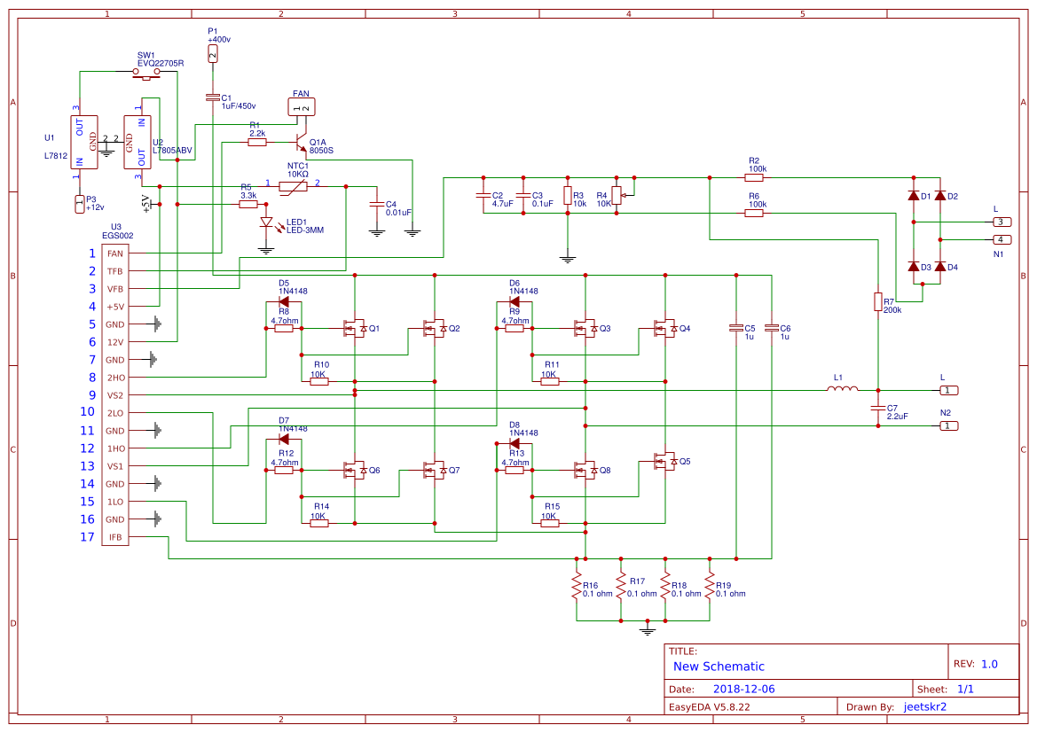
Where exactly did you connect the series bulb? If you connect it in series with the battery then I am afraid the inverter will not be able to operate a proper load at the output.
The bulb is supposed to be for checking short circuits only. The bulb must remain shut off if the inverter is working good. If the bulb lights up initially without any output load would indicate that there’s some fault in the inverter circuit.
I don’t think the egs002 might be fake or malfunctioning. It could be blowing due to some fault in the inverter design.
Did you provide the 5V and 15V correctly to the board? And also the ground connections?
Did you connect the mosfets as per the following diagram:
" rel="nofollow ugc">
Yea it’s a standard inverter board that has been working for some months exrxpt for emf feedback that causes damage to control board from grid when available. Thanks anyways for your support
You are welcome!
Hi
Thanks I will study d link. Want to ask. Whats the difference in efficiency in centre tap inverter model and H-bridge model.
Thank you
Sure, no problem! H bridge more efficient than center tap topology. The difference may be at least 10 to 20%
Hi swagtam
Love what you doing to the inverter users and fix community.
Am currently fixing a failed Chinese 6.5kva inverter which failed while charging it batteries from public grid. Have successfully fixed the inverter and it works fine. Unfortunately when I connected to public grid power power does not go into the pcb to start charging as before. No sign indicator that power is inside the inverter. But it bypass power to the house. When I open the inverter and check out the problem I can see that the relay responsible for taking Power into the pcb is not doing its work upon signals from the pcb board. Have checked tested the relay and it works fine also checked the low drop out relay and works fine with 3.3v output. Am confused which ic is responsible for signal to the relay to switch power into pcb. I changed the 2 lm324 ic and no change yet. What could be responsible for making the relay switch power into pcb. I don’t Wana manually bridge power into the board, I think its not proper. It’s logic should do it. Could it be the processor program is corrupt?
Thank you.
Thank you Daniel,
Your relay must be having a driver transistor. You can track the base of the transistor whether it is getting the required switching signal or not. So you can go on tracking the line which supplies signal to the base of the relay transistor and figure out where the signal is getting blocked or which IC or op amp is responsible for not supplying the switch ON voltage to the relay driver transistor.
Hi swagtam
Have traced the transistor responsible and its OK. But I also traced the relay to one of the 2 lm324 which is clearly responsible for switching the bypass/Inverter relay and had to change the two op amp ic but no difference only the first relay still works same the relay responsible for the battery charge and ac input still not responding and I don’t Wana do a direct link to the pcb.
What again do I do?
Thank you
Hi Daniel,
You must check whether the transistor base is getting the required switching signal or not from the respective source. If the transistor is OK, then it must respond to a switching voltage across its base and then switch ON the relay.
Hi swagtam
Guess you doing good. Please i need to know what could make a 2kva prag inverter working well for some months and all of a sudden begins to blow up light bulbs and damaging electronic. After checking the output voltage found out it was giving out 350v which way too high. This is abnormal. Never seen this happen before on any inverter. I suspect the feedback circuit but what could have damage it.
Need your assistance on a fix.
Thank you
Hi Daniel,
Yes, your assumption is absolutely correct. It seems the voltage feedback control has gone bad and that is why the automatic voltage control system is not working, causing the output voltage to rise to extreme levels.
You might have to investigate the components of the feedback network and try to troubleshoot the component which might be malfunctioning or blown…
Hi swagtam
Happy new year 2024. How you doing?
Am currently fixing a failed H-bridge inverter. One opposite side of the mosfet bridge burnt completely so I replace it with another number 1404 low and hi side mosfet against 7545 original there. The other half hi and low 7545 mosfet is still OK did not burn. Have fixed the drive that got damage and tested the inverter. The inverter is not working well to drive the transformer. I tested for out put on the H-bridge side it’s a output is fluctuating and not able to drive the transformer.
Could the mismatch of the mosfet be the cause since there 2 different number type mosfet on the board?
Thank you.
Hi Daniel,
Happy New year to you!
IRF1404PbF is rated at 40V, 202 Amp, RDS(on) = 4mΩ
IRFB7545PbF is rated at 60V, 95 Amps, RDS(on) 4.9mΩ
Both are N-channel.
If your inverter is rated to work below the maximum range of the above MOSFET specifications, then there is no harm in using any of the above MOSFETs. They can be perfectly compatible with each other.
If your inverter rating is below the above MOSFET specifications, and your MOSFETs are not duplicate or faulty, I cannot see any reason why the two variants cannot work together.
Thank you very much for your explanation. The inverter is a 24v system so I supposed the mosfet are compatible and fit with the system. However after fix the 2 drive chip it worked well initially and later started giving wrong output. I suspect the drive chip I bought from aliexpress could be faulty.
Let me change them.
Thank you so much.
Thanks for the feedback, yes that may be possible, I hope you are able to solve it soon.
Hi swagtam
If 10ohm bias resistor on mosfet is not good will it affect the inverter from switching and work properly? Because the inverter board is switching but no power out. What’s the real effect of 10ohm resistor on mosfet inverter board? Cos I found out the 10k to the gate is OK but both side were I changed the mosfet that damaged the 10ohm resistor is reading high value upto kohm n other side Meg ohm.
Is this responsible for the inverter not produce power and drive the transformer even when it switching fine by the drive chip?
Thank you.
Thanks
Hi Daniel,
Yes, that may be possible, if the gate resistor of the MOSFET is not good or very high value then the MOSFFET will not switch correctly and can become hot or malfunction.
Hello swagatam, please mistakenly fed the output of my inverter 220v while trying to add a change over relay. It blew the fuse of the voltage stabilizer( the inverter has a separate volt stabilizer connected to the transformer) I replaced the fuse,but connecting the inverter keeps sparking and burning off the negative battery wire with no output. Please what can do to rectify it? There are no burnt ICS or components,the mosfets are irf540n. It’s a squarewave inverter too.
Hi Ikenna, sorry I could not correctly understand your question. What did you exactly connect with the 220V output of inverter? was it a low voltage DC circuit?…in that case the ICs could have definitely blown internally, along with other semiconductors.
Sorry, what I meant was that i mistakenly fed 220v into the output section of the inverter. The inverter transformer is multi tapped and with a (fused) voltage stabilizer circuit. The fuse blew up, which I replaced. But now, whenever I turn on the inverter switch, the negative wire sparks and melts off the battery
OK it may be because the MOSFETs might have got burnt. When 220V was applied to the output of transformer, the other side of the trafo might have generated a 12V AC across the MOSFETs, burning them.
Replace the MOSFETs and check again with a fuse!
Alright, I will do as advised. Thanks a lot.
Welldone sir, pls, sir, i use inverter to my battery, and after charging i discover, that when i swtchon the inverter and load it, the mosfet will heat IMMEDIATELY and the tranformer is making noise, and the battery will bcome low. What is the solution sir.
Hello Ambrose, it means one of the MOSFETs is malfunctioning and creating a short circuit, or the oscillator output is not switching the MOSFETs correctly.
If the MOSFeTs are n channel, connect 1K resistor across their gate/source and remove the the input clock and switch ON the supply through a 2 amp fuse. If the fuse blows then one of the mosfets is faulty, if not then the mosfets are OK, the oscillator output has problems, check the oscillator output with a scope.
If rectifying the mosfets and the oscillator does not solve the issue then its the trafo that may be shorted somewhere.
Am having 24V DC (2 batteries) to 220 V AC Invertor, When Invertor is on (Mains power failed) Inverter trips every 5 mins, (it has auto cutoff facility for over load) , but in reality the load is maximum of 4 LED(18w EACH), 2 FAN (150 w EACH) , & it keeps on doing this for 6 to 8 Hrs. When I check Battery voltage during cut off & Cut on of Invertor, Batter voltage is 25 V, called the battery vendor & he says Battery is in excellent condition & asked to replace the Invertor Unit.
Would like to check if I can fix it or what can be done for repairing it or option is only to replace it. Am using this invertor from last 10 yrs & it was functioning well till 7 days back, but now having the problem for frequent tripping even if the load is very less.
It seems the overload sensor circuit is malfunctioning or may be it needs to be set up afresh. What is the overload threshold for the cut OFF? You are saying that the loads are 4 x 18 = 72 watts and 150 x 2 = 300W so in all it’s 372 watts that’s a lot of load. Did you check the response by reducing this load step by step.
Also please specify the max wattage of the inverter?
Hello.
Please, I installed an Eastman ESP 1050/12V inverter for a client. After a while, its showing FAULT SHORT-CIRCUIT.
I removed the solar panel cable and connected the inverter to the battery only, it still shows the same error. What could be the likely problem?
Thank you.
Hello,
If it’s happening without a load and with a good transformer then the internal sensing circuit may be malfunctioning due to some fault, which will need to e diagnosed stage wise
Bobby from Abuja,Nigeria.
please i have inverter prag brand of 2kva with 2 batteries 24 V, i bought the battery 3 weeks ago, when i connected them to my inverter, the indicator continue to beep and indicate high voltage from DC inputs and high load, it stops and worked normally after which i used it thrice, when i switched on after 3 days, there is no output voltage it is only beeping thinking the battery is low i tried to charge it, but there is no indication that is charging, when i connected these batteries to another inverter they worked perfectly
Hello Bobby, your inverter may be having multiple faults, which will need to be diagnosed physically, judging the fault without testing can be very difficult.
I HAVE A 2.4 MERCURY INVERTER JUST ONE MONTH OLD DE SREEN JUST WENT BLANK A TECH MAN SAID I SHOULD CHANGE THE COMPLETE PANEL I DO NOT KNOW WERE TO GO ABOUTE IT PLS
I guess the tech man is right, the whole LCD module might need to be replaced, since the problem may not be related to inverter, rather an individual fault.
hi sir
i have a exide pure sine wave850va home ups inverter
i bought a new amaron 150ahtall tubular battery recently 8 10 days ago
but today when power went off i got no currrent from battery and it was blackout
so when power came back i saw inverter was on bypass
so i put on mains and suddenly all lights were off inspite of primary power supply available
when i put on bypass the lights turned on
so whats the isssue in inverter
fuse is ok ichecked
Hi Manish, is the inverter working OK with the battery? Please check this by charging the battery fully first. If it is working OK, and also if the fuse is OK, then the problem naturally has to be in the switch.
Hello swagatam,
I have Su-Kam 600 shine wave inverter. one day it stopped working when I checked it was fuse fault. I have replaced the fuse. after that inverter is fine but when Main Power off all appliances like TV or PC restart or sometime inverter show overload. then I do on-off switch of inverter then it runs normally. what is the problem in Inverter or battery? though I check the battery it seems like Ok. I don’t want reboot my pc when power on and off. Please give advise. is that relay switch problem or something else?
Hello Kapil, if the inverter runs normally after sometime, then the battery may not be the problem, the problem could be somewhere in the inverter. Make sure the ON OFF switch is OK or if possible try replacing with the a higher rated one. Open the inverter and examine if anything is heating up or not. Even the heatsinks should not be too hot. Connect an ammeter in series with the battery positive and check the current consumption, and then multiply it with the battery voltage to get the approximate power consumed from the battery. Compare it with the total appliance power…check the difference.
Thank you swagatam for your reply. I will definitely check what you said.
You are welcome Kapil!
My pure sine wave inverter is not charging, which of the electronic components in the board should I replace
Hi Swagatam, I have a Lithon 2kva inverter it charges well with my generator but when I charge it with the main electrical source the mains light keeps going on and off and as a result it doesn’t charge the inverter well. Please what else can I do? Thanks.
Hi jesse, that looks strange, because generator electricity and mains electricity should be similar with their waveform, unless there’s a noticeable voltage difference.
You can check the voltage levels of the two sources, I think the mains voltage could be higher above normal which may be causing the inverter to trip due to high current into the battery
I have the Power Bright PW6000-12 and my unit started to produce 135.6v at 32 amps on all ports. What could be causing this problem? Could it be the feedback transformer? If it is indeed the transformer where can I purchase one? Where can I get the parts to fix it? Where can I take one of these to be repaired locally? What would I look for to find a place?
Yes, it appears the feedback could be leaking mains voltage into the DC side.
The transformer rating cannot be guessed randomly, you will have to check it practically with a meter to find its exact details.
I checked the voltage on the 6,000 watt msw 12v DC to AC 110-120 inverter the hardwire ports and all 15amp ports they all read 135.6v at 32 amps.
I was referring to the transformer specs, and whether it’s alright or not.
For confirming whether it’s from the feedback transformer or not, temporarily remove the feedback link and check again with a meter.
Hello, swagatam, you are really doing great job, helping a lot of people, it is appreciated.
I have a 3k inverex inverter by mistake we put all solar panel in series and it is now not showing anything related to Solar panels on LCD or charging on LCD, just battery connection or grid charging working fine.
It is not even showing up any error.
Please advise
Regards
Usman
Thank you Usman, I assume that the series voltage could have exceeded the tolerable limit of the LCD display and therefore some portion of the LCD might have burned. The charger stage may be still working fine because the charger controller could be having a voltage limiter which might have prevented the battery from getting damaged due to the high voltage.
I think you may have to open the LCD board and check for possible faults or may be replace the entire module. It could be a minor fault also, like a blown fuse or a burnt transistor.
Its honor swagatam, your swift reply highly appreciated, i ll change LCD module.
Now i have an other issue, by all means i tried to connect inverter with watchpower software via cable but no success, even changed cable but no success, can you pls advise ?
Thank you Usman, it’s my pleasure, however a software related problem can be very difficult to understand, because it could be due to some code mismatch or configuration mismatch. I can judge a hardware fault, but a software fault can be difficult to judge! Only a specialized personnel from the manufacture will be able to fix it.
My Name is David,pls I am confuse be after all effort to fix an inverter it still displays over load on the LCD how do I correct this?
It displays over load and some seconds it will reboot as if it will start the over load still comes up pls what could it be?
It may be either because your overload relay section is malfunctioning or there’s really a short circuit somewhere. You’ll have open the inverer and add a ammeter in sires wit the battery positive, if it shows a sudden high current then something may be shorting somewhere, otherwise you may have to diagnose the load correction relay stage for a possible fault
So what could possibly be the cos aside from the relay?
you’ll have to check with an ammeter as explained in the previous comment
Dear Sir,
I have come to customer site for online UPS(GPW100KVA).
But there is a problem showing on display.
“Internal Fault ”
“Inverter Fault ”
How to solve this problem?
Please guideline to me.
Best Regards
Nur Mohammad
Hi Nur, that can be difficult to judge, because the internal fault can be due to many reasons. How is the inveter responding when switched ON? Is this without load or with load…what is the status of the battery?
Sir.. I wasn’t around for some days and I left my inverter charging with the solar panels, when I got back I switched it on and there was a spark.I opened it and I found out that the fuse has been broken so I fuse it and it keeps breaking… Then when I check the battery’s voltage it was above 24v.. Upto 28-30v and after resolving the battery issue the fuse still keep breaking … Please what else can I check for
Hi John, how did you resolve the battery issue, meaning what was the issue with your battery?
Hello
I am looking for a complete training program to repair the freezer refrigerator onverter inverter.
For example, if the temperature is not displayed, what is the fault and how it is fixed, or if the engine did not work, where did it start, where to continue.
Thankful
If you have an electronic map from a range such as Samsung or LG, send me with descriptions like test points.
Thankful
my mail:rgolpayegani@yahoo.com
Hello, Sorry I do not have LG, or Samsung diagrams, I can only provide general tips applicable universally to all converter circuits.
I have a ups inverter 12V to 220V model 1200VA 220VAC, 50HZ 8A mAX 4.5A I use it on my plasma TV and I use batterie 12V 45AMP the light doesn’t last up to 20 minutes and trip off the transformer and the ic will heat very hot. Pls help
Please connect an ammeter in series with the battery positive and switch ON the inverter without an output load, if the ammeter shows high current would indicate a serious fault in the circuitry. Battery will discharge quickly if there’s some kind of short circuit due to faulty devices or may be a defective battery itself. If the heating IC is the oscillator IC then surely something may be malfunctioning in the circuit which will need to be diagnosed in a step by step manner
Hello Swagatam, thank you for offer me a BIC help to service 5000 KVA UPS, the problem was changeover rely I have got out form your answers thank you once again,
You are welcome Badereldin, I am glad it helped!
Good evening sir I have a 1450w (2.4) Mecer B-Bone inverter. I connected it to the wall but accidentallyforgot to remove the plug that power the unit and something burned instantly. It still works to charge 2x 12volt batties but as soon as I remove the plug it goes into fault with no output. I looked at all mosfets and found 6 that didnt work and replaced them. 1407 Still it gives this loooong continues beeeeeeep with no output. Could this be a transformer it has 2…. If it was I was thinking that the unit will switch off completely. It just doesn’t supply output
Hi David, could you please tell what this buzzer is supposed to indicate? Is it an overload condition? We can proceed accordingly once we know this.
Hello Swagatam
I have a 1500 watt ramsond invertor that I use with my off grid solar system. Suddenly It went dead. I checked the fuses (35Amp) and found two of them blown. I replaced them and when I connected the invertor back to the battery there was a spark and two more of the fuses blow. I replaced them and tried to connect it to the battery again. I connected the positive wire first and when I made contact with the negative I saw the sparks again i quickly move the negative wire. Why is it blowing the fuses when I try to connect it to the battery?
Hi David, whenever a fuse blows it’s a clear indication that there’s a short circuit somewhere! Looks like the mosfets or the power devices are blown in your inverter. You can trying verifying this by disconnecting the ground line from the mosfets. Keep a high watt DC bulb in series with the battery to safeguard the battery from an accidental short circuit while testing.
Sir,
I have 5kva/120DC online UPS/Inverter , Recently due to power failure batteries are fully discharged. and I charged the batteries with external power source and started the UPS. Now the problem is main power MCB is tripping some time when switch on the UPS, and DC power going down when I using the UPS. and I think battery is not charging. what should be the problem?
Anil, check the voltage of the battery while in the UPS mode and with a load on the UPS output, if you find the battery voltage dropping drastically then it would mean your battery is not charged. You can do this externally also. Connect a calculated heavy DC load across the battery terminals and check the voltage if it quickly drops then your battery is not charged properly or is damaged.
Another way is connect an ammeter in series with the battery and the UPS, and then check the ammeter reading. If its low and with battery voltage dropping then the problem is with the battery…If not then the problem could be with the UPS circuit or the changeover relay circuit.
Battery will not charge if the battery fails to retain the charge due to internal damage…
Thank you Sir for your fast response,
Sir, my UPS ( its not a digital inverter) is 10 years old and Batteries are two years old. The manufacturer discontinued the model and not giving service. The UPS is working fine in battery mode, but I can’t put on main power because it is tripping within one minute. DC input is showing 130V in UPS panel. all battery indicator showing green lights. no charging sound is coming from UPS (earlier it was there, when main power goes and come the charging sound can hear clearly. now its stopped. Sir if you getting any idea from my reply please help me.
thank you once again
Hello Anil, so you mean to say the problem is not with the battery, it’s the changeover relay circuit that is showing problems? In that case it will require a practical testing without which understanding the fault can be difficult.
Is it responding the same way without batteries? meaning without batteries are you able to operate it in the AC mains mode?
Yes Sir. I checked UPS on main line without battery. Main line MCB is tripping within no time. What should be the problem. Is the problem with changeover relay switch or circuit board
Yes, the changeover stage could be malfunctioning, it may be having an opamp sensor which is wrongly detecting a mains failure like situation due to some problem in the circuit.
You will have to identify the relay stage and then troubleshot it or may be replace it to correct the issue!
Thank you Sir for your valuable advise.
In this world it’s very difficult to find a person like you. If I approach a service person, may be never explain like you.
I salute you for your knowledge and your dedication. Keep going.
May God bless you.
Once again Thank you very much.
It’s my pleasure Anil, let me know you if you further problems.
Sir,
Of course, I will let you know what is the progress and what was the problem.
Thank you
I have a 650W sinewave inverter 12V to 220AC 60 Hz with trolley.when i bought it second hand it was working well except when I put a plasma TV using off grid ,the TV would switch off on its own after about ten minutes, so I stopped using the TV and use it only for lights.Now when I try to put it On its just taking seconds and becomes off…tried to charge the battery but still the same thing…and its showing just zero on the display and its coming with some noise..and when I put ON grid power direct to it its not coming On.What could be the problem
The important thing would be to check whether the battery voltage is reaching the inverter or not. You will have to open and trace the wires from the battery and check the changeover relays in between and how they are operating. Or you can try bypassing the changeover section to directly connect the battery with the inverter.
Hi. Swagatan , My friend brought Fortune DSP sine wave Home UPS FR1000 to check why the inputs and outputs of the unit were not being read on the LCD Display. When you connect it to the12v battery ,it reads: Enter Se and starts to ran through the settings without figures. eg AC IN = ,AC OUT = ,Hz IN and Hz OUT = ,DC IN and DC OUT = , etc. P/se help. main components are : ICs PIC16F676 , PIC30F2010 , 6N137 , LM7805 ,LM393N ,MOSFET90N55F4 ,LCD Display , Power switch , 3 x indicators, at the back : CPU and HYBRID sw, INV and UPS sw ,AC outlet ,Battery terminal ,Solar terminal ,etc.
Hi N Bwale, I can only provide general tips for general faults, it can be difficult to judge a brand specific fault without checking it practically.
I change the power card of an 3kva nexus Inverter and yet when Ac is applied it will display mcb protection while the output will go off pls help me on this.
I have a prag inverter 2kva /24 with two 200AH batteries. It suddenly started making vibrating sound with a hurriedly beep when on Battery Mode and after a while it drops the battery bar from 4 to 1 bar with “UNUSUAL” display on its LCD and later switched off.
It doesn’t make same vibrating sound when on Mains and it shows charging.
What could be cause the vibrating sound and dropping of battery capacity bar on Battery Mode? Please help because I can’t use it now. Thank you.
A vibrating sound from an Inverter is definitely an indication of a short circuit somewhere in the main board, either due to to faulty mosfets or due to a burnt transformer. During AC operation the battery is disconnected from the inverter and therefore the short circuit condition is removed. You must consult an expert to diagnose the situation deeper.
Sir i have luminous inverter ,when the mains is on /off the output socket polari ty is changed
Means if mains is on tester indicate live current in Left output socket while on main off or loading in inverter tester indicate right socket live wire
Pls help
Hi Ashish,
Just change the polarity of the mains plug wires, it will solve the problem
Hi there, great to have someone with so much knowledge answering questions.
Mine is fairly simple. I was hooking my inverter up to an automatic transfer switch and incorrectly read the diagram and had 120V pumped in the output of my inverter. There were no sounds or smoke…but I am not getting output even though it looks like the inverter is on and working. I didn’t see any blown caps or visual damage of any kind. My question is do you know what would be the first component to go in a situation like this? where the damage would be?
Thanks for your time.
Hi, By pumping mains at the output of the inverter you might have subjected a high AC to the mosfets which might have blown due to the reverse current. Although reverse protection diodes are normally present across the drain source of mosfets still the situation could be unpredictable in such circumstances.
Firstly you can confirm the situation by checking the output directly across the transformer output wires, if you find no voltage then certainly the mosfets are blown you may have to change them all.
Sir, I have Luminous 800VA inverter with 150AH battery. Inverter is 6 yrs old. Suddenly I have found that all the “Overload”, “Noload”, “Smartcharge” indicator is glowing at the same time. Along with it is not waking up automatically when there is a loadsheding. I have contacted to Luminous Service Engineer. He suggest me to change PCB Board with cost 1250/-. But he has only 575VA and 875VA board instead of 800VA. But I have asked him to replace with only 800VA board. Now my Questions are…
1) Is my problem due to Faulty PCB board…????, But there is no burn issue and other major malfunction and giving backup voltage properly(manually).
2) If I change the board with 575VA or 875VA instead of 800VA (which is already presenet in my old Inverter), will there be any problem…??? Because he is taking long time to order 800VA PCB from Company.
Your urgent reply is highly solicited, please give me suggestion.
Dibyendu, the whole board may not be faulty, but a section of it may have a fault due a faulty part. A part such as an IC can go faulty even without burning, may be due to a sudden spike in voltage or due to another faulty part associated with it.
you can replace your 800va board with 875VA board but not with 575VA board, however the company engineer will know better about the internal specifications, so you can consult him about this thoroughly. If he confirms it then you can go ahead with the 875VA board.
Hi,sir
I have a 1500w modified sine wave inverter (12V DC to 220V AC)(50HZ) .it’s got overload and stopped working i replaced the faulty mosfet .Unfortunately even though the device has been working,it has problem when i tested the output by millimeter it is around 60 volts AC (50HZ) instead of 220V AC how to fix it .
The battery is o.k.
Hi Hizam, you can connect small filaments bulbs in series with the mosfet drains and check whether all the bulbs are oscillating with identical brightness or not. This will confirm whether all the mosfets are conducting or not uniformly. Because voltage at the output might malfunction mostly if the transformer is partially burnt or the mosfets are not operating uniformly.
Hello,
My name is Bashir and I really have a problem with my Luminous Solar NXG 1500 1.5kva inverter with two 165ahms batteries. I mistakenly connected the positive wire to the batteries with negatives, it sparks and I immediately corrected the connections. Upon turning it on, the batteries refused to charged. Only the “On Main” indicator is on, while the “Main Charge” is not charging.
Please, kindly tell me what to do as I live in a place where repairers are hard to get. Thanks
Hello, it seems the internal charger controller has been damaged by the reverse battery connection, it’s very strange how come such reputed system did not include a reverse battery protection? But anyway you may have to diagnose the charger section to identify the fault…
Hello sir? I am very grateful with your work and I just imagine the traffic of questions you answer in a single post!!! Only because you are doing whole heartedly……
Sir , I have a broken down inverter 3kva, MKS Axpert make, it uses a dc to dc booster I don’t know maybe it’s called transformerless inverter.
It is with error code 05 ( output short cir cuited) I took it to a an inverter tech but tried and tried now he have up. He is the only hope in my area.
I even checked the inverter my self and I cant figure how the oscillation stage for the h_bridge is configured becos there are severeal ics thre that include :
1. lm339
4 .tl074i
2. 14081bg
1. 14070bg
1. Unmarked control ic.
I removed pin 10 from ground to prevent auto shut down and dc to dc is working with output350-400 vdc.
My question is ,can I get rid of original oscillatory circuit and construct a seperate one and use bc547 and bc 577 on driver stage.
If possible suggest ideas and schematics,I also want to return short circuit protection, overvoltage,and output voltage regulation.
Hello Thatcher, you can replace the original oscillator with your own but you can do this only if you are able to figure out all the details about the functioning of the various stages and if you are confident about the various connections that would associate with the oscillator.
sorry I won’t be able to troubleshoot the design without seeing the schematic.
Hello Sir, please I have an issue with a kmb 1000W inverter. I forgot to switch of my inverter as it was on when supply from public power supply feed into the and thus causing it’s mosfets (IRF1404 and IRF840) to burn. The inverter then show fault light. Now I’ve changed the mosfets but the light is still on and no AC output from the inverter. However it still charges my battery. Please what next do I do.
Hello OLudare, you may begin by removing all the mosfets responsible for driving the transformer, and then check the gate source of the mosfets whether this source is correctly producing the frequency from the oscillator or not.
If yes that would mean your oscillator stage is OK and the mosfets would oscillate normally allowing the inverter to work normally, that would imply your fault light stage has some probelms, you can diagnose this by checking the signal source which may be causing it to incorrectly trigger, or you may temporarily isolate this stage entirely and then check whether the inverter now starts working or not….
I have a 2kva Mercury inverter but if I power it the inverter will be showing fault light and it will not powered
connect an ammeter in series with the battery positive, and verify if really there’s a short circuit happening somewhere or not…if not then it’s the LED indicator sage which may be malfunctioning.
I have 2000watt inverter. After Thunder strikes it can no longer supply light again, but the green and red light keep blinking. After like some seconds the inverter will be hitting very serious!!
Pls,, sir can you help me?
If its hit by lightening then I am afraid the damage could be significant, it would be difficult to troubleshoot it without a practical examination..
Dear Swagatham,
I have Sukam sturdy sinewave inverter 650VA. I recently started facing an issue with it. When i give the battery connection the Mosfet starts burning? I have replaced the Mosfets with removing the connectivity of the Inverter transformer. But still the same problem persists. I am not sure what to do with this issue.
Need your kind help.
Thanks
Dear Shyam, if the mosfets are burning even after replacing them then possibly the driver circuit is burnt and is not oscillating.
Before connecting the mosfets check whether the gates of the mosfest are being supplied with the required oscillations or from the concerned IC circuit
Microtek 900EB INVERTER IS NOT CHARGING
@Swagatam, my inverter was unknowingly reversed the input terminals, +ve from the battery connected to -ve of the inverter and vice versa. Leading to death of the inverter. Is this repairable?
help to to my gmail:
jkangogo64@gmail.com
Hi Julius, it is definitely repairable, however it could be a lot of hard work to test and replace the burnt parts, which could include ICs, mosfets and other semiconductors.
Hello Sir,
I have a powerlink inverter of power transistors type it was working well from the last 16 years,but now its giving buzzing sound so many time in a day continuesly at that time no lights or fans works, if any time in a day it not buzzing all light and fan will work .Pls suggest
Anil
Hi Anil,
The buzzing sound is from transformer or relay?? Please connect a heavy duty DC bulb in series with the battery positive to check whether the circuit is creating a short circuit or not? If the lamp illuminates without any load at the inverter then the circuit could be having a short circuit somewhere!
I have an invertor charging not stop please tell me where I can find the problem and how to repair
The IC or the transistor controlling the auto cut off relay may be malfunctioning, check the IC or the transistor associated with this relay.
Hello sir,
i am ausing a su-Kam 600VA sine wave inverter. at the of house shifting accidently connected my battery in reverse polarity ,therafetr i have changed the polarity but it is not working and seems it has got damaged.visual inspection shows no sign of damage. can it it be repaired ? if yes then can you plz tell me the important steps to be taken……i read similar amswers but worried whether su kam might be having diffrent circuitry……plz help
Hello Subhash, that is very strange, how can a reputed inverter brand not include a reverse battery protection??….if that’s true in that case you might have burned a few crucial stages of the inverter circuit such as ICs and fets, which cannot be predicted without actually checking it….even a fuse couldn’t have prevented this from happening…I would recommend calling somebody from the company and explain him about this issue and the possible remedies.
I have Sukam 650 inverter from 2 year working ok but now I change my home and I connected inverter but there is a problem that when main supply on fan speed is ok but when supply off or gone inverter output is low and also fan speed very slow while my battery is new purchase on august 20 ,2017 what is the solution of my problem
This can happen only because of one reason, battery not charged optimally, check the inverter output with a meter and with a load connected, if it shows a drop in voltage would mean the battery is not charged properly, and will need to be charged for some specified period of time.
Hi! Would you mind if I share your blog with my myspace group?
There’s a lot of folks that I think would really appreciate your content.
Please let me know. Cheers
I am using EXIDE 1050VA ,12V inverter ,when there is any short circuit I have to on/off inverter even if the short circuit is removed,can this problem be eliminated as if there is any fault in inverter supply ,inverter should turn off,but if the fault is removed it should turn on automatically, please help…
It seems the inverter is designed by default to latch up during a short circuit, and I think it is a recommended feature, and should not be changed. however it can be modified by opening the relevant stage and by checking and removing the part responsible for this action.
Hello,
I have a chicago electric 750W power inverter and tge fuses are good, however, there is a diode ( I think) yhat has burnt up right by the dual red wires running to the hookup location. Can’t make out the the color rings in it at all. Can you help me?
Hello, please specify the exact location of the diode, from where are the mentioned wires originating, and at what place are these hooked up?
Greetings to you sir, my index inverter, 48v 5kva was affected by lightning and now it is displaying overload fault even when no load is attached. What should I do sir. Thanks.
Hello justin, that can be difficult to troubleshoot without an actual check up, because the lightening might up burnt some sections of the inverter which will need to diagnosed thoroughly for identifying the fault.
you can do one thing, open the inverer and check the voltage directly across the transformers output wires, if it shows proper voltage and is able to power a specified load, then we can assume the fault to be in the overload indicator section, which could be then separately investigated
Thanks for your response. Done the check as directed, it can power a load. Tested the sensing transformer 400/0-23V, its output voltage is 11.6V. All other components like the diodes and resistors in the sensing area are ok. Thanks
OK great in that case you can isolate the sensing section and verify is separately….
Thanks. I will work on that immediately.
There is another genus 3.5kva 48v inverter. When switch on, it beeps very high, no display on LCD screen and it does not turn on.
OK will do, you can perhaps investigate it in a similar fashion…
i have a 600w inverter when i switch it on it states overloading how to fix it
I have 5kva/96DC Inverter , recently replace new batteries 8 pcs x 200Ah, after connecting all batteries I started the inverter and its tripping with alarm on and panel reads 2 messages ''MAIN FAIL INVERTER ON'' and ''PROTECTION'' SHORT CKT/OVERLOAD after replacing batteries it does not charge and Batteries are not fully charged , Does it require fully charged batteries before installation of new batteries?
What could be the issue of getting this messages and inverter triping
It looks like some kind of internal technical fault…it's not due to low battery…otherwise you would have got a LOW BATT indication.
still, you can try charging the batts externally and try again to see the effect.
It will need to be examined by opening the inverter, It cannot be judged by assumptions
Hi Sir, i have inverex inverter and not taking load on battery while AC power is off.
problem started after phase and neutral swapped at AC input to inverter mistakenly.
swap resolved but still the problem is there
only one circuit breaker present (outside boday) for input circuit and that is fine as its function well on AC input means battery charged properly and load also taken well but when AC supply get off, all load gets zero while battery showing 4 (max) cells charged.
Hi Support ALU, the input phase/neutral can be connected anyway round, that cannot cause any problems to an inverter or AC operated unit. You seem to be misjudging the fault…the fault could be due to some other reason not because of phase/neutral swapping….you will have to diagnose the fault by inspecting the various stages using a DMM.
HI All,
i have an inverex inverter which is now not giving battery output to load after phase and neutral swapped of AC supply by mistakenly.
what should be the probable cause.
shakeel
Hie bros
Am new here and also newbie to electronics and I want to explore, learn as and become an expect. I have been following your posts for a while.
Am desperately in need of your help.
I have a 3kva 2,4kw mks apex DC to Ac pure Sinewave inverter off grid. It was working fine all along with load of about 170watts during day and about 300watts at night. Sometime last year during the day, I heard popping sound in the inverter and suddenly a buzzer and an error code 05 ( output short circuited). I opened it and found from the output array, one side one mosfet had blown casing and the other had one leg blown,the other two were fine. I checked for any other components failure but could not find any and I replaced with new ones and worked again finely for about 4 months and repeated the same. This time it blew two resistors near the mosfets ie 100ohm and 4.7ohm, I replaced all but when I turn it on the error code 05 is shown and no AC output.
I tried checking every component I could except for the ICs becoz I don't know how to diagnose them. Where could be the problem? NB the big caps on the high voltage area are charging when I turn it on.
Please help.
Hi Francis bro, you will have to identify the exact position of these resistors….If it's one of the gate resistors then the problem could be more serious, since that would mean the driver IC has been fried this time….because normally the gate resistor is isolated with a high impedance, but if it is blown then the associated IC might be also blown.
But the main thing to consider is why these short circuit issues are happening repeatedly? and isn't there any fuses connected with the battery or the trafo output…?
you must ask the manufacturer why it is not automatic…
Sorry, I do not have much information about the features of these equipment because I do not deal with them very often…so I won't be able to help with this…
My invert er was working perfectly all of a sudden it stop bring output and leakage was observed on the neutral point but when inverter is disconnected the leakage will disappear. what us the cause?
sorry, this problem cannot be judged without practically checking it….
In my home inverter when power goes it is not start automatically from battery .But if I change the switch position regulated mode /Deregulated mode (any change ) then all appaliencence run from battery .I need to change every time if power go.
it seems your changeover relay section has some fault…you must open the inverter and check the section which is responsible for executing the automatic changeover and check why it may not be responding to the power failure
Dear sir, when I switch the main supply off. And I checked the switches which are on inverter then it shows 330 volts. Isn't it too much for my appliances.. Also when I put tester in these switches the light glows in one of the hole.but when I turn switch on. Light glows in both live and neutral. Is there any problem with my inverter
Varun, it seems like your inverter does not have a voltage regulator, and therefore 330V could be dangerous for smaller appliances. to correct this you can use a lower voltage battery.
mostly inverter transformer secondary work in a push pull manner which causes their output wires to switch between LIVE and neutral alternately and therefore will show live at both ends…it is normal and nothing to worry about
Shivam Singh I have an arise inverter . It usually sparks at input plug when I consulted electrician about it he said sine box is fused . I want to know what is the reason of its fuse and how it can get repaired.
sorry I did not understand what is sine box?
thank you
I don't know well about schematic form but I tried to clarify everything in the pic.
SMPS will get power from (AC main) and the (L) wire of the smps will be connected to the relay and (N + E) wires will be connected to 3 pin Socket.
Relays are connected in parallel and getting power from smps, the inverter input wires will be connected to 3 pin socket of my circuit
https://drive.google.com/open?id=0B_2QrDIghjN1MzBOYVlYY2hBbTQ
actually without proper symbols, I am having difficulty in simulating the design the design in my mind,
Ok I'll check this new diagram and let you know you soon…
I have checked the diagram, it looks OK to me….the second battery will start charging when the first battery is full.
and the 3 pin socked will get the inverter mains whenever Grid mains fails….but the battery will be always connected with the inverter which can cause slight consumption all the time….
Thank you, I'll try to build the circuit
I read your topic about Solar Panel/Battery/Mains Changeover Relay Circuit and I built one to suit my requirements my goal is thet, when grid is there charging is done thru inverter and the solar charge controller charging the second battery but in the absence of grid the solar charge controller charging the battery which connected to the inverter.
could you see the following diagram please I want to be sure if it's safe to use this circuit.
https://drive.google.com/open?id=0B_2QrDIghjN1Tmp5VGdVNGhUeEk
I am having difficulty in interpreting the connections because it's in a block diagram form
I would be able to check it better if it's in a schematic form
https://drive.google.com/open?id=0B_2QrDIghjN1MTcxRkxmQ3BiNk0
How much watt this inverter can hold?
There is no battery low voltage warning or float stage like sukam, can you help me in that please?
how to reduce the transformer humming sound, it's too noisy
sorry I cannot judge the specifications by seeing the image only.
I have published many good battery charger circuits which you build and combine it with this power supply…one of them is this
https://www.homemade-circuits.com/2016/05/opamp-low-high-battery-charger.html
You were correct, the problem was with the relay pins, When I told you that the inverter wasn't working I was wrong for running the inverter battery should be attached and I think it's normal for the transformer to produce humming sound because it is a square wave inverter.
I want your suggestions for the followings:
1) Is it safe to run 32 INCH LED TV?
2) I installed 8A fuse, Which fuse will be suitable because it's not written on the case of inverter?
3) Is it normal for ceramic resistor getting hot?
Thank you so much sir
OK, no problem!
1) All LED/LCD TVs have an in built SMPS circuit which will confortably convert any form of AC to DC for the operation, it a square wave can eb used without issues.
2) for the TV you can use a 2 amp fuse, will be enough.
3) if it's a high watt resistor then little warming can be OK, otherwise it can be a problem…then it must be checked.
https://drive.google.com/open?id=0B_2QrDIghjN1ajhHM1NXRmtHWkE
https://drive.google.com/open?id=0B_2QrDIghjN1THhod1hQVXUxMHc
https://drive.google.com/open?id=0B_2QrDIghjN1dzk1dmttUmxobzQ
https://drive.google.com/open?id=0B_2QrDIghjN1bVJhV2xQdl9OODA
https://drive.google.com/open?id=0B_2QrDIghjN1S2NQaGEydUQyV1U
https://drive.google.com/open?id=0B_2QrDIghjN1MmNBTFg4V0Q1anc
Thanks Ahmed, I have checked the images and it seems you have already figured out the pinouts of the relay correctly and have wired it correctly….but it's strange how you are getting 48V instead of 220V.
However I am having difficulty in understanding how the relay is switching the battery charging voltage which is supposed to be DC and how come it is also switching the 220V AC??…if possible please draw a rough schematic and show it to me so that I can understand what voltages the relay is connecting to and where exactly these voltages are going…??
hello SIR
without changing the relay when I put the switch on charging mode output
wasn't there, but when I soldered the new relay in the place of the original
one inverter didn't work at all, I searched the net to know how to identify
relay pins and I figured out that the ON and NC are in opposite direction so
I soldered the relay as shown in the following pic:
https://mega.nz/#!wEAFSLAJ!hy0iDcSWAuZXdqOYmEj4v90XiVMn_o3Amxkm3lh6QBg
and when I put the switch on charging mode output was there but in inverter
mode I got low voltage around 48V instead of 220V.
please download the following pics may be you'll find the problem because
there is another relay and physically is good but I haven't test it
https://mega.nz/#!QcZWhAbZ!A0gvwNFx3e_gDiUKOo4qz-eqANfgbaqnKdP8MkrghYw
https://mega.nz/#!5VIlnaSR!MDXLriAU6kUqGdxbCO7o_obfenSFPjCOADVdcYePgaI
https://mega.nz/#!9U4SRSyK!YZIgaSCleGPbxcS1GeiN6bhdYZxiyvfCOfNtdwIdN-c
https://mega.nz/#!QV4S2aab!8z7R_LL1jHEWfLp4doXpjvzb8Gl0R2xTc5BifJIj-kE
https://mega.nz/#!RJACUIpK!ikEvHfv9qV1KSbQ5oLugydJrML6bhwbvxb1KNobPNw8
Hello Ahmed, please upload the images on a site where I can see them directly, without downloading
or you can share it through Google drive.
N/C of a damaged relay has a different position than chinese relay, when I soldered the relay I changed the wires too, but I have a problem, the transformer produced noises and I used multiple fuses but the result was the same, when I connected the pulb, it didn't light properly (produces very weak light then it was damaged). there is a ceramic resistor of 30w 0.1 ohm conneted to the middle pin of SPDT switch and fuse, do you think the problem is with the resistor because when I changed that resistor with wire I got same result too
You will have to identify the N/C, N/O and the pole of the relay for making connections correctly.
the resistor may not be affecting the response because 0.1 is too low, but it's better to remove it anyway.
If the transformer is producing noise, that indicates a short circuit being produced by the relay operation, so i would suggest you to first confirm the contact details using a multimeter before implementing it practically
Hello Mr. Swagatam
My friend gave a manual AC-DC inverter battery charger, it was not working because of a damaged 5 pins mini relay, the specs of the relay is as follows:
10A 120VAC
10A 24VDC
COIL 6VDC
I change it with the following one:
10A 125VAC
10A 28VDC
COIL 6 VDC
the problem is that inverter mode not working, but when grid is on and put the switch on charging mode I get output
Hello Ahmed, Your relay replacement is correct, however you might have connected the relay contacts incorrectly and not as per the original specifications, so please check the connections again and make sure the relevant relay terminals are connected exactly as per the original format.
for more relevant info you can check out the following article:
https://www.homemade-circuits.com/2012/01/how-to-understand-and-use-relay-in.html
Hi Swagatam,
I have one Microtek SEBZ & other Bajaj make UPS both for 12V single battery DC to 230V AC.
I have added them with battery bank of 24V, such a manner that each battery is fed to each inverter but there is changeover switch which can alternate their AC output manually. They can never put online simultaneously.Trouble starts with Bajaj inverter when on load it reverses the output live terminal.
That means when I load it checking the load socket of 15A plug it shows power to the neutral& vice varsa. The other Microtek is working fine. Worthy to mention I have single live wire connection for inverter to load & Neutral & earth being used from electricity mains. Inverters so connected with single battery because I have my 300Wp solar panel of 36Vmp so I have connected them in 24V from 12V & getting better result.
Hi Asimkumar, I could not understand one aspect, if you are using the mains Neutral for the load, does that mean that you have connected only one wire from the respective inverter and the UPS and left their other wires unconnected?
Please clarify this point, once I understand this I will try to sort out the problem for you.
I have measured the battery an transformer just to find that the output is not there. Mainly because the input is all positively charged with no negative present. It has two Daughter cards one has a pwm generator with oscillator out. Is that what is driving the mosfets? I assume the fets are Beiing pushed high and low when it's working correctly it is a pure sine so I have 8 fets at the two transformers and 4 at the output stage which appears dead. It also uses 3 opto couplers to switch the high side to some extent. Any ideas? I need a schematic for this. It is a power tech-on ps1002 1000w pure sine inverter
Sent from my iPhone
On Mar 27, 2017, at 4:03 AM, Swagatam Majumdar wrote:
Swagatam Majumdar has left a new comment on the post "How an Inverter Functions, How to Repair Inverters…":
Hi, the LED indication cannot be considered as the final judge of the situation…the LED could be ON due to some other issue. the main diagnosing must be conducted across the transformer leads and the battery leads, and the oscillator section….if the oscillator sends the signal to the mosfets, and if the mosfet drives the battery voltage to the transformer then an output will be available.
Post a comment.
Unsubscribe to comments on this post.
Posted by Swagatam Majumdar to Electronic Circuit Projects at March 27, 2017 at 3:33 PM
The measuring will need to be done by connecting an ammeter in series with the battery positive lead..it must indicate the correct specified amount current, otherwise it would indicate a faulty mosfet or a faulty oscillator stage or both together.
Sorry I do not have a schematic for this…basically all inverters work with an identical principle so fault finding shouldn't be too difficult, if it's done by isolating the stages and checking them step wise
Hi, I have a power Tech-on 1000w pure sine inverter. I use it as a back up power source normally connected to batteries under charge with regulated solar panels. After 13 months, 1 month past warranty period, it no longer produced AC output but green indicator light comes on as usual with no fault led coming on. My past experience with inverters was usually replacing the power mosfets. However I did that and also main transistors on both sides of power transformers (2) after trying to diagnose, I lost the steady green led. Have you heard of this issue? I cant find a schematic and the manufacturer does not offer any repair service. I would really like to know if this is a fixable issue. Any help appreciated
Hi, the LED indication cannot be considered as the final judge of the situation…the LED could be ON due to some other issue. the main diagnosing must be conducted across the transformer leads and the battery leads, and the oscillator section….if the oscillator sends the signal to the mosfets, and if the mosfet drives the battery voltage to the transformer then an output will be available.
Hi Swagatham,
I have a 5000VA SINERGY DSP sine wave inverter. I have owned this for over a year. Recently, I have been getting the *protection* short circuit indication with a loud continuous tone. This happens about 15 minutes after the mains loses power. I have to manually turn the inverter switch off and on before it operates again but only lasts for about 10 to 15 minutes before the short circuit display comes on again. When the mains is powered it works normal. Any idea what to check please?
Hi Oloruntoba, It can be difficult to identify the fault without checking it practically, it seems to be some internal malfunctioning of the relay changeover circuit stage. you will have to consult the company's service engineer for troubleshooting
Hi
I have a 5kv MPP Solar Invertor.My problem is its failing to charge the batteries when the panels are connected to the invertor but when I connect the panels directly to the batteries they are being charged.I would then reconnect the wires to the invertor and I can have the power for the house.No fault is showing on the LCD beside the non flashing of the charging light.
Thank you
I bought 2 APC smart UPS 3kv and they developed a fault suddenly not too long from when i bought them. The first one will work for 2hrs and after then it will start blinking all the led display light that it has and the output voltage will cease from supplying. The second UPS of the same model just stopped charging suddenly and whenever its is plugged to AC, it will also be blinking all its led light and start making a disturbing sounds. Pls what do u think i can do to that?
It does not seem to be a general kind of fault rather a model specific fault, will be difficult to diagnose without a practical test….for the first unit you can try testing it with small loads and see whether the problems repeats or not, if not then the problem could be due to overheating of the devices inside.
Thank you Swagatham,
I can't find my post, so I hope this reply gets attached to it.
So, you are saying to add an external relay changeover system with a battery charger?
Is this in lieu of the inverter? Or just for the time of the changeover?
Are you saying that my Su-Kam Inverter cannot be fixed?
Are you also saying that I should NOT purchase a new inverter?
As you can tell, I am an electronics moron.
Do you think the servicemen from Exide will be able to get this together for me?
Will this all cost more than a new Inverter?
Are you saying that a new inverter will encounter the same problem?
The exide servicemen came again tonight, because whole day the Inverter was on and I just shut the whole thing off. I called them and they WANT to get it right. But, even with the Electric switch on EB (not battery) and the button of the inverter OFF, I found the inverter charging with mains ON when they came at 6pm. This was ONLY in the evening; the whole day was only inverter and I shut it all off. How can it charge when it is all off?
The whole thing is weird.
Please, a little more info would be helpful for me.
Thank you again.
You are welcome Chandi Devi, you may have to click the "load more" button to see the hidden comments, it's hidden under this button.
I suggested the idea of an external changeover just to make the operations independent of the inverter unit since the chaneover/charging operations are crucial to the inverter and the battery.
You can definitely get the inverter repaired if you wish so, that's never an issue.
If the whole thing is concealed and wired then it could be difficult to use external circuits with it, rather it would be better to get it completely examined and corrected by the repair personnel.
Alternatively you can buy a battery charger and an inverter separately and then wire them externally as per my circuit suggestions so that in future such complications never arise or is easily tackled.
Dear Swagatam,
I have a SU-Kam Falcon 800 sine wave inverter. It is around 6 years old. I bought it with a SU-Kam Big 180ah tubular battery. The battery went out a few days ago, at least it tested no voltage, and I bought an Exide 150ah Inva Tubular. The inverter was checked and found to be fine! So we hooked up the new battery!
Where I live we have both 2 phase and 3 phase current going on at different times of the day, as this is village and small farm agri area also, so we have power cuts when the phasing goes on.
At the start, the battery was fine, but after the first power cut, the inverter stayed on instead of switching back to "mains and charging' cycle,which means the battery was still supplying the current while the current was now back. I had this problem with the SU-Kam for the last 2 years, so the SU-Kam serviceman told me to purchase a 1kv stabilizer so stabilize the incoming current so the inverter would be able to switch into the mains and charging phase, so I did. However, I found there were times when the inverter still stayed on after the current returned!
Yesterday, all day the inverter stayed on, even though there was current!! I shut off the inverter and switched the wall switch to main current!
I already called the battery company, who came out on the first day this happened, and they said it was low current from the EB itself!!! They suggested I use the stabilizer! But, I am wondering if the inverter has a problem, because it did not switch to mains and charging after futs, but stayed on inverter the full day! I kept shutting it off, because I didn't want to overuse the battery or kill it's load!
I am confused at what is the problem! I am thinking of seeing if I can find a good condition used inverter to check if it is the fault of the inverter or WHAT is the problem? Now, I have shut the whole thing off!!! Can you help?
Thank you, Chandi Devi
Dear Chandi Devi,
A stabilizer is irrelevant for the issue because a changeover circuit is the simple circuit which can be operated with a couple of good quality relays…and these relays can be controlled with a 12V SMPS or a simple 12V regulated transformer power supply.
the problem ie definitely with the inverter and the technician seems to be clueless regarding this simple issue.
you can probably solve the issue using an external relay changeover system with a battery charger which cab be independent of the inverter and yet provide you with the required automatic mains to battery changeovers and also charge your battery while mains is present
Hi..sir…what is the voltage value output at amplifier
Happy new year, pls i saw my sukam 1400 on smoke, so i put it off, then on cooling down, i try to putit on, but its not working, no ligths at the dash board. Pls what can i do to fix it. and possibly what is the cause of the smoke and how to avoide future accurance
Happy new year,
sorry that could be difficult to judge without a practical testing because a smoke could be caused due to many different reasons. The result of this could be serious damage or minor, can't pinpoint without checking
you can check the fuse or the parts around the fuse…also the mosfets could have gone faulty probably
Hello Swagatham
i have a invertor of Luminus Tez and we see that before some time battery is not charging and Charging Zip is blinking continuously , we clean the battery terminal and even not charge battery…plz help
Hello Satish, please check the current by inserting an ammeter in series with the positive line connected with the battery….you can also confirm the voltage across the charging outputs using a voltmeter without battery connected.
if both these or one of these reading produces a zero result or lower than expected, in that case your charger circuit could be internally malfunctioning…
Hello Swagatham,
Today I bought an IPS Exide 1050va, when I connect battery with inverter and turned switch on, it gives no backup. But when I put the power plug into the socket, it works normal though mains have no electricity!! So, what's the heck on it?
Hello Ashik, after plunging in and starting the inverter, if you remove the plug, dies the inverter continue to run? If not then the inverter circuit functionality could be associated with the mains neutral wire and that's the only way it may have be designed to operate.
So i have a friend who connected the cables backwards and now the inverter doesnt work. Is it possible to repair? What an idiot.
Hi Swagatam
I have a Sterling Power Products 300W pure sine wave inverter with a board made by Wenchi & Brothers in Taiwan, the model number being WHT-150/300A. Unfortunately even though the device has been working in the past it stopped working today – with a big spark coming from inside it.
I have opened the device and found that C75 (which is located at the base of the MOSFET IRF740 labelled as Q35 on the board) has burned out completely. It may have also damaged the resistor next to it (I think it is R124 but I cant see it clearly enough).
I realise you dont have access to the circuit diagram (I have asked both Sterling and Wenchi & Brothers for this info) but hopefully the following pictures will help.
https://goo.gl/photos/2KF5kguY9JdFH9op7
I have a couple of questions please:
1. What could have caused this destruction of the capacitor? I see no other shorts etc on the board and the inside is very clean with no dust etc.
2. If I replace the capacitor and possibly the resistor, will the problem likely just return? Is is likely to have been caused by a malfunction elsewhere in the circuit? Perhaps on the MOSFET?
It seems such a shame to just have to throw this device away if it cannot be repaired so any help you can provide will be gratefully accepted.
Thanks
Mas
Hi Mas,
It could be difficult to judge the fault from the picture since the tracks are not visible distinctly….however a capacitor can never blow even with a short circuit. a capacitor will blow only when its voltage rating is somehow exceeded, so suppose the capacitor voltage rating is 100V, and if it's subjected to 105V then it might explode.
resistors will definitely burn due to a short circuit, however a resistor is always connected with the gate of a mosfet, and a gate of a mosfet always has a very high resistance which implies that the resistor cannot have a chance of any short circuit….but if due to some reason the mosfet internal structure collapses that could possibly connect the resistor with the drain voltage and could lead to a catastrophic conditions, and that could even mean the IC linked with the resistor also getting damaged in the process.
However I am not sure how much is the extent of this possibility, because normally the gate of a mosfet is well isolated from the drain / source of a mosfet.
So thees are my assumptions according to which you could possibly trace the fault or may be wait until the schematic arrives to you.
Hi Swagatam
Thanks very much for the reply. Interesting points you make – I will try to test the MOSFET and see whether it is functioning normally – hopefully it wont be and that will give me the root cause. Unfortunately the company has refused to send the circuit diagram (I suppose that is not all that surprising). But I have asked what the value of the capacitor is. If they refuse to tell me I will try and identify it based on pictures etc from the internet – the other ones on the board which look similar to the burnt out shell of the capacitor that blew have all had their writing erased so not possible to tell.
Thanks again for the help
Mas
Thank you Mas, I hope you will be able to troubleshoot the fault with some effort, if you get stuck somewhere you can always come back here for a possible solution.
Hello sir. I have one doubt about inverter.im using 800va it is good condition but sometime come to ups mode when main supply on mode condition.suddenly interchange the main supply to ups mode but have EB supply is there.
Hello Syed, check for any loose connections, either in the mains plug or at some other relevant location….or may be the relay changeover section of the UPS is malfunctioning due to some serious issue or due to some smaller issue which could be solved by some cleaning and dusting.
Hi Swagatam, I have a sinergy sure sine wave 1000va inverter with *protection* short circuit warning. I noticed it yesterday while trying to switch on the inverter, however the night before I used the generator to charge it. When I try switching on with the MAINS on it beeps with the warning still on the dashboard but when the MAINS is off the *protection* short circuit goes off the dashboard with normal display but when you try switching it on, it beeps with the *protection* short circuit on dashboard. Please what do you think might be the issue? Please help… Thank you
Hi Anthony
If the inverter and the battery charger sections are functioning normally, then it's probably only the protection display circuitry which may be malfunctioning.
I think the generator might have produced a much higher voltage than the mains and this might have caused some problem in the "protection" short circuit display board section.
But it's important to know whether the overall features of the inverter are working normally or not? If it is then there;s nothing to worry, you just have to remove the display section and check for the possible fault.
Hello Sir,
I have a Microtek Inverter 800 VA and 160 AH Battery. I was not using the unit for 1 year. When I switch it on now, the power LED gives a feeble light and a small beep sound (momentarily) comes and the unit goes to dead. After that there is no indication of power. The front panel board is off. No indicator of mains , battery charging etc. When power is ON, I am getting around 240 volt in the output.
What could be the problem?
Hello Bala, did you check the battery? I think the battery may be dead…you can also try opening the cover and cleaning the boards with a brush and check if all the connectors are connected properly….please make sure you do it after disconnecting the unit from the mains and from the battery.
I disconnected the battery terminals and tried to switch ON the inverter. My guess is , the front panel should show some indication , right? But it is not showing anything. Will not the transformer power the board? . The unit looks clean inside (no dust on fan) , all the fuses (on the board & cabinet) looks fine.
The battery is showing around 7 V DC. One basic doubt, does the battery needs to be in charge for the inverter board & panel to work?
yes transformer must certainly illuminate something on the panel….I think you should check all the connections from the transformer….this can be done using a voltmeter.
even without the battery the inverter must respond.
By the way if the battery is a 12V battery then 7V indicates deep discharge, almost dead, and it should be immediately charged upto 14V, if fortunately it's still alive
I have an inverter rated 3000w;24v. Initially in good condition, it takes 4Amps from battery on no-load. After a lightning strike, it trips off when switched on. I dismantled the system and observed on one flank, some burnt resistors and mosfets. I replaced burnt resistor and all mosfets on the flank. The system powers now but vibrates. Also it now takes 10Amps from battery on no-load. What can I do to resolve?
that clearly indicates that your mosets are short circuiting the battery, or the mosfets are not oscillating.
disconnect the transformer wires from the mosfet, and check the frequency at the gates of the mosfets, if there's no frequency would indicate a blown circuit board. then you might have to investigate deeper in the board
I need 24v and 48v oscillation board for DC to AC, of an inverter to drive the MOSFET
I want to buy an oscillator to replace damaged once of an nverter
i have 5kva direct online ups .problem is It is not working properly shows internal fault. I open control board seen for any components or elements fails, I found all dc batteries good all fuses good 1 12VDC fan stucked and remaining 2 fans good 1box capacitor 30uf-250VAC complete swells and damaged along with 4 DC capacitors 560uf-450VDC damaged and found 2 IGBT’s fails K25N120 . I know up to this. I needs suggestion for what also to check in board and on what reason this failure happened in board? please give me replyme quickly, i needs to replace elements and get in condition online
It would be impossible to judge the faults unless I know the working stages of the inverter and study the entire schematic of the inverter.
you can try replacing the faulty parts with new parts and switch ON the inverter with a series fuse,and without any load..and check the response step wise
https://www.homemade-circuits.com/2013/03/how-to-design-inverter-basic-circuit.html
I have a 1000W 22VDC-45VDC grid-tie inverter that I used with solar panels.
Yesterday it failed on me and causes troubles.
I took an ohm meter and the input DC terminals are shorted out.
What causes that and can it be fixed?
It would be impossible to judge without checking it practically….
hello, there could some short circuit somewhere, you can confirm it by adding a 12V car lamp in series with the battery positive, if this lamp lights up brightly without any load at the inverter output then there could be some short circuit somewhere which you will need to locate step wise.
MY multimeter is not wrong produced in 20v only other it will not correct values how to rectify the problem….ex.. 1'2'3'4'5upto……….. To disply
Hello, I had very high voltage in my house this morning and upon changing the phase to the lower one I discovered that all the lightning points in my house connected to my inverter are not working including the fans, bulbs, sockets etc but the ones not connected are working. And the inverter is also not charging pls what do I do. Hope its not a major damage. I need your reply to allay my fears.
please check the fuses associated with the relevant outputs of the inverter….
Hi I have microtek600 inverter which is not charging 150 ah battery even after proper connection and terminal of battery shows live current when tested with tester plz give solution
not sure, could be some internal malfunctioning, the authorized service personnel will know it better
Hi, I have a 100watts inverter which I use to power bulbs round my house when power goes. When power returned I forgot to switch off the inventor first before turning on the mains so mains electricity flowed through it and its now just making a beeping noise when I hook it up to the battery and turn it on. What could have been damaged?
most probably the mosfets or the power devices are burnt…because the AC might have powered the transformer in the reverse way causing heavy current to flow into the mosfets blowing them off…this is my assumption.
I have Su kam inverter for household use. It suddenly got dead in night i also checked the fuse. fuse is perfectly right
check the battery connections, or any other relevant connections within the inverter unit…
My dad has gudlite inverter 1400va when the battery gets full charging indicator stops blinking and fan will stop working but after 2 years when the battery gets full, charging indicator stops blinking but fan will work for 2 hours, is there any problem with the inverter?
the transistor which is utilized for driving the fan could have gone faulty…check it and if possible replace it with a new one
Thank you
Hello sir
I have a 16w rechargeable fan but 2 resistors of its pcb were burnt out, I went to a repairer and changed those 2 resistors but the pcb doesn't charge the battery so can you help me to fix that, the following link https://drive.google.com/file/d/0B_2QrDIghjN1Z3RZSHRsVzlrb00/view?usp=sharing has a pic of pcb and the red circle denotes to those resistores. the battery is 6v7ah
Hello Ahmed, please check the entire line which connects the supply source to the battery via the PCB, check which part is not allowing the current to pass to the battery, simply replace it with a new one.
sorry, that would be difficult to judge without practically checking it…
check the output of the transformer which goes to the load.. may be there's some kind of shorting.
Hi Swagatham,
I have 850VA inverter. The AC input fuse keeps blowing whenever I switch on my iron box Even when its not on inverter i.e. when the power is there. I have tried with higher rating fuse however it didn't worked.
Now I have placed a changed over switch to bypass inverter. Can you help?
Hi, I think the problem is with your ironbox not the inverter…do this:
open the inverter and connect a second temporary fuse at the socket where you are plugging in the iron, and check whether or not this fuse blows….if it does then your ironbox may be faulty….for a changeover switch, the connections from this socket can be used with a 30 amp DPDT switch for the required modification
THANK YOU SO MUCH
1) MY TP850VA HAS BTB16-800CW TRIAC BUT IN MY COUNTRY IS NOT AVAILABLE SO THERE IS NO DAMAGING IF I USE BTA16-600B?
2) IS IT SAFE TO RUN MY LCD TV ON MY INVERTER (SQUARE WAVE INVERTER)?
3) CAN YOU PROVIDE ME A LINK FOR 0.47uF/400V capacitor? BECAUSE WHEN I SURFED THE NET I FOUND THAT X CAPACITOR IS THE RIGHT TYPE FOR MY NEED?
1) yes you can replace it with the mentioned triac
2yes it is safe.
3) search for 474/400V capacitor you will find it.
I searched electronic shops and I find 474k/630V, is it ok to use instead of 474/400V
630 is better than 400…so no issues you can use it.
IS BTA16-600B THE EQUIVALENT OF BTB16-800CW?
almost similar except some features
HI i just bought a 150 A battery . I have 800 VA inverter which when plugged in with the mains even though the battery is fully charged , my meter runs faster than when plugged in on mains solely.
What might be the problem?
Hi, check the current consumption by connecting an ammeter in series with the battery positive…this will show whether or not the meter is showing the correct response or some other hidden issue.
If mosfets are faulty inverter will still working?
which capacitor film should I need to connect it to the output of TP850VA square wave inverter?
Nope, if power devices are faulty the inverter will smoke or shut down, it simply cannot work
try a 0.47uF/400V capacitor
Is there any way to reduce ceiling fan buzz when using square wave "truepower 850va" invereter?
you can try including an LC filter network at the output of the inverter and check if that helps
Motherboard is changed to a new one for Sukam Smiley 1400 VA inverter. Later just on connecting to batteries & without even connecting to load it showed: overload. The repaired person told it has to be adjusted & taken back. Is it the same or due to board incompatibiliy
the technician is probably right, there could be some internal settings in the board which are not correctly adjusted and needs readjusting, and therefore it needs to be taken to the workshop and corrected
Hello Mr. Swagatham
I have truepower 850va square wave inverter,I want to replace its pcb
with sukam torque pcb 900va so I want some help to buy the correct
components which will protect my appliances from burning out. So can you help me to get the specs of the components which are circled in the red color from attached photo.
I hope to check this link to know what I mean:
https://disqus.com/home/channel/engineering/discussion/channel-engineering/how_to_install_sukam_torque_pcb_on_truepower_inverter/
Hello Ahmed, it's not properly visible…please specify what those components are?
I bought a normal pure sine wave inverter and a separate solar charge controller. the power in my country 3 hours off then 2 hours on then 3 hours off then 2 hours on, the power keeps running in that pattern. To protect my battery I have to turn off my inverter to prevent charging from inverter but my question is that, is there any relay could do the following job: when power is there inverter charge the battery and solar charge controller stop working but when power cuts off, solar charge controller start charging the battery
you can try the following concept:
https://www.homemade-circuits.com/2015/10/solar-panelbatterymains-changeover.html
Thank You
Hi, what kind of charger are you using? does it contain some kind of critical sensing circuitry? because if the charger is a simple power supply then this should not happen, may be your charger's sensing circuit is detecting something in the inverter and not allowing the battery to charge while it's connected.
also make sure the inverter is not consuming anything from the battery while it's idle..check this by connecting an ammeter in series with the positive wire which connects the inverter with the battery (+)…if it's not consuming anything then it's fine and you may try a different charger unit and see the response
i have a modified sine wave inverter that can has a maximum rated power of 1000w, now i was messing around with it and trying to connect it to my room (from an electrical port with an on-off switch) but i forgot to turn the switch off and as a result it connected to the main house electricity and thankfully i only blow one my electric switches but i managed to get it back running using a spare plug-in cable, and now my inverter will turn on with fault, switch to power for a second then back to fault instantly and permanently, what possible cause that made the inverter goes like that? what is the possible issue/broken part inside it?
where did you accidentally connect AC mains in your inverter? normally the AC would be required for charging the inverter battery…so I can't visualize where exactly where you might have applied mains by mistake.
the house electricity was accidentally mixed with my modified sine wave inverter electricity and as a cause the switch broke and the inverter stopped working, it was from the 220v output from the inverter, and i direct plug it to the house electric outlet by accident
in that case the secondary winding of the trafo could have got damaged if it's a ferrite trafo, and due to the sudden AC influx there could have been a back EMF on the primary side damaging the fets….so the fault could be significant and needs to be diagnosed deeply.
Hi,swagatam.I have a ups using with my p.c.When there is main it gives 250 volt output;but during the mains off,it gives only 150 volt.I checked the battery is o.k.then what may be the problem?
Hi Alok, how did you check the battery.
It needs to be checkered while its operating the inverter…connect an ammeter in series with its positive, and a voltmeter across its +/- terminals…the readings should match the load requirement specs, if not then your battery could be faulty and needs to be replaced
Hi Swagatam,
Thanks for your advice 🙂
Now I have add the Fan regulator to reduce the speed.
I am already using a battery of 12V with 200AH to have more back up.
May we have any other suggestion instead of replacing the battery, since I already spent a more on buying the above battery ? Also If I replace the low voltage battery, I doubt if I could use all other appliance at a time when needed.
And adding a stabilizer from Inverter output will work out for this issue ?
Also need to know is there any fault in my Inverter or this is the general character of Square wave inverter. If yes, i shall replace my inverter with the better quality one, since I bought the Inverter via Online only 5 days back, so I return it back as damaged product.
Thanks,
Santhosh
Hi Santosh, you can use a selector switch between the two batteries, when additional loads are connected you can switch to the 12V/200AH battery, and for smaller loads you can switch to the 10V/200AH battery.
Your inverter could be without an automatic output voltage correction circuit which might be causing this issue, if you wish to have this feature then you can replace your inverter with a new one which has all these correction features built in.
Hi Swagatham,
I recently bought an Exide ECO 900 Inverter (Square wave inverter) and I am facing the below issues.
1. The output voltage of Inverter shows 290V when I use it with 2 fans and one nightlamp, And the voltage getting drop to 250 to 260V only if I use more appliance at a time (3 Fans, 3 Tube light, 1 LED TV). And it is hard for me to use all these appliance at night while sleeping. I am scared since the 2 Fans are running too fast at night while using Inverter specifically having a Infant baby in my Home.
Need your advice asap to get this issue resolved please.
Thanks,
Santhosh
Hi Santosh,
The only quick remedy for this is to add a good quality electronic fan dimmer with the fans and reduce the speed appropriately.
The other method is to use a lower voltage battery in your inverter, for example if the existing battery is rated at 12V/50AH, then you can replace with a 9V or 10V/50AH or 60AH battery.
bina load k load show karta h inverter what is the fault could you tell
check battery current by connecting an ammeter in series with the battery positive, if it's normal or zero without load, then the fault could be in the indicator circuit
Hi Swagatham
I have a 4 year old 850VA Sukham inverter backed up by a 150AH Exide Tall Tubular battery of the same age. Sometimes when the power goes off, the inverter immediately goes off to low battery. But when I checked the battery via a multimeter, it showed 12V. If I keep inverter off for some time( say 30 mins) and switch on the inverter it starts working properly(ie there is no low battery siren). In order to test if the battery was weak, I tested the battery by switching off the main power so that the inverter starts working. At that time the inverter worked properly for about 3 hours with lights, fans , TV switched on. I am not able to replicate this problem at will. So this is a random problem which happens. What could be the issue?
Hi Mells,
Is this happening every time or occasionally? If it's happening randomly then the problem could be difficult to judge without a practical test.
Most probably the problem could be in the battery charging controller section where the battery voltage monitoring circuit could be malfunctioning.
your battery is OK for sure…the problem is in the charging controller changeover section
Hi Swagatam. I am sorry if I am posting this question as a repetition and maybe it was already answered. I connected my new 2000 KVA inverter today and fear due to a short circuit in wiring have busted it. (It showed a fault related to short circuit us well). Now ups is working only on main power supply only. As soon as I switch off the main, Inverter also dies instantaneously. l intend to repair it or alteast check for the fault myself. Can you please guide from your experience what can the fhoblem be. Many thanks
Hi, if you think you have shorted something while the inverter was in the battery mode, you can track the connections which connect the battery with the inverter devices and check for a possible shorting. initially remove the battery and check the resistance across these connections and check if it indicates a short, and keep following the lines until you discover the faulty part or the fuse or whatever may be responsible for the issue.
princefcole2@gmail.com, SIR, I BUILT AN INVERTER WITH YOUR INSTRUCTION, USING: ONE = TIP35C, ONE= 4.7KOHM RESISTER, ONE =450V CAPACITOR, ONE= 230V TRANSFORMER AND ONE = 4007 DIODE, IT WORK, I GOT 120V AC, BUT IT CAN NOT PUT MY LAPTOP COMPUTER ON, WHAT SHOULD I DO NEXT? SIR,
Prince, which inverter circuit did you build? please provide the link
the transformer wattage and the battery AH must be rated correctly as per the load wattage for it to function correctly
hi dear my name is Daniel.
i just started to repairing electronics today i received one inverter 12 volt DC 1000va hibride this inverter is showing fault 3 when i connect battery with it could you please help me in this what should i do for it repair ????
your kind response is awaited
Thanks
I just have 12VDC 1000W inverter. I connected to a battery 100AH. It gives me 230V to power my lights and fans.When the battery runs down. I powered down and stop the inverter. Second day I charged the battery to full capacity and I connected to supply power . It does not supply power again . What could go wrong? Kindly help.
check the current consumption by connecting an ammeter in series with the battery positive, if it shows zero then there could be a loose connection somewhere, or a fuse blown or other similar issue, it will need to be diagnosed with a meter.
The problem could be with your fan and or with your inverter, most probably it could be with your inverter….I think the output harmonic filter circuit might be malfunctioning, an involved capacitor might have gone short or faulty.
Hi, I've a sine wave 2000W inverter. It has started showing bt in its display. What could be the possibility? I'm unable to get any help right now.
Sorry, it would be difficult to diagnose without a practical testing.
Hi swagatam
I have a sukam 750va inverter. for the last few days its giving unique problem whenever i connect only a ups through it, ups starts giving fast tic tic sound of relay and when i connect it to a power point which isn't through inverter, it works fine. and when i switch on a tubelight or a fan ups' relay tic tic sound instantly stops. what could be the possible reason . i have measured voltages through and without inverter it's almost same. however when i measured dc voltage which charges the battery it was 13.9v instead of 12. please help me in this … thanks
Hi Suresh, it will be difficult to understand the issue without checking it practically….but the 13.9V is not bad, it's correct for charging the battery.
i am having o-general inverter split air-conditioner two year the outdoor timer board was
faulty, i am changed. it is working for past two years.now i am got fault the timer board.
the indoor unit blink two times means , the o-general enginneers says, the outdoor timer to be changed.they says. how the timer board will get frequentlyfaulty?
.
2 years is quite a long period of time and things can get faulty within this period, change it once more and this time tell the engineers to show you what exactly they are changing and also confirm the operating parameters of the unit….and do not give them the old module….keep it with you and check it afterwards whether it was really faulty.
i am repairing a invertec v270, i already replace the open capacitors with a new one. checked the fuse, diodes resistors and transistor but still there is no input.
sorry, that would be difficult to judge without seeing
i have removed the whole mosfet stagge including the drivers (Ir2110) but when I switch on I still get Short circuit on the dashboard.It really looks like a complex situation…Any Ideas?
since you have disconnected the whole circuit now it should be much easier to find the shorting locating, you can do it by using a multimeter or by connecting a series bulb with the input and then by disconnecting the remaining stages one by one until the bulb switches OFF.
Thanks for ur prompt response.The brightness varies on the mosfets,also on isolation of the transformer,i still get the shortcircuit error on the dashboard.i cant see any physically damaged device,how do I find d oscialltor circuit & anyother means of troubleshooting it?
thanks
If the short is showing even after disconnecting the transformer then I think the problem could be somewhere in the mosfet stage….you could try removing the whole mosfet stage and check the situation again by switching ON power….
the frequency could be checked at the source which connects with the gates of the mosfets…you can use your DMM's frequency range for measuring the same.
Sir,i have a 1.5kva inverter.My inverter shows short circuit on the dashboard but I have changed all the mosfets and even capactiors.i noticed that only 4 mosfts get hot on powers the inverter out of the 8 mosfets used.what could be thhe problem? thanks
Kenn, connect 12V car bulbs in series between transformer taps and the mosfet drains…and check whether the brightness is equal on the bulbs or not….if not then probably trafo could be damaged or malfunctioning…or may be the oscillator is not providing identical frequency across the mosfets…or there could some other hidden aspect which you can diagnose sing a DMM.
Please help me .whare can i find dspic inverter voltage datagram
My inverter trips with overload indicator coming on when power fails, it continues in this condition even when all load is disConnected and the inverter is reset. But strangely, functions well if I disconnect it from the mains and reset it even with full load connected.
there could be a related capacitor which could be linked with the mains supply and stays charged keeping the over load cut-off latched, as soon as the mans is removed this capacitor could be discharging and releasing the latch.
Sir, but the overload tripping returns if the input is connected to main while no power supply is coming from the supply company
then it could be difficult to assess the fault because it appears that the neutral line of the mains is involved with the inverter operation, and connecting the plug could be connecting the neutral with the inverter and causing the issue…you may have to call a technician for a practical check up
Sir, but the overload tripping returns if the input is connected to main while no power supply is coming from the supply company. Also, the overload happens only if the supply company stops the supply, turning the mains off does not cause tripping.
I think the neutral line is somehow involved with the issue…
Yes sir, the resistors are getting hot only if I connected the battery.
Sir,
I did not find the 100 ohms, but I found a pair of 300 ohms 20watts and 330 ohms 10watts.I connected each pairs in parallel and I tried each but the pair of reaistors are getting too much hot and smoky. If I leave it for some time, It charge the battery.
Sir is there some solutions?
thank you very much.
Aminu, disconnect the battery and then check whether the resistor becomes hot or not, if yes then it's not correct and might need further investigation, if the heating stops then you are probably in the right direction, and can try checking the path of these resistors up to the battery and assess the cause of the heating up of the resistors.
Good Morning Sir,
I have recieved a lebanon made inverter to repair that has one transfo (used for both charging and DC-AC ivertion), Six mosfet (IRFP250n) each three are in parallel, Inverter board, A big relay close to the transfo and Battery charging ciecuit.
The inverter is not working. I check it following the guidlines you provided above and I found out that, the inverter can work when 220 AC power applied to it but it cannot work on battery.
The foulties area are summarised bellow..
1. It cannot charge the battery while the transformer has provided the DC voltage through the help of the Big relay.
2. If battery is connected, a relay on battery charging board is moving.
3. Also, there are two big resistor of about 10 or 15watts connected in parallel that spilt into pieces (unfortunatelly it has no details on it, I would have change it and try the inverter) but, when I arranged it and apply AC power I can see the charging LED lighting. But to me, I think this resistors are what prevent inverter to accept the battery, because they are working as a trigger.
1) Sir could you please suggest what is wrong?
2) And, what type of the resistors should I try?
Thank you Sir.
Aminu, it will be extremely difficult to judge the faults without a practical check up…so I won't be able suggest much.
for the resistors, you can replace them with 12V flashlight bulbs and check the response for the time being, if it works then you can experiment with may be a 100 ohm resistor initially, and see its effect on the performance…. and modify the value accordingly.
swagatam sir….. microtek sine wave inverter shows over load on load n keeps on buzzing … i changeD the relay the connecteions were damaged … still ot shows over load on no load n keeps on buzzing…. is that the function ic problem or else??
Aqib, try checking the stage which is responsible for activating the relay, it could be an opamp which is configured to sense overload and could have gone faulty and might be causing the relay to trip…therefore locate this opamp or whatsoever stage it may be and check the reason behind its malfunctioning, and possibly replace the faulty part with a new one….
hello sir,
i've 850 su kam inverter. its problem is that it does not charge batter when mains is on and when it is in inverter on mode it doesn't shows mains. also when mains is 220 volts the inverter outputs is just 96v. again on inverter mode the output is 220volts
i changed the relay…but problem is same
plz reply me
Hello Amit, it looks like there's some kind of loose connection in the wiring, check all the connectors especially the wires which are coming from the transformer to the output socket, and also the connections between the relay and the transformer.
Clean the PCB with a brush and check if all the solder points near the changeover relay are fine.
Hi Sir, My inverter goes into Low Battery modend instantly goes back to normal inverting when I put on my 120watt TV. Sometimes it will go into Low Battery and will not recover until I off the inverter and on again. Meanwhile my battery still reads 11v – 13.5v and when it works, it gives me backup up to 14 hours.
Can it be the inverter or the battery that has problem? Kindly assist.
Hi Billy, It will be difficult to pin-point the fault but surely it's around the "battery level detector" stage….could be a bad solder point on the IC leads, you can check it and re-solder the points and check the response.
Hi Sir, if I charge my phone and iPad this does not happen but the moment I put on my 120w TV my 900va Indian inverter based on MOSFET technology trips into Low battery with alarm and goes back instantly to invert and power the TV.
Sometimes I will have to off and on the inverter a few times before it works. What could please be the issue, is it the inverter or battery as battery reads between 11v – 13.5v
Thanks in anticipation.
BILLY
Hello sir.i have a ups Lebanon make.3700va,.it's now beeping n indicating inverter off/charger on from time to time.what might be the problem n what's the remedy for that.?
Thanks in advance.
Hello Jack, the "mains to INV" changeover relay stage could be malfunctioning, open the inverter and check the relay stage which is responsible for implementing this changeover, and check the transistors or the IC associated with the relay switching action.
or may be your battery has become defective, check the response by replacing it with a fully charged new battery
Hi
I have suoer inverter 2000W the output is 219 vac but the fan is not working. what is the problem????
Hi, check the voltage across the fan wires, if it's OK then the fan could be faulty, otherwise the circuit which is responsible for producing the voltage could be faulty.
hi Swagatam I have an inverter that just installed in my car and with direct connect to the battery with aligator clips. when I plug in a small 230V radio in the inverter. the radio comes on and then goes off again constantly. I know it is not a faulty radio. it works in a normal house plug. Do you have any suggestions on this?
Thanks
Hi Nik, the problem could be due to the very small load presented by the radio, which is prompting the inverter's "no load shut off" feature to activate….try using a 100 watt bulb and see whether the issue still persists.
my inverter is showing a short circuit warning. i have checked all mosfets. they are in good condition. what might be the reason. can u help me about the common circuits for shortcircuit detection or help me to find the damaged component
try disconnecting the wires that are terminating to the transformer from the mosfets and check the response….you can also try connecting an ammeter in series with the battery positive and check the current….if it's high at switch ON would indicate a short, or else the warning could be assumed to be a false or malfunctioning.
Hello Swagatam,
In connection with the question i asked, i am using the battery i am using is 12 V and it is 100AH
Thank you Joseph, the pleasure is all mine:)
If your inverter's power output related operations are normal, then the failure of the indicators cannot be considered as a critical issue….it could be simply due to a damaged part or so in the indicator circuit stage which might be affecting its working….you can check the specific stage and change the faulty part after locating it correctly that will hopefully solve the problem for you….
Hello Swagatam,
i have been following the conversations you have had with different people with different questions, i am really impressed with your intelligence and willingness to help other people, thanks.
However i have my own problem which believe you will help.
My inveter is 500 watts and i use it for only the TV which is 100 warts and 3 energy saver bulb 12 watts each. Now my inverter is working but the green light is off and the voltage gauge is down, what could be the problem and what are the dangers if possible any suggestions for fixing the issue?
Hello Swagatam,
I have a Hyundai 3.4kw inverter generator (HY3600SEI). The generator engine starts first time and runs up to speed. The green AC ready light comes on for about 3 seconds and then go's off (power is removed from output socket) and the Red overload light comes on and stays on.
If I apply a load (any size load up to 3400 watts) within the 3 second time frame that the generator starts and energizes with green light (Power available), the load will power up and run for hours producing power. If no load is applied, red light comes on and power is no longer available without turning off engine and restarting.
Any idea's?
Thanks
Warren
Hello Warren, it appears like the inverter is equipped with a "no load cut-off" feature and that's a good feature to be included in the system.
I think you should keep the load connected initially and switch ON the inverter in this position to bypass the concerned feature?
and possibly connecting 3400 watts may not be crucial, you can try with a 100 or 20 watt load and check the response., it should do the trick.
Hello Swagatam. I have a 2.4kva (24v) inverter system with 2 batteries of 12 v (100A) each. I have noticed recently that after a full charge, the low battery alarm comes on in like 5mins but power may stay up to 7hours with the alarm. Please kindly advise.
Hello bassey,
I think the low voltage detector stage has gone faulty or the preset adjustment could have been affected or the preset itself has become faulty…you may check for one of these issues.
Thanks for the quick reply Brother ! i would like ask for learning and understanding in this UPS. four FET one side and four FET opposite side, In each side 2 FET are insulated with layer with heat sink and other two each side without insulated layer piece.what is the logic? And battery charging how happens? with which rectified dc voltage and from where?
Dear ali, again it would be difficult to judge unless and until it's actually and traced from top to bottom because inverter circuits come in many different varieties with specific configurations, so all have their own exclusive design and operational methods
……for the battery charging your UPS must be deriving the input from your mains AC, even if a transformer is not included it could through an SMPS circuit stage.
Dear Sawagatam,my UPS Infosec x3 2000 one side 4 FET burnt. I replaced all four. Opposite side all four ok. But still UPS not works and display shows 0 with continous beep.
I am sorry Ali, it would be difficult to judge the issue by imagining, it'll need to be diagnosed practically
Dear Sir,
I have a 5000w power inverter. When you switch to inverter use, it begins to beep although battery is not weak. When you turn on the charging unit to charge battery, it beeps as well. What could be the cause and how can this be fixed.
Thank you.
Dear Nikki,
It would be difficult to locate the exact fault without a practical check up, but broadly it could be due to a faulty part in the low battery sensor circuit stage or a bad solder point in this stage
Dear sir,
I am using micortek EB 850 inverter gor last 4-5 years. Today I found Mains to UPS mode is not working. In mains power supply mode displaying full charge (New battery just 2 months old) battery in display, Once main power supply is off, all display light off in inverter, and no power output also.
I have checked the fuse, it is OK.
I have checked there is no loose connection also.
Please help.
Thanks & regards,
Suman Rana
Dear Suman,
The problem could be in the change-over driver section which could be operating through relays or mosfets or IGBTs…this section might not be transferring or switching in response to the detected power failure.
so this section will need to be traced and troubleshooted, perhaps one of the driver transistor could have gone faulty.
Good evening sir,
I have a Schumacher 1500 watt inverter that was mistakenly connected to the 12 volt battery backwards ( + to -) and (- to +). There was an audible pop sound and then nothing. After connecting properly still no response. From your experience is this likely to be repairable? I have very limited experience or knowledge on the subject but I'd like to know if there is a chance of repair.
Thanks,
Randy
Hi Randy, your inverter problem appears to be similar to Benz's inverter problem….it's really surprising how the manufacturers missed the reverse polarity protection, which is extremely important in such equipment which require external battery connection.
anyway, the problem is definitely repairable.
you could probably follow the positive line and check the stages which are being connected with this line.
Most probably you would find this line going to the PCB of the inverter which might be having many associated ICs and other devices…so you could check whether these ICs are directly involved with the positive line or not, if yes, then it would imply that these devices could have been damaged due to the wrong battery connection.
Good day, sir.
I have a Coleman Inverter PMP3000. I made a mistake when I connected on a reversed polarity. All fuses are busted. I changed all the fuses with new ones but when I connected it again with the right polarity, all the fuses got busted again. What is likely the cause of the busting of fuses? Please advise. Thank you very much. God bless.
Good day benz, it's surprising that your inverter did not have a reverse polarity protection, anyway now it seems it's been damaged quite a lot, and the internal power devices could be burnt…. you'll need to open it completely and check the power devices using a multimeter.
Thank you very much for your reply,sir. Yes, it has no reversed polarity protection;
I opened it and so far my ocular inspection shows NO sign of burnt out power devices, resistors, capacitors,etc. Looks clean and net in all its parts. I haven't used the multimeter as I give this feedback, I'll complete first ,then I'll inform you. Thanks again,sir.
thanks Benz, electronics can never be confirmed with mere eye inspection :), you'll need a multimeter for this…fuse blowing off even when connected correctly indicates that the output devices are most probably burnt or shorted.
The 800 VA inverter has 40A orange coloured fuses on the board. Please check these four fuses for integrity. These are located on board.
Also check that toggle switch for vacations is not in off position. If it is in off then LCD display shows trikle charging by flickering filling nozzle.
Please check that battery is healthy
Also ensure that inverter has s switched on as indicated by small green LED.
thank you PK…
hi sir m using microtek 800 va ups its not giving back up out put.i hv checked out put winding of transformer.the windings are ok but showing no supply.please tell me probable fault.
Hi Satyendra, the fault could be hidden in the circuit board section and difficult to judge without a practical assessment, so I am sorry it won't be feasible to detect without checking.
One common reason could be a blown fuse, or a burnt wire…you can check for these.
please guide me the difference between narrow and wide switch function?
couldn't understand your question….
Im just a kid don't know much about electronics. The thing is my inverter fuse keeps blowing up in seconds after changing it to more powerful ones. What can i do? The input voltage isnt high. Its usually around 220v
sorry, it would be difficult to judge the fault without a practical look….may be you'll be able to trace it someday once you have grown up and learned adequately about electronics….
Hi Swagatam, My inverter shows battery low in 10 mins time, I have checked the distilled water in the battery and filled it. I worked fine for 2 days and back to the same. What should I do ?
Hi Dan,
is your battery too old? anyway you can confirm the condition of the battery by removing it from the inverter and by checking it with an appropriate load, if it shows quick discharging symptom or if it shows sluggish response while getting charged you can assume it to be dead or in a bad condition….
Swagatam Sir, Good Evening 🙂
I have luminous inverter UPS LB 800 VA and been using it for last 7 years. Now it doest not charge battery althogh smart charging LED blinks. smart charging LED remains blinking despite main power cut. Battery is functional as other inverter charges it well.
Sir your immediate reply is solicited and thanking you in advance.
Hi Amar,
you can check the voltage across the charging output points, and also the current available from it.
voltage can be checked using a multimeter on DC V range, while the current can be checked by selecting the DC 10 Amp slot or the highest amp range in the meter,
If the output is absent or is too low you can assume something's not correct in the circuit or may be the output power device is blown.
Hello Mr.Swagatam
I have 500w inverter which I use with car battery and by mistake I placed the positive (catch) with the negitive bettery output and placed the negative (catch) with the positive bettery output
Since then the inverter is not working.
I wonder whats the problem and how do I fix it?
Hello Sir Swagatam,
My inverter was affected by a thunder strike. It can still be powered on when the power cable is plugged. The heat sink is observed to heat up when power is being supplied but the inverter does not function anymore as before. The capacitor at the end near the power supply line is tested with a multi-meter and seen to be ok. There are no visibly burnt components on the panel (motherboard) when closely inspected. How do I fix this problem?
Hello Chinda,
It would be extremely difficult to judge the fault from here, because s thunder lightning can be so powerful that even if it brushes-of an electronic circuit, the small sensitive devices could get damaged permanently without getting burnt.
It wouldn't be a wise idea to speculate without practically checking it.
Hello good sir,
I have a 300W 12 V DC to 230 V AC Mascot Inverter in my boat, which supplies a tv-screen and an underwater camera. The problem is that most times the screen will not turn on, it just makes a ticking sound. But when I pull the plug and wait a couple of minutes with the engine running, it will usually start when I plug it in again..
I measured the inverter inlet and it says 16 V, and the outlet is only around 190 Volts. Should it not be around 230 Volts? I have a 12 V 125 AH battery. I'm a rookie when it comes to electronics, so I hope you'll have an idea whats going on.. :]
Regards
Hello Nozthis,
It could be due to insufficient initial current for the inverter to start the load…you can put a switch in series with the load, and initially keep it switched OFF….you can switch it ON once the inverter and the engine has gathered enough strength…..or alternatively you can upgrade the battery with a higher AH rated battery.
…the drop in the voltage could be due to insufficient current from the battery
I have a 2200W inverter to provide back up power for a sump pump. The inverter goes into overload (and blows an inline 15A 125V fuse) every time anything is plugged into the output plug.
This particular inverter is designed to plug into wall AC to keep the batteries charged and pass through 'wall' power when it is available. When power goes out it switches to battery power and inverter mode to power my sump pump.
Whether the unit is passing through 'wall power' or in 'inverter' mode as soon as anything is plugged into the ouput outlets there is a 'buzzing' / 'vibraton' and an overload condition. It seems like there is a short occurring when anything is plugged into the outlet.
What could be the problem? I am not sure where to look for the shorted condition … transformer? Why would it only short when something is plugged in… and why would it short when passing through current from the wall as well as when producing inverted power from the batteries?
Note – this unit used to function normally…. so it must be a worn or failed part / condition.
I think some internal circuit stage might be malfunctioning and shorting the output possibly through a relay, on detection of a load.
You can troubleshoot it by tracking and locating the "load" wires which may be terminating from the trafo output, and temporarily disconnect everything that might be associated with these wires….after doing this you could check whether the problems persists or not…if still it continues to behave in the same manner then the problem could be assumed to be on the primary side….
Hi Swagatam, I have an inverter ( 300W Meind ) which short circuits when I give power to it to power on. When there is no fuse, it doesn't do that. When the switch is ON, it trys to BEEP for low power.
It had a blown capacitor which I replaced it with a higher vlotage. ( 16 to 25 )
There are no blown or burnt components.
Please help me, I don't want to spend more money on buying another inverter.
Thanks!
Hi Parsa,
I am sorry, it would be impossible to judge the fault without practically checking it.
hi my inverter is only putting out 185 volts why is that( 16 batteries connected)
please provide more details…
hi can you know the replacement of this chip ic( 1203 LNK36GN OE245B ) it was blown and no available on electronic stores
sorry I could not find any info regarding it, online
Sir this anbarasan iam interesting to service inverter i already sent my request but no response once again i request in 850va inverter mosfet explide after change mosfet abnormal heat produce in the mosfet heatsink is there driver problem please reply me
I have already answered to your earlier comment, you can find it in this article:
https://www.homemade-circuits.com/2012/04/how-to-check-mosfet-using-digital.html?showComment=1437282049692#c5075736144765103392
inverter is a huge subject, it cannot be learned by just referring to a diagram or an article, you should learn it through an institute
What would happen if the AC and DC "collide" within the power inverter? The inverter is connected to solar batteries, and it is used as an alternative to power the lighting in our house. But someone turned both the main circuit breaker for the lighting, and the alternative circuit breaker "on". The circuit breaker connected to the power inverter and the solar batteries got "tripped". When i turn off the main circuit breaker and turn on the alternative solar circuit breaker, it is not working. It seems that the power inverter got broken when the two circuit breakers were turned on at the same time. Is there any way to fix the inverter?
If DC is connected with a same potential AC, then the during the negative cycle of the AC, their would be an explosion or a short circuit, burning both the DC fuse (if any) and the AC fuse (if any)…..if the DC potential is much lower still their would be an explosion and short circuit for both the cycles…if DC potential is much higher still their would be an explosion for both the cycles….but nothing can be confirmed without a practical investigation
What do you suggest on doing? Should I change something on my inverter or is it permanently broken and I have to get a new one?
if there are any fuses in the middle you can check those whether or not those are burnt and replace them….or check the relevant voltages before the circuit breakers to see if the circuit breaker was the only device which might be damaged and possibly change those with new ones.
I am an electrical engineer but not so much into inverter. Your problem made an interesting reading so thought of of understanding it more.
We need to confirm that
1.0 There is no load being fed by circuit not routed through distribution box.
2.0 Confirm the working of indicating meter by using clip on ammeter, before and after 5 PM. Measurement should be done at output wires from inverter to box.
3.0 In case clip reading donot change in correspondence with panel meter, we may doubt problem inside inverter.
4.0 during daytime, switch off all load and confirm meter reading.
These observations may lead us in understanding the problem
Good day,
I've got a IR series pure sine wave inverter with 48volt system. I only notice this last week where my inverter shows a 9% constant load from 6pm to 6am (night time) even if I turn off all switches in DV box. Thus no electricity flowing yet shows a constant 9% load. Yet before it jump to 9% constant load for night time – the normal load is 1%-3% at 5pm. Any idea what might be causing this. Thank you in advance
Although it would be difficult to judge without testing it practically, any circuit that might be associated with the output winding of the inverter transformer could be malfunctioning and leaking power….you can try temporarily removing the connections of the circuit associated wit the output of the trafo and see if the issue rectifies, otherwise it could be something more serious.
hi i have an inverter which indicating faulty yet i have replaced all the mosfet with new one what might be the problem pliz assist.
without sufficient tips regarding the inverter circuit and the fault it would be difficult to judge the issue…
Hello, could you tell me in 3 lines what is the main difference between repairing inverter and non inverter air condition ? I do not find an easy explanation to tell to someone else. Thank you.
An inverter in an air conditioner is used to control the speed of the compressor motor to drive variable refrigerant flow in an air conditioning system to regulate the conditioned-space temperature.
By contrast, traditional air conditioners regulate temperature by using a compressor that is periodically either working at maximum capacity or switched off entirely
Hi,
I have a Silverline 1000W inverter that made a smell and stopped working!
A visual inspection showed a pin burned and the IC plastic cracked on the SDC 7500 chip.
I was going to solder a DIL socket in and try a new IC but I can't seem to find one online.
Also would you know what sort of fault further downline might have taken this chip out. Its the Vcc pin 12.
It seems to be a difficult IC to source?
Would you have a circuit diagram of this inverter?
Your comments greatly appreciated,
Kev
Hi, I compared the pinouts of your inverter IC with a more commonly available IC TL494 and they looked exactly similar.
So I think you can try replacing the burned SDC7500 with a TL494 and check the response.
However I can be difficult to understand or judge the actual reason behind this damage, because normally the supply to the electronic stage is always regulated and through a step down transformer.
I have a simple inverter version which is comparable to the one that you are using, if you have previously built electronic circuits then probably building this one from the start won't be a problem for you, here's the design:
https://www.homemade-circuits.com/2015/05/simplest-pwm-modified-sine-wave.html
Hi! Hope you are doing fine. Can you help me with my power inverter? I have this TBE 1000W power inverter that was working fine until it made this long beeping sound. I removed it from the solar panel system and connected it directly to the battery and it still is making the beeping sound. The battery is fine because it is being used in another solar panel system. What could be the problem? Thanks in advance!
Hi, I am sorry it would be very difficult to diagnose or judge an internal fault of a system, because there could be several reasons for a particular faults, not possible without practically checking it.
hell sir,
my home inverter doesn't give output. when mains power cutoff, inverter indicates on position but, could't give output. battery rating 12V, 135AH. how can i identify the fault, how to solve the problem or how can i repair…..???
regards
Sushant
Hello Sushant,
there are two things which might be causing this problem:
battery power not reaching the inverter, battery not charged or the relay changeovers are faulty and not transferring the relevant power lines across the output
Sir Iam B.V.R
I have DC TO AC 200W pwr inverter(12V DC to 220V AC)(50HZ),I wanted to use this by solar pwr,So how much capacity of CCU and BAttery I can use in this circuit
Bathula, a 50 AH battery will do the job, however for much longer backup you can opt for a 100 AH or higher batteries.
sir I'm jeylani,
I'm beginer bt I've interest to learn abt designing of ckts pls guide me
Jeylani, you can start posting your specific questions in this blog, I'll reply with solutions…
Hi Roger, I think the overload protection circuit could be malfunctioning, try to locate the overload cut off relay or the particular circuit section, remove it and then may be you can try troubleshooting the possible fault in it.
Hello sir howcr u….
My problem is that i m having a luminous 800va inverter 150amp battery attached to it…it's charging led were not working…so when i was repairing that board..it touched in heat sink of mosfet…after that none of the led's are working…it's not a big issue but….main problem is that inverter giving low output voltage 150 volts…on load and on no load…i measured it's battery charging amperes…which is 12amps…i tried different battery but problem is same….are mosfet's blown up??? If yes how can i check them with multimeter….???
Hello nitin, if the output is low then it could mean a few of the fets are fried or working asymmetrically…check the amp without load by connecting an ammeter in series with battery positive…if it's high without load would confirm a serious fet malfunction
Hello sir…there are two series of 5-5 mosfets each in my inverter…so one mosfet was looking cracked…so i changed whole series of 5 which was chn 608 with chn 347…when i connected battery it was working…but whenever i put load on it…,it started switching power on off immediately…and its relay started making noise…i remove load…after few minutes…a mosfet fried again with a pop sound…and a little transistor 639 started smoking….can u determine what's the exactly problem ???
Wish u a happy diwali…
Hello Nitin, I think the oscillator stage is frozen in your inverter which is causing the mosfets to short circuit through the trafo winding….disconnect the mosfet and the power buffer stage from the board and check whether the oscillator is working or not.
Ok sir…i m gonna try it…and let u inform…
Rajesh, do the assembly as per the given diagram, the IC is 4049 the transistors are made up of TIP122 and TIP35 pairs….the capacitor value is 0.01uF, the resistor value near the capacitor is 100k, the transistor base resistors are 10k each
Sir i want to make a 850va inverter at home i am studying but did not get idea please provide me a complete circuit diagram with component list.my id is raj100386@gmail.com thanks
Hi,
I used my 300W inverter (12Vdc to 230Vac) to power a double tube flourescent light fitting. The total wattage of the light fitting is 130W. The tubes lit up, but then after switching off the light fitting and then switching it back on, the inverter failed. There is a red LED indication on the inverter which means that there is a fault. What could I have blown? Could the high inrush current have blown some component, or could a switching surge have blown some component? What is the most likely component in the inverter that could fail due to the inductive load which I subjected it to?
Please reply soon, Riyaz
Hi, Normally a good inverter will not fail even if its outputs are short circuited, so a tube light should have noway affected its operations.
Can't say what might have happened to it without a practical examination, looks like a part failure inside..
Hii I have a 800VA Inverter & 150Amp Battery attached to it. My inverter is not showing the charging signal and indirectly charging it by overcharging the battery. Few days ago I topped up my battery by distilled water and after that I found out that the battery is not charging and over that when check with tester current is being shown on both the terminal of the battery.
Plz let me know about the problem and give me some solution for it.
try charging the battery with an external battery charger unit and then connect it with the inverter, the fault could be with your inverter's charging system.
If the battery doesn't charge optimally through an external charger it would indicate a damaged or a sulfated battery and will need to be changed
Hello sir, i have a microtek inverter which was working nicely from couple of year but suddenly i got one problem….wen i start it or increase load on it…… it starts generating abnormally high sound and output voltage i very low but at that tym it blows CFLs and mobile chargers……. after few minutes it will behave normal
Hello Sharad,
The automatic voltage correction feature of the inverter seems to be malfunctioning, it will need to be diagnosed practically, can't suggest much without inspecting.
Off grid small house system. The inverter is feeding 40v AC back over the 12v batteries. In this state, current positive terminal to ground is 8 u Amps, as measured with a multimeter. This is making 12v backup generator live to 40v ac and zaps someone when they go to start the generator. Also the 40v ac appears to be interfering (but I'm not certain) with various charging cycles from solar and wind controllers. Can you give some clues as to further fault-finding techniques or suggestions please?
I guess the 40AC is connected with the battery through a bridge and a voltage regulator, in that case the battery could be safe, but a human could feel the zap due to his body earth passage.
You can try isolating the 40AC to the battery section via a transformer, the primary could be rated at 40V and the secondary slightly above the battery voltage rating.
…a schematic could have helped to understand the situation in a better way.
Hello sir, i have a microtek inverter which was working nicely from couple of year but suddenly i got one problem……sometime its stop working and indication show for overload and fuse blow while its output load and fuse are ok……and when i restart the inverter then its working again……what is the reason behind this
hello my life,
it seems to be an internal circuit problem, which needs to be diagnosed by removing the circuit board and checking with a multimeter,,,,it would be difficult to troubleshoot by assuming.
My issue with a ready-made inverter is not considered here. From the beginning, this inverter worked fine for charging, but always made capacitive-input devices behave erratically when plugged in. The trackpad on the laptop doesn't move the pointer on the screen properly, and has a lot of jitter. Problem disappears when the device is unplugged from inverter. And perhaps more dangerously, a particular USB charger plugged in the 120V outlet (I know it's an inefficient use of the inverter 😉 gave me a discharge from touching the metal case of the tablet. This charger doesn't have any issue when plugged in at home, even though the mains is ungrounded. Maybe it was the charger or simply static electricity build-up on me from repeatedly moving to and from the driver's seat.
Still, how would I know what could be at fault in this case? I have no oscilloscope to verify the waveform or possible spikes, though I'll see if I can build a USB one.
Selim, are you sure the inverter is generating the correct RMS voltage? you can confirm it by checking the output voltage with a multimeter set at AC 250V range.
If it shows over 150V, the high voltage could be causing the issues.
Or it may be due to the high amount of harmonics from the inverter.
Try adding a 0.22uF/400V capacitor right across the inverter output terminals and check the results.
Inverters normally do not have a neutral, they have an alternating phases coming out of both their outputs pins, that's very unlike our mains AC, this could be the cause of the slight shock that you are getting from the charger body.
I have in the motorhome a 1000 W 12v to 220V (240) inverter which produces no more than AC 200 V from the 85 Ah leisure battery. On the engine switched on it goes down to even 183 V. Please advice what could be an issue
your batteries could be producing lower than optimal voltage or may be are not fully charged.
you could try verifying the same by replacing them with new batteries.
Hi, i have a 2500 watt 12volt/240volt inverter, on the same system i also have a generator which takes over when the batteries are low. I have 2 rotatry switches operating the electric, however as expected i turn the generator power while the inverter power was also live thus putting 240 volt power to the 240 volt supply from the inverter.
This tripped the breaker on the generator and although i have reset that the inverter now does not work.
It has illuminations lights on it, it makes a pulsing noise and there is a slight smell of burning although the fan still works.
What do you think? (not of me lol but of the inverter please)!!
Hi, although im not very sure, if the smell is from the inverter while it's in switched ON positioned would certainly indicate a damaged tramsformer winding, but if it's happening in OFF position then it would need some investigation to see exactly what's burning (lol)….most probably it's the inverter winding that might have gotten slightly damaged due to the generator voltage in-surge.
Hi Swagatam. My 5000W 12V to 230V PSW inverter's fan speeds up as the temperature of the unit rises (or as the amp draw increases, not sure which is the case). At lower speeds it will slow down as load or temp decreases, but if it reaches top speed, it gets "stuck" there and never returns, running at high speed, unless the unit is shut down and powered up again. How can I fix this to have it always return to lower speeds when it cools down?
Hi Andries, it will be difficult to diagnose because different models have different circuit topologies, and configurations, which are unique to those models, so it's not possible to troubleshoot without practically seeing it.
The power devices (mosfets) are the ones which might have got damaged, according to me
Hello,
I have a Go Power 1500 inverter and was using 4 – 6v AGM batteries to power the RV. The inverter when turned on goes into it's start up procedure and when finished it goes immediately into overload. I installed 4 new (same) batteries and it continues to do the same thing.
I disconnected the inverter when the issue first happened and the batteries swelled and started smelling so I removed those too.
Is there a component inside the inverter that would make the inverter revert to overload even with brand new batteries and everything else is fine?
No tripped GFCI, or inline fuses blown etc.
I didn't open the cover and inspect for any burnt components yet and the inverter itself doesn't smell like a capacitor etc. has burned.
Is there anywhere that repairs these as Go Power doesn't repair their units so, I was forced to buy another inverter!
Thanks in advance.
An overload situation might occur only under two conditions, if the connected battery voltage is much higher than the specified limits, or if the output load exceeds its predetermined level.
As long as the battery voltage is correct and output is not over loaded, even 100s of batteries connected in parallel wouldn't cause any issues or tripping.
So, there's certainly some other serious issue with your inverter, not something which you can diagnose at home.
Please sir.
In inverter lets say 20kvA, is malfunctioning
And you want to diagnose /troubleshoot the circuit schematics diagram,please can you direct me to any website I can get some?
Thanks.
Kenkenny, you will have to identify the oscillator/pwm stage, the power device stage and the transformer stage, and diagnose the faults across each of the stages.
Ok, understood on the non home diagnosis of the unit. Where can I send it for repairs and what is the labor charge usually to repair it? I realize parts would be a cost too.
Go Power doesn't repair their own units as mentioned prior.
Thanks in advance.
I am sorry, I really do not have any information regarding this.
Greetings Swagatam,
My inverter has burned up a capacitor and the board specifies a different cap than the original, should I change the cap to the requirement printed on the board or just us the same original was 250V 470uf board has 450V 330 uf printed on it in this location
Greetings Steven,
It's not critical according to me, you can use either of them, as per the availability.
i have an Inverx 650 VA inverter overload at no load inverter.by mistake the phase output line connected to input phase supply after that the mosfet IRF 740 fleshed away after changing them only two were short circuited the inverter goes to permanently overloading at no load with red light i have no diagram for refernce.replacing the whole line Mosfet's in parallel or something else.
It would be difficult to guess without actually seeing the issue…so I am sorry can't figure out the problem from here.
I have this kind of 1000w car inverter, I once connected the power wrongly and the mosfet got blown. And I could’nt get the mosfet 2n03l08, then I used IRF3205, but, since then it use to easy drain any battery connected to it and could easily blow up. Is there any substitute mosfet I can use apart from IRF3205 that can work better
I don’t think a different MOSFET with matching specifications will cause problems, the IRF3205 should have also worked fine….I guess something else also might have got damaged due to the wrong battery connections…
we need your help
we have 40KVA SUKAM Make UPS in which there is problem in its IGBT firing circuit kindly suggest remedies
we have OK circuit also but check all 39 resistance value in this 35 show ok resistance but other 4 not show as OK card .
also replaced all resistance with new one but still same issue
pls reply
Hello, it can be very difficult to troubleshoot a complex circuit bard without practically referring to it.
If your IGBTs are not firing, check the gate voltage and frequency. The peak gate voltage should be around 12 V and the frequency as set by the PWM of the design.
You must have an oscilloscope for accurately checking the basic parameters….any small oscilloscope will also do such as the REES52 Dso138
I bought a 4000 watts inverter so I can use it on my car to supply 2 units of B3 speakers (500 watts each), why did the inverter tripped and never go back to green light?
I tested the AC output with my multitester and it is shorted at R×1. What do you think the parts to be check and replace?
Are you getting any AC voltage at the output? If not then inverter fuse might be blown due to damaged power devices. The fault can be diagnosed only by checking the parts thoroughly
Thanks very much for the knowledge about inverters.
I have an inverter that is 300W in capacity but it is not coming on.
I have replaced it blown fuses and connect D power to test it but not coming on.
How to undergo it mentainance
You can check whether the battery is fully charged or not, and whether the battery voltage is reaching the main circuit board or not, then with an oscilloscope you an check if the oscillator of the board is working, and finally verify if all the mosfets are working.
I switched my 3kva inverter off and when I tried to switch it on again, it did not went on. The information screen ws just bank.