In an RC circuit, a combination or R (resistor) and C (capacitor) is used in specific configurations in order to regulate the flow of current, for implementing a desired condition.
One of the main uses of a capacitor is in the form of a coupling unit which allows AC to pass but blocks DC. In almost any practical circuit, you will see a few resistances joined in series with the capacitor.
The resistance restricts the flow of current and causes some delay across the supply voltage fed to the capacitor by causing a charge to build up in the capacitor, proportionate to the fed voltage.
RC Time Constant
The formula for determining the RC time (T) is very straightforward:
T = RC where T = time constant in seconds R = resistance in megohms C = capacitance in microfarads.
(It may be observed that the very same numerical value for T is provided if R is in ohms and C in farads, but in practice megohms and microfarads are often far more easy units.)
In an RC circuit, the RC time constant may be defined as the time taken by the applied voltage across the capacitor to attain 63 % of the applied voltage.
(this 63 % magnitude is actually preferred for ease of calculation). In real life, the voltage across the capacitor may go on accumulating to practically (but never quite) 100 % of the applied voltage, as indicated in the figure below.
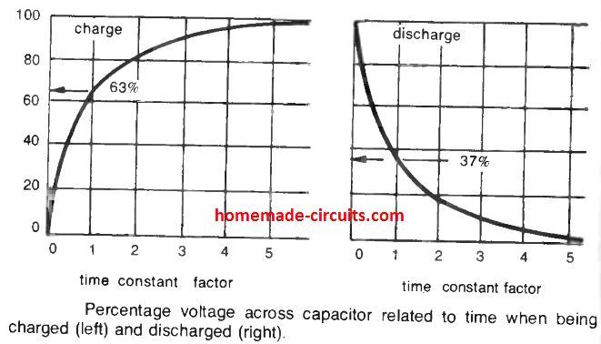
The time constant element signifies the length of time in the form of time factor, for example at 1 time factor of the RC network, 63 % total voltage is accumulated, in a period after 2X time constant, 80% total voltage is built up inside the capacitor; and so forth.
After a time constant of 5 almost (but not quite) 100% voltage may build up across the capacitor. The discharge factors of a capacitor occur in the same fundamental manner but in the inverse sequence.
Meaning, after an interval of time equal to the time constant 5, the voltage applied to the capacitor will achieve a drop of 100 - 63 = 37 % of the full voltage and so forth.
Capacitors are Never Fully Charged or Discharged
Theoretically, at the very least, a capacitor may in no way charge up to the full applied voltage level; neither can it be completely discharged.
In reality, full charge, or total discharge, may be regarded as being accomplished within a time period corresponding to 5 time constants.
Therefore, in the circuit as shown below, powering switch 1 will cause a "full" charge on the capacitor in 5 x time constant seconds.
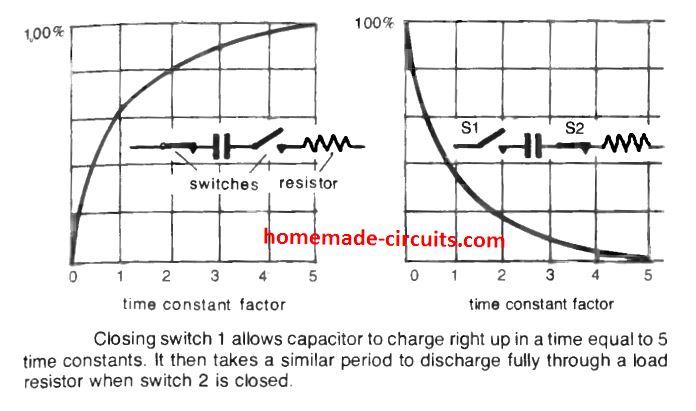
Next, when switch 1 is opened, the capacitor may then be in a situation where it will be storing a voltage equal to the actual applied voltage. And it will hold this charge for an indefinite period of time provided the capacitor has zero internal leakage.
This process of losing charge will be actually extremely sluggish, since in real world no capacitor can be perfect, however for certain significant period of time this stored charge may continue being an effective source of the original "full charge" voltage.
When the capacitor is applied with a high voltage, it can quickly be in a position of delivering an electrical shock in case touched even after the circuit is powered down.
To execute the cycle of charge/discharge as displayed in the second graphical diagram above, when switch 2 is closed, the capacitor begins discharging via the connected resistance, and takes some period of time to accomplish its discharge process.
RC Combination in Relaxation Oscillator
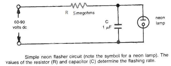
The figure above is a very basic relaxation oscillator circuit operating using the basic charge discharge theory of a capacitor.
It includes a resistor (R) and capacitor (C) wired in series to a dc voltage source. In order to be able to see the working of the circuit physically, a neon lamp is used in parallel with the capacitor.
The lamp behaves virtually like an open circuit until the voltage reaches its threshold voltage limit, when it instantly switches ON and conducts current quite like a conductor and begins glowing. The source of supply voltage for this current hence must be higher than that of the neon triggering voltage.
How it Works
When the circuit is powered ON, the capacitor slowly begins charging as determined by the RC time constant. The lamp begins receiving a rising voltage which is developed across the capacitor.
The moment this charge across the capacitor attains a value which may be equal to the firing voltage of the neon, the neon lamp conducts and begins illuminating.
When this happens the neon creates a discharge path for the capacitor and now the capacitor begins discharging. This in turn causes a drop in the voltage across the neon and when this level goes below the neon's firing voltage, the lamp switches OFF and shuts down.
The process now continues causing the neon to flash ON OFF. The flashing rate or frequency depends on the RC time constant value, which could be adjusted to either enable a slow flashing or fast flashing rate.
If we consider the component values as shown in the diagram, the time constant for the circuit T = 5 (megohms) x 0.1 (microfarads) = 0.5 seconds.
This implies that by changing the RC values, the flashing rate of the neon can be accordingly changed, as per individual preference.
RC Configuration in AC Circuits
When an AC is used in an RC configuration, due to the alternating nature of the current, the one half cycle of the AC charges the capacitor effectively, and likewise it is discharged with the next negative half cycle. This causes the capacitor to alternately charge and discharge in response to the varying polarity of the AC cycle waveform.
Because of this, in effect, AC voltages do not get stored in the capacitor rather is allowed to pass through the capacitor. However, this passage of current is constrained by an existing RC time constant in the path of the circuit.
The RC components decides by how much percentage of the applied voltage the capacitor is charged and discharged. Simultaneously, the capacitor can also provide a slight resistance to the passing of the AC by the way of reactance, even though this reactance basically does not consume any power. Its primary impact is on the frequency response involved in the RC circuit.
RC COUPLING in AC CIRCUITS
Coupling a particular stage of a audio circuit to another stage through a capacitor is a common and widespread implementation. While the capacitance appears to be used independently, it actually may be involved with an integral series resistance symbolized by the term "load" as shown below.
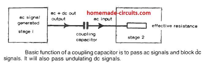
This resistance, aided by the capacitor, gives rise to an RC combination that may be responsible of generating a certain time constant.
It is crucial that this time constant complements the specification of the input AC signal frequency which is being transferred from one stage to another.
If we assume the example of an audio amplifier circuit, the highest range the input frequency could be approximately around 10 kHz. The time period cycle of this sort of frequency will be 1/10,000 = 0.1 milliseconds.
That said, in order to allow this frequency, each cycle implements two charge/discharge characteristics with regards to the coupling capacitor function, which are one positive and one negative.
Therefore the period of time for a solitary charge/ discharge functionality will be 0.05 milliseconds.
The RC time constant required to enable this functioning must satisfy the 0.05 milliseconds value in order to reach the 63 % of the fed ac voltage level, and essentially somewhat less to allow the passage of higher than 63 percent of the applied voltage.
Optimizing RC Time Constant
The above statistics provides us with a idea regarding the the best possible value of the coupling capacitor to be utilized.
To illustrate this, let's say the normal input resistance of a low power transistor can be approximately 1 k. The time constant of a most effective RC coupling might be 0.05 milliseconds (see above), which may be achieved with the following calculations:
0.05 x 10 = 1,000 x C or C = 0.05 x 10⁻⁹ farads = 0.50 pF (or possibly slightly lower, since that would allow higher than 63 % voltage to pass through the capacitor).
Practically speaking, a much larger capacitance value could generally be implemented; which can be as large as 1µF or even more. This may typically provide improved results, but on the contrary may cause reduction in the efficiency of the AC coupling conduction.
Also, calculations suggest that capacitive coupling gets more and more inefficient as the AC frequency increases, when real capacitors are implemented in coupling circuits.
Using RC network in FILTER CIRCUITS
A standard RC arrangement implemented as a filter circuit is demonstrated in the below figure.
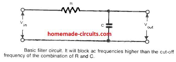
If we look at the input side, we find a resistor attached in series with a capacitive reactance, causing a voltage drop to develop across the two elements.
In case the capacitor reactance (Xc) happens to be higher than R, almost all of the input voltage builds up across the capacitor and therefore the output voltage attains the level equal to the input voltage.
We know that capacitor reactance is inversely proportional to frequency, This implies, if the AC frequency is increased will cause the reactance to decrease, resulting in the output voltage to increase proportionality (but a significant portion of the input voltage will be dropped by the resistor).
What is Critical Frequency
In order to ensure an efficient coupling of AC signal, we have to consider the factor called critical frequency.
At this frequency, the reactance value element tends to get so badly affected that in such condition the coupling capacitor begins blocking the signal instead of efficiently conducting.
In such a situation, the ratio of volts(out) / volts(in) begins declining rapidly. This is demonstrated below in basic diagrammatic form.
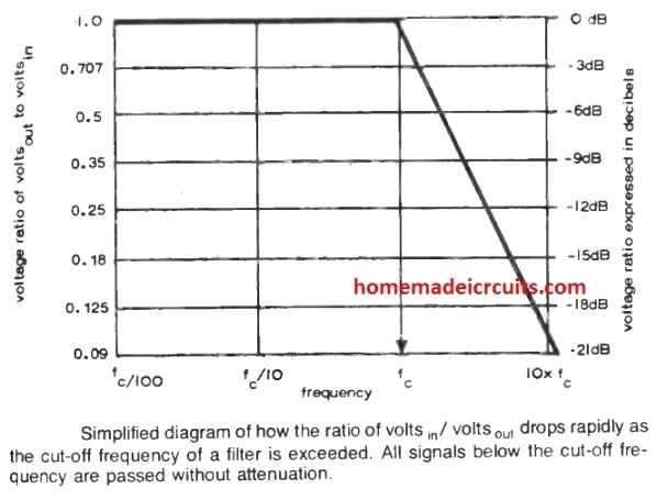
The critical point, called the roll-off point or cut-off frequency (f) is evaluated as:
fc = 1 / 2πRC
where R is in ohms, C is in farads, and π = 3.1416
But from the previous discussion we know that RC = time constant T, therefore the equation becomes:
fc = 1 / 2πT
where T is the time constant in seconds.
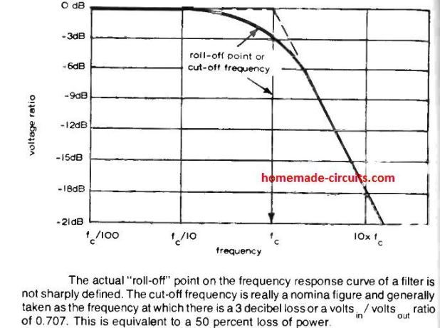
The working efficiency of this type of filter is characterized by their cut-off frequency and by the rate through which the volts(in) / volts(out) ratio begins to drop above the cut-off frequency threshold.
The latter is generally represented as (some) dB per octave (for each frequency doubled), as indicated in the following figure which exhibits the relationship between dB and volts(in) /volts(out) ratio, and also provides an accurate frequency response curve.
RC LOW-PASS FILTERS
As the name suggests, low-pass filters are designed to pass ac signals below the cut-off frequency with minimum loss or attenuation of signal strength. For signals that are above the cut-off frequency, low pass filter generates an increased attenuation.
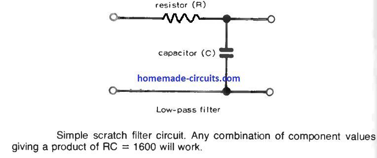
It is possible to calculate exact component values for these filters. As an example, a standard scratch filter normally used in amplifiers could be built to attenuate frequencies over, say, 10 kHz. This specific value signifies the intended cut-off frequency of the filter.
RC HIGH-PASS FILTERS
High-pass filters are designed to operate the other way around. They attenuate frequencies which appear below the cut-off frequency, but allow all frequencies at or above the set cut-off frequency with no attenuation.
To accomplish this high pass filter implementation, the RC components in the circuit are simply swapped with each other as indicated below.
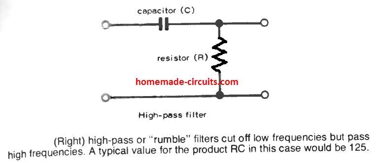
A high pass filter is similar to its low pass counterpart. These are generally employed in amplifiers and audio devices, to get rid of noise or "rumble" generated by the inherent, unwanted low frequencies.
The selected cut-off frequency which is to be eliminated should be low enough so that it doesn't conflict with the "good" bass response. Therefore, the decided magnitude is normally in the range of 15 to 20 Hz.
Calculating RC Cut-off Frequency
Precisely, the same formula is required to calculate this cut-off frequency, thus, with 20 Hz as the cut off threshold we have:
20 = 1 / 2 x 3.14 x RC
RC = 125.
This indicates that as long as the RC network is selected such that their product is 125 will enable the intended high pass cut-off below 20 Hz signals.
In practical circuits, such filters are typically introduced at the preamplifier stage, or in the amplifier immediately before an existing tone control circuit.
For Hi-Fi devices, these cut off filter circuits are usually far more sophisticated than the ones explained here, to enable the cut off points with higher efficiency and pin point accuracy.
.