Basically an SCR ( Silicon Controlled Rectifier) which is also known by the name Thyristor works quite like a transistor.
What SCR Stands for
The device gets its name (SCR) due to its multi layered semiconductor internal structure which refers to the "silicon" word in the beginning of its name.
The second part of the name "Controlled" refers to gate terminal of the device, which is switched with an external signal in order to control the device's activation, and hence the word "Controlled".
And the term "Rectifier" signifies the rectification property of the SCR when its gate is triggered and power is allowed to flow across its anode to cathode terminals, this may be similar to the rectification with a rectifier diode.
The above explanation makes it clear how the device works like a "Silicon Controlled Rectifier".
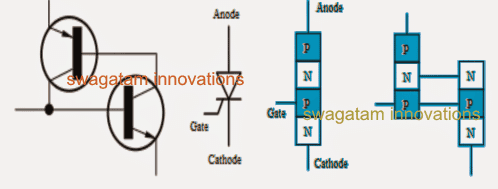
Although an SCR rectifies like a diode, and imitates a transistor due to its triggering feature with an external signal, an SCR internal configuration consists of a four layer semiconductor arrangement (P-N-P-N) which are made up of 3 series PN junctions, unlike a diode which has a 2-layer (P-N) or a transistor which includes a three layer (P-N-P/N-P-N) semiconductor configuration.
You may refer to the following image for understanding the internal layout of the explained semiconductor junctions, and how Thyristors (SCR) work.
Another SCR property that distinctly matches with a diode is it's unidirectional characteristics which allows current to flow only in one direction through it, and block from the other side while it's switched ON, having said that SCRs have another specialized nature which allows them to be operated as an open switch while in the switched OFF mode.
This two extreme switching modes in SCRs restricts these devices from amplifying signals and ths these cannot be used like transistors for amplfying a pulsating signal.
The silicon controlled rectifiers or the SCRs just like Triacs, Diacs, orUJT's which all have the property of performing like rapidly switching solid state AC switches while regulating a given AC potential or current.
So for engineers and hobbyists these devices become an excellent solid state switch option when it comes to regulating AC switching devices such lamps, motors, dimmer switches with maximum efficiency.
An SCR is a 3 terminal semiconductor device which are assigned as Anode, Cathode and the Gate, which in turn are internally made with 3 P-N junctions, having the property to switch at a very high speed.
Thus the device can be switched at any desired rate and discretely set ON/OFF periods, for implementing a particular average switch ON or switch OFF time to a load.
Technically, the layout of an SCR or a thyristor can be understood by comparing it to a couple of transistors (BJT) connected in the back to back order, so as to form like a complementing regenerative pair of switches, as shown in the following image:
Thyristors Two Transistor Analogy


The two transistor equivalent circuit shows that the collector current of the NPN transistor TR2 feeds directly into the base of the PNP transistor TR1, while the collector current of TR1 feeds into the base of TR2.
These two inter-connected transistors rely upon each other for conduction as each transistor gets its base-emitter current from the other’s collector-emitter current. So until one of the transistors is given some base current nothing can happen even if an Anode-to-Cathode voltage is present.
Simulating the SCR topology with a two transistor integration reveals the formation to be in a manner such that the collector current of the NPN transistor is supplying straight to the base of the PNP transistor TR1, while the collector current of TR1 is connecting the supply with the base of TR2.
The simulated two transistor configuration seem to interlock and complement each others conduction by receiving the base drive from the collector emitter current of the other, this makes the gate voltage very crucial and ensures that the shown configuration can never conduct until a gate potential is applied, even in the presence of the anode to cathode potential may be persistent.
In a situation when the device's anode lead is more negative than its cathode, allows the N-P junction to remain forward biased, but ensuring the outer P-N junctions to be reverse biased such that it acts like a standard rectifier diode.
This property of an SCR enables it to block a reverse current flow, until a significantly high magnitude of voltage which may be beyond its beak down specs is inflicted across the mentioned leads, which forces the SCR to conduct even in the absence of a gate drive.
The above refers to a critical characteristics of thyristors which can causes the device to get triggered undesirably through a reverse high voltage spike and/or an high temperature, or a rapidly increasingly dv/dt voltage transient.
Now suppose in a situation where the Anode terminal experiences more positive with regards to its cathode lead, this helps the outer P-N junction to become forward biased, although the central N-P junction continues to remain reverse biased. This consequently ensures that the forward current is also blocked.
Therefore in case a positive signal induced across the base of the NPN transistor TR2 results the passage of the collector current towards the base f TR1, which in trun forces the collector current to pass towards the PNP transistor TR1 boosting the base drive of TR2 and the process gets reinforced.

The above condition allows the two transistors to enhance their conduction until the point of saturation owing to their shown regenerative configuration feedback loop which keeps the situation interlocked and latched.
Thus as soon as the SCR is triggered, it allows a current to flow from its anode to cathode with only a minimal forward resistance of around coming in the path, ensuring an efficient conduction and operation of the device..
When subjected to an AC, the SCR may block both the cyles of the AC until the SCR is offered with a triggering voltage across its gate and cathode, which instantly allows the positive half cycle of the AC to pass across the anode cathode leads, and the device begins imitating a standard rectifier diode, but only as long as the gate trigger stays switched ON, the conduction breaks the moment gate trigger is removed.
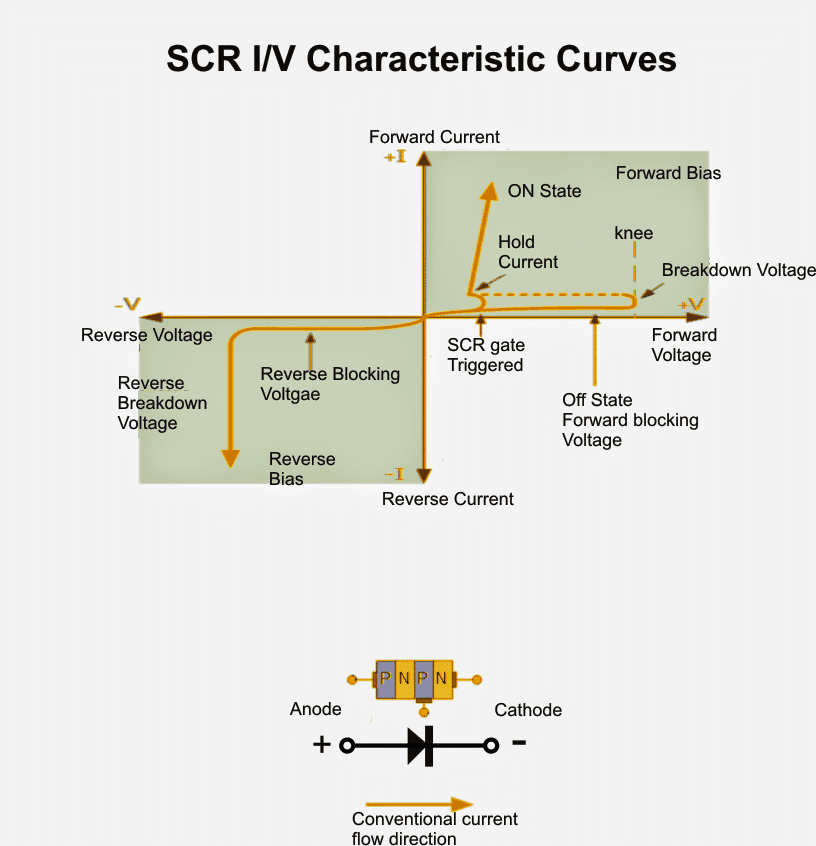
The enforced voltage-current or I-V characteristics curves for the activation of a silicon controlled rectifier may be witnessed in the following image:
Thyristor I-V Characteristics Curves

However For a DC input, as soon as the thyristor is triggered ON, due to the explained regenerative conduction it undergoes a latching action such that the anode to cathode conduction holds on and keeps conducting even if the gate trigger is removed.
Thus for a DC power the gate completely loses its influence once the first triggering pulse is applied across the gate of the device ensuring a latched current from its anode to cathode. It may be broken by momentarily breaking the anode/cathode current source while the gate is completely inactive.
SCR cannot Work like BJTs
SCR are not designed to be perfectly analogue like the transistor counterparts, and therefore cannot be made to conduct at some intermediate active region for a load which may be somewhere between complete conduction and compete switch OFF.
This is also true because the gate trigger has no influence on how much the anode to cathode can be made to conduct or saturate, thus even a small momentary gate pulse is enough to swing the the anode to cathode conduction into a full switch ON.
The above feature enable an SCR to be compared and considered like a Bistable Latch possessing the two stable states, either a complete ON or a complete OFF. This is caused due to the two special characteristics of the SCR in response to an AC or a DC inputs as explained in the above sections.
How to Use the Gate of an SCR to Control its Switching
As discussed previously, once an SCR is triggered with a DC input and its anode cathode is self latched, this may be unlocked or switched OFF either by momentarily removing the anode supply source (anode current Ia) fully, or by reducing the same to some significantly low level below the specified holding current of the device or the "minimum holding current" Ih.
This implies that thr Anode to Cathode minimum holding current should be reduced until the thyristors internal P-N latching bond is able to restore its natural blocking feature into action.
Therefore this also means that in order to make an SCR work or conduct with a gate trigger it's imperative that the anode to cathode load current is over the specified "minimum holding current" Ih, otherwise the SCR might fail to implement the load conduction, therefore if IL is the load current, this must be as IL > IH.
However as already discussed in the previous sections, when an AC is used across the SCR Anode.Cathode pins, ensures that the SCR is not allowed to execute the latching effect when the gate drive is removed.
This is because the AC signal switches ON and OFF within its zero crossing line which keeps the SCR anode to cathode current to turn off at every 180 degrees shift of the positive half cycle of the AC waveform.
This phenomenon is termed as "natural commutation" and imposes an crucial feature to an SCR conduction. Contrary to this with DC supplies this feature becomes immaterial with SCRs.
But since an SCR is designed to behave like a rectifier diode it responds effectively only to the positive half cycles of an AC and remains reversed biased and entirely unresponsive to the other half cycle of the AC even in the presence of a gate signal.
This implies that in the presence of a gate trigger, the SCR conducts across its anode to cathode only for the respective positive AC half cycles and stays muted for the other half cycles.
Due to the above explained latching feature and also the cut-of during the other half cycle of an AC waveform, the SCR can be effectively used for chopping phase AC cycles such that the load can be switched at any desired (adjustable) lower power level.
Also known as phase control, this feature can be implemented through an external timed signal applied across the gate of the SCR. This signal decides after how much delay the SCR may be fired once the AC phase has commenced its positive half cycle.
So this allows only that portion of the AC wave to be switched which is being passed after the gate trigger..this phase control is among the main features of a silicon controlled thyristor.
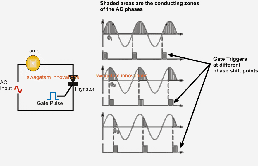
How thyristors (SCR) work in phase control may be understood by looking at the images below.
The first diagram shows an SCR whose gate is permanently triggered, as may be seen in the first diagram this allows the complete positive waveform to get initiated from start to finish, that from across the central zero crossing line.
Thyristor Phase Control

At the outset of each positive half-cycle the SCR is “OFF”. On the induction of the gate voltage activates the SCR into conduction and allows it to be entirely latched “ON” throughout the positive half cycle. When the thyristor is switched on at the start of the half-cycle (θ = 0o), the connected load (a lamp or any similar) would be “ON” for the whole positive cycle of the AC waveform (half-wave rectified AC) at an elevated average voltage of 0.318 x Vp.
As the initialization of the gate switch ON is raised along the half cycle (θ = 0o to 90o), the connected lamp is lighted for a smaller amount time and the net voltage brought to the lamp likewise proportionally less dropping its intensity.
Subsequently it is easy to exploit a silicon controlled rectifier as an AC light dimmer and in many different additional AC power applications for example: AC motor-speed control, heat control devices and power regulator circuits, and so on.
Up till now we have witnessed that a thyristor is fundamentally a half-wave device that is able to pass current in only the positive half of the cycle whenever the Anode is positive and prevents current flow just like a diode in cases where the Anode is negative, even if the gate current remains active.
Nevertheless you may find many more variants of similar semiconductor products to choose from which originate under the title of “Thyristor” designed to operate in both directions of the half cycles, full-wave units, or could be switched “OFF” by the Gate signal.
This kind of products incorporate “Gate Turn-OFF Thyristors” (GTO), “Static Induction Thyristors” (SITH), “MOS Controlled Thyristors” (MCT), “Silicon Controlled Switch” (SCS), “Triode Thyristors” (TRIAC) and “Light Triggered Thyristors” (LASCR) to identify a few, with so many of these devices accessible in many different voltage and current ratings which makes them interesting to be used in purposes at very high power levels.
Thyristor Working Overview
Silicon Controlled Rectifiers known generally as Thyristors are three-junction PNPN semiconductor devices that could be considered two inter-connected transistors which you can use in the switching of mains operated heavy electrical loads.
They are characterized to be latched-“ON” by a single pulse of positive current applied to their Gate lead and can keep on being “ON” endlessly until the Anode to Cathode current is reduced below their specified minimum latching measure or reversed.
Static Attributes of a Thyristor
Thyristors are semiconductor equipment configured to function only in the switching function. Thyristor are current controlled products, a tiny Gate current is able to control a more substantial Anode current. Enables current only once forward biased and triggering current applied to the Gate.
The thyristor operates similar to a rectifyier diode whenever it happens to be activated “ON”. Anode current has to be more than sustaining current value to preserve conduction. Inhibits current passage in case reverse biased, irrespective of whether or not Gate current is put on.
As soon as turned “ON”, gets latched “ON” performing regardless if a gate current being applied but only in case the Anode current is above latching current.
Thyristors are fast switches which you can use to substitute electromechanical relays in a number of circuits as they simply do not have any vibrating parts, no contact arcing or have problems with deterioration or grime.
But additionally to simply switching substantial currents “ON” and “OFF”, thyristors can be accomplished to manage the RMS value of an AC load current without dissipating a considerable amount of power. An excellent example of thyristor power control is in the control of electrical lighting, heaters and motor speed.
In the next tutorial we will look at some basic Thyristor Circuits and applications using both AC and DC supplies.
dear sir,
please I need a thyristor circuit to feed an ac transformer from a capacitor bank of 50 volts
kindest regards
Hello Alain, can you please provide more details about the working of your circuit, then i can design it correctly…
Hi Swagatam;
Load is a Fan DC 12V and 0.32 Amp. My system will be on all day long. There are 2 selections for me; 1) Fan will be on all day long or 2) will be on and off app. 500 times in a day. As a result I think all selections are not good but second one is better than the first. So then I think thyristor is better than relay too and 4N25 is OK for the purpose. I need your comment and please advise circuit diagram if available.
Thanks and Regards.
Hi Suat,
For a DC load or DC supply, an SCR or thyristor cannot be used, because as per the internal characteristics of the device it will latch and permanently switch ON the load once the SCR is triggered. You can use a BJT or a MOSFET instead.
hi dear sir we have a number of medium frequency furnaces in our company,and one of our main problem is burning thyristors ,and most burn as dots and spots and i think that our SNUBBER circuit may have a problem ،can you suggest a good circuit and a snubber to control rhyristors i must mention that our rhyristors belong to WESTCOD company and with the gate turn off specification i mean GTO THYRISTOR that can be controlled
Hi Sedigh, For a resistive load a snubber may not be required. Snubber is required only for inductive loads.
A GTO can be avoided by applying zero voltage switching through special opto coupler based triggering devices:
https://www.mouser.com/datasheet/2/149/MOC3031M-195882.pdf
hi dear sir excuse me i forget to say i meant inductive furnace,i meant my output has an inductor and a capacitor that includes a resonant or tank circuit and must detect the existence of a resonant circuit through current consumption . .
and power input to the thyristors is DC source and a total 8 thyristors are paired together perhaps for added safety and security ,that means push pull circuit of with 8 thyristors ,so my load is inductive and the presence of snubber is necessary my biggest problem is turning off the thyristors, of course in my opinion ,GTO’s thyristors are turned on and reverse by isolated Tiny transformers and their shutdown is simulated by a power outage of the isolated transformer and the inductive of electricity in reverse mode the the thyristors leads to their shutdown.
Yes thyristors and SCRs can be turned off instantly by using pulse transformers at the gate. The standard snubber circuit involves RC network across the anode/cathode of the SCR, along with an MOV at the input side. But I cannot provide the exact details about the part values.