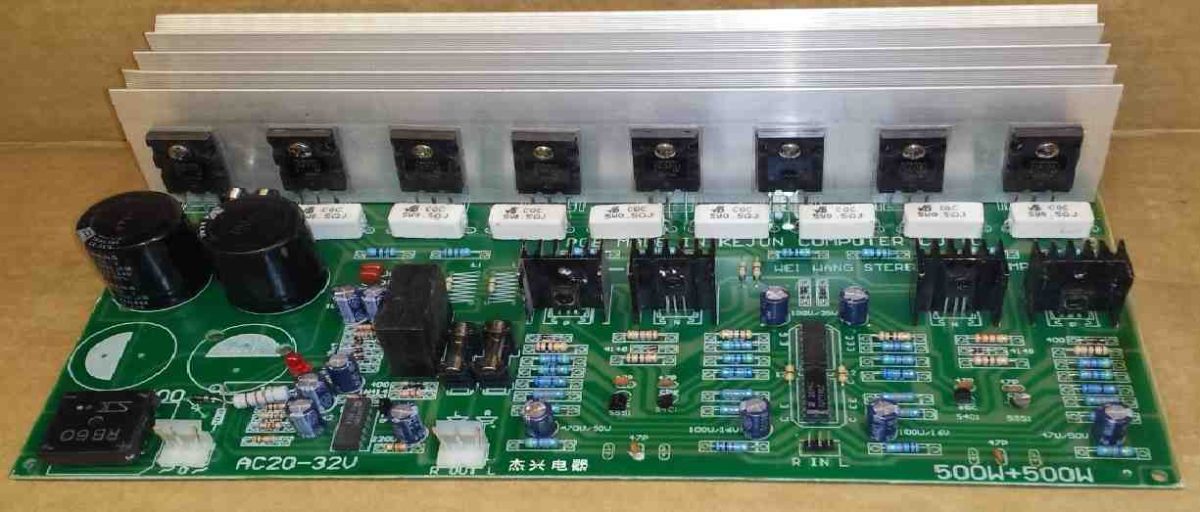
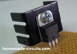
Heatsinking is critical for power devices in circuits that are intended to maximize their performance. When heat from the power devices cannot be moved away very quickly, the power devices and its operating elements could be damaged. You may calculate how hot your semiconductors could become while operating, using a couple of easy formulas. Using formulas gets rid of guesswork and the anxiety that comes with it about making a mistake, should you guess incorrectly.
Heatsinks are normally used for absorbing and dissipating excessive heat from electronic power devices such as transistors, SCRs, triacs etc, so that the device temperature can be controlled below their maximum tolerable limit.
The metal aluminum is normally used as the heatsink material due to its excellent heat conductivity, and relatively lower price compared to other metals like copper.
The size of the heatsink determines how quickly and optimally the heat from the devices can be absorbed and dispersed into the air.
If the selected heatsink is too small, it may fail to accomplish the intended cooling, and if it's too large, it can affect the compactness and cost of the electronic circuit.
In order to ensure an optimally sized heatsink for a semiconductor device, it is always recommended to calculate the parameters accurately using formulas, so that a fairly accurate heatsink dimension can be determined.


Convection
Natural convection can be defined as the heat transfer process through the circulation of gas or fluid. In our case this happens via ambient air at room temperature, and this is the design objective applied for cooling semiconductors.
In electronic devices, the convection heat transfer is proportional to the surface area of metal exposed, the force of air moving across the device surface, and the temperature differential between the two.
While considering heatsinks, the power semiconductor is regarded a component.
Thus, the heat equivalent in watts generated by the device is equal to the voltage drop across it, multiplied by the current flowing through it, multiplied by the time factor (percentage of time it is switched ON, divided by 100). And this is the absolute temperature that the heatsink should disperse into the atmosphere.
This is a quick calculation for a basic linear power-supply semiconductor. The equation for a semiconductor power switching transistor can be a lot more complicated.
In the case of an audio amplifier, we may need to calculate dissipation. In any scenario, you may want to be as exact and conservative as possible while calculating the heat to be dissipated equivalent to the heat in watts.
Try looking up the junction-to-case thermal impedance and case-to-sink thermal impedance on the datasheet for the semiconductor device you'll be mounting on a heatsink.
These impedance magnitudes can be found in °C per watt. This means that for every watt of heat power dissipated by the junction, this will be a certain amount of °C higher than the case temperature, and vice versa.
If you want to maintain the device junction temperature at or below 100° C, and its datasheet junction-to-case thermal impedance value is 10°C/watt, then a power output of 7.5 watts might cause the junction temperature to rise to 100° C. This might happen even if the case temperature is maintained at a constant 25° C (possibly by subjecting the device to flowing water).
For something like an International Rectifier IRFZ40 MOSFET, common junction-to-case thermal impedances (ZJC) is 1° C/W, and and this is 1.52° C/W for the BJT 2N3055.
The case-to-sink thermal impedance (Zcs) for a TO-220 case is 1° C/W, and for a TO-3 case this is 0.12° C/W. Whenever you are unable to access a particular device's datasheet, you can try estimating the junction-to-case thermal impedance for your specific semiconductor device using the above mentioned figures as a reference.
Heatsink Design Parameters
What is the highest temperature that the junction of a transistor could reach? Several circuit designers fix the maximum junction temperature of a semiconductor device at 80° C.
This is because, higher temperatures than this can severely impair the device properties, and can lead to a thermal runaway situation, a serious risk for bipolar transistors.
Always treat the manufacturer's datasheet comments about maximum watt values and junction temperature with a grain of salt. These results are only applicable if the device is constantly cooled to a comfortable temperature of 25° C.
Understanding Ambient Temperature and Heatsink Temperature
What does ambient temperature exactly suggest? Remember that the transistor could be enclosed inside a box, in which other heat-dissipating devices may be adding to the ambient air temperature. If you are confident that normal room airflow is able to freely move across the devices, you can anticipate 25° C to be the ambient temperature value, however you may have to very cautious.
Keep in mind that during the summer, the ambient temperature may rise to 100° F = 38° C. With these data in hand, you could calculate ΔT, or the predicted temperature differential between the yet-to-be known heatsink size and the air that would facilitate cooling.
ΔT = TMaxJ - [Wj x ( Zjc + Zcs)] -TAA
where ZJC represents the junction-to-case thermal impedance, Zcs symbolizes the case-to-sink thermal impedance, TAA denotes the ambient air temperature, TMJ defines the highest junction temperature, and Wj indicates the junction wattage.
Let's assume we wish to use a 2N3055 transistor to drive a motor that draws 3 amps. You might notice that the transistor drops 1.2 volts at this magnitude of current, and you might also notice that the highest duty cycle is 50%, or 0.5.
As a result, the power dissipated will be 3 x 1.2 x 0.5 = 1.8 watts. If you go with a maximum junction temperature of 80° C and a minimum junction temperature of 25° C, ambient air, then ΔT can be calculated as follows:
ΔT = 80 - [1.8 x (1.52 + 0.12)] - 25
ΔT = 52° C
Under such situations, the ΔT calculation indicates that the projected heatsink may be at least 52° C warmer than the air. Therefore, how big should this heat sink be?
The following formula is used to determine the solution:
A = (WJ x 5630) / ΔT5/4
where A indicates the area of the heatsink vertical surface in cm2. If you want to calculate it with in2, you can use the following formula:
A = (WJ x 872.6) / ΔT5/4
Considering the 2N3055 BJT example, and by applying the above in2 equation, we get the following results:
A = (1.8 x 872.6) / 525/4
A = 11.2 in2
The result shows that a heatsink with at least 11.2 square inches of vertical surface area exposed in free air would be necessary to cool the 2N3055 transistor.
Heatsink for Parallel Transistors
Now suppose you want to put two or more semiconductor devices with similar characteristics on the single common heatsink (in parallel), so that they consume equivalent currents.
To implement this you may calculate the thermal power of the pair and divide the thermal impedances by the number of devices, assuming them to be a single device. Semiconductor devices with dissimilar specifications should be placed on separate heatsinks.
MOSFETs in Parallel
Let's consider this example. In a low-voltage switching power supply, two IRFRZ40 power MOSFETs are wired in parallel. Currents are expected to reach 40 amps via the two MOSFETs, and duty cycles may exceed 80 percent. At 80° C, the IRFZ40's on-resistance (FET conducting) might be around 0.036 ohm. Therefore, the parallel pair will have a resistance of 0.018 ohm to the 40 amps, yielding 0.018 x 40 x 0.8 = 23 watts. Imagining a worst-case temperature of 38° C, for example the ambient conditions of a desert, during summer, we can estimate the heatsink dimensions as given below:
ΔT = 80 - [23 x (0.5 + 0.5)] - 38
ΔT = 19° C
The above result specifies that the heatsink temperature may be 19° C more hotter than the ambient temperature
Now, using the above data we can determine the optimum heatsink size using the following calculations:
A= (23 x 872.6) / 195/4
A = 506 square inches.
The 506 square inches result might appear too large, however a normal big heatsink measuring 5 x 4 x 25/8 inches with a surface area of 250 square inches might require an additional one to effectively dissipate the heat.
Obviously , such large heatsinks may be costly, and if the cost is higher than the device itself, you might need to reconfigure the circuit using more number of parallel transistors. This method might reduce the device conducting resistance and thus the amount of heat that must be dissipated.
Hi Mr. Swagatam;
We had handled the heat sink subject at the “Dummy Load” article. The heat sink (that I used in my circuit) dimension is 6 cm x 5 cm for the TIP3055. I do not use any fireproof rubber-teflon material or paste over the heat sink (or rear the TIP3055) since there is no other component in contact with the heat sink but only TIP3055. Please advise if it is acceptable or not?
Hi Suat,
Yes 6 x 5cm heatsink looks good to me, however, it would better if it is finned type heatsink….teflon isolator is not required.
" rel="ugc">
Hi dear Swagatam. Thank you so much for placing this article which is very useful, on your valuable site. Wish you all the good things.
Bye
Veronika
Thank you Veronika, wish you all the best!