TSOP17XX series devices are advanced infrared sensors having a specified center frequency of operation which makes their detection extremely reliable and foolproof.
In this post I have explained how to connect a TSOP series infrared sensor and use it for a specified IR remote control operations.
TSOP IR Sensor Specifications
A TSOP series of IR sensor ICs may consist many variants which differ marginally from each other, these may be in the form of TSOP22.., TSOP24.., TSOP48.., TSOP44..
However the most popular and most commonly used is the TSOP1738 IC module which is from the TSOP17XX series.
The other variants from this group are available with the following numbers:
TSOP1733, TSOP1736, TSOP1737, TSOP1740, TSOP1756, TSOP1738CB1, TSOP1738GL1, TSOP1738KA1, TSOP1738KD1, TSOP1738KS1, TSOP1738RF1, TSOP1738SA1, TSOP1738SB1, TSOP1738SE1, TSOP1738SF1, TSOP1738TB1, TSOP1738UU1, TSOP1738WI1, TSOP1738XG1, TSOP1740, TSOP1740CB1, TSOP1740GL1, TSOP1740KA1, TSOP1740KD1, TSOP1740KS1, TSOP1740RF1.
All the above TSOP variants have identical features and characteristics except their center working frequency, which may typically range between 30 kHz to 60 khZ.
How the Connect TSOP1738 sensors
Connecting or wiring a TSOP1738 infrared sensor is actually very easy, once you know how it responds to supply voltage and the IR signals applied across its specified pinouts.
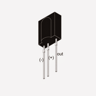
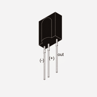
The diagram below shows the a standard TSOP infrared sensor IC, whose pinouts can eb seen marked as (-), (+) and the OUT.
The (+) and the (-) are the supply pins of the IC and are specified to be connected across a 5V typical supply level, to be precise any voltage between 3 and 6V may be aplied here, although 5V works the best, and is recommended since it can be easily tailored using a 5V regulator IC 7805 and allows a wide range of input to be used (between 6V and 24V).
The curved lens which can be seen over the central portion of sensor body is where the infrared signal from a remote control handset is focused for enabling the TSOP to initiate its sensing operations.
Sensor Pinouts
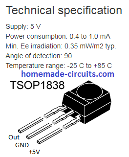
NOTE: The pinout polarity is different for the TSOP1838 IR detector, as shown below. So please verify the pinout sequence if you are using a different variant of the IC.
How connect Supply Voltage to TSOP1738
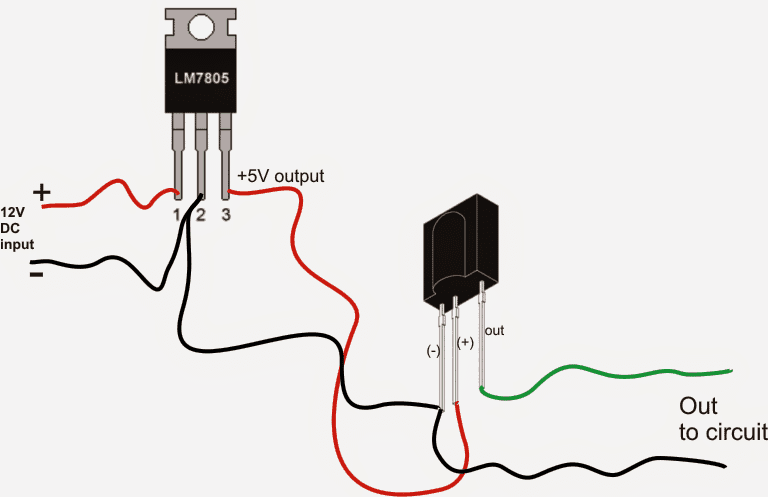
The following image shows how the TSOP1738 IC needs to be wired and connected across a given supply voltage and how its output may be terminated to the relay driver circuit for the intended toggling of the relay according to the sensor's response to the IR signal.
The shown wire connections are for indicative purpose only, these could be in practice connected through PCB tracks.
How TSOP1738 Responds to Infrared Signal
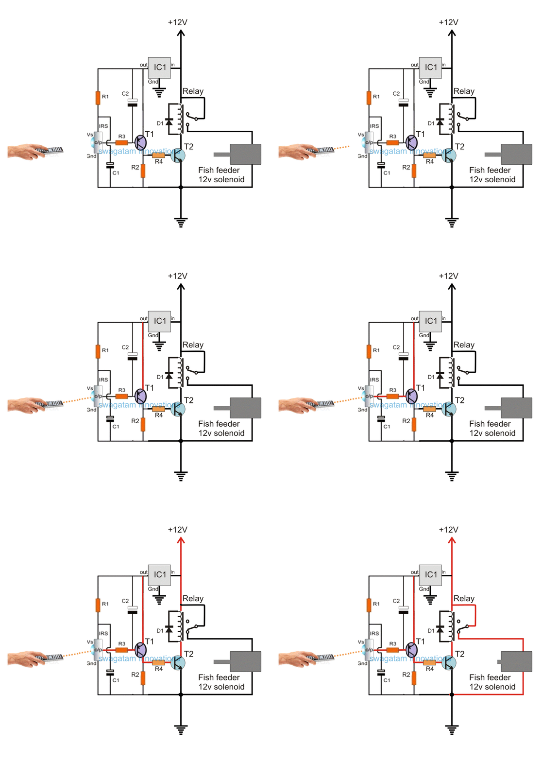
I have explained step wise how a wired TSOP1738 sensor behaves or responds when an IR signal is focused towards its lens.

In the above diagram we see that as long as the supply input is not connected to the TSOP circuit, its output stays dormant or inactive, meaning it's neither positive nor negative.

Video Clip

Initially the Output is a +5V (Supply Level)
As soon as the TSOP is applied with a supply voltage (via a 5V regulator), it responds by making its output pin high or at the positive (+5V) level.
This level is maintained, as long as an input infrared signal is not pointed or is focused towards the lens of the TSOP

When an IR Signal is Applied
In the above diagram we can see IR signal frequency being applied and approaching the lens of the TSOP, until it touches the lens of the sensor.
The moment the IR signal reaches the lens of the TSOP, the output of the TSOP begins responding and oscillating in tandem with the focused infrared signal.
Remember, the input IR frequency focused towards the TSOP sensor must be oscillated at a 38 KHz frequency, otherwise the TSOP sensor will not respond. This frequency may be slightly different for the different variants of the TSOP sensors.
The Output Waveform of the Sensor
The output waveform indicates how the output of the IC oscillates between a positive (initial status) and negative (sensing status) across its "OUT" pins in an alternating pattern, as long as the input IR is kept focused towards it.
How to configure the above response from the TSOP1738 sensor for driving a relay stage.
A classic example may be seen in the following diagram taken from the article "remote controlled fish feeder", where we can see the TSOP being used for an IR remote control application and for a toggling action in response to an IR input triggering signal.
Basic Connection Details of TSOP1738 in a Circuit
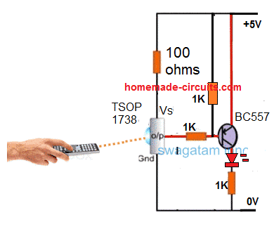
Simplified Design
Application Schematic for TSOP1738 Relay Operation
Parts List
- R1, R3 = 100 ohms
- R4, R2 = 10K
- T1 = BC557
- T2 = BC547
- Relay 12V, 400 ohms
- IC = 7805
- D1 = 1N4007
- Sensor = TSOP17XX
- C1, C2 = 22uF/25V
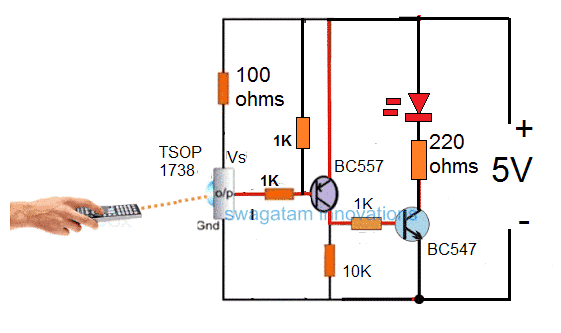
Here we can see that a PNP transistor is being used for toggling the relay, I have explained why exactly a PNP device is required for toggling a TSOP sensor, why an NPN BJT may not be suitable for the same.
Through the above explanation we understood the fact that while the TSOP is in the standby mode or as long as there's no IR signal focused, the output from the device holds a positive potential.
This implies that if an NPN was used in conjunction with this output then this would force the transistor to remain switched ON in the standby mode, and switch it OFF in the presence of an IR signal....
This is technically incorrect because this would keep the relay switched ON all the time and switched OFF only while an IR signal was triggered...this condition is not recommended and therefore we use a PNP transistor which inverts the response from the TSOP sensor and toggle the relay ON only in response to an IR signal, and keeps the relay switched OFF normally while the sensor is in the standby mode (no IR signal).
Here C2 is used to filter the ripples or the pulsating DC output of the TSOP, so that the transistors activate properly and without causing a chattering effect on the relay
