In this article I have explained a very simple method of acquiring 220V DC from a 12V DC source. The idea utilizes inductor/oscillator based boost topology with the help of the IC 555.
Circuit Operation
Referring to the circuit diagram below, we see that the entire idea is based upon the versatile, evergreen IC 555.
Here it's configured in its standard astable multivibrator mode for generating the required pulses at a frequency determined by the resistors 4k7, 1k and the capacitor 680pF.
The duty cycle may be appropriately adjusted by experimenting the 1K resistor.
The output is received at pin#3 of the IC, which is fed to the gate of an N-channel mosfet.
When power is switched ON, the positive pulses emanating from pin#3 switch ON the mosfet into full conduction.
During the above periods the 12V high current potential is pulled to ground via the coil by the mosfet.
As we all know inductors always try to oppose instant changes in current polarity through it, therefore during the negative pulses when the mosfet remains switched OFF, forces the coil to dump the stored potential in it in the form of high voltage EMF pulse into the output.
This voltage may be equal to 220V DC and gives rise to the required potential at the shown outlet of the circuit.
The above straightforward operation is repeated continuously at the given frequency providing a sustained 220V DC at the output.
The BC547 and its base network is introduced for limiting the output voltage to the required degree.
For example if the required output is 220V, the 47K preset may be adjusted such that the220V mark never exceeds, irrespective of the coil back emf rate or the input voltage fluctuations.
The mosfet can be any 30V, 50 amp type, for example a NTD4302 may be used.
The coil wire should be thick enough to hold up to 30 or more amps.
Circuit Diagram

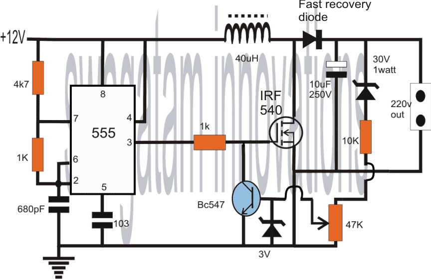
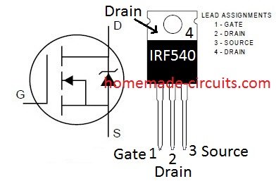
NOTE: THE MOSFET IS MISTAKENLY SHOWN AS IRF540, WHICH IS NOT APPROPRIATE FOR THIS APPLICATION, SO PLEASE REPLACE IT WITH AN IRF840 MOSFET.
WARNING: THIS CIRCUIT INVOLVES HIGH VOLTAGE, EXTREME CAUTION IS ADVISED WHILE HANDLING THIS CIRCUIT.
IC 555 Pinout Details


Mosfet IRF 540 Pinout Details