

In this post I have explained the circuit for a simple, universal capacitive discharge ignition circuit or a CDI circuit using a standard ignition coil and a solid state SCR based circuit.
How Ignition System in Vehicles Work
The ignition process in any vehicle becomes the heart of the entire system as without this stage the vehicle just won’t start.
To initiate the process, earlier we used to have the circuit breaker unit for the required actions.
Nowadays the contact-breaker is replaced with a more efficient and long lasting electronic ignition system, called the capacitor discharge ignition system.
Basic Working Principle
The basic working of a CDI unit is executed through the following steps:
- Two voltage inputs are fed to the electronic CDI system, one is high voltage from the alternator in the range of 100 V to 200 V AC, other is a low pulse voltage from a pickup coil in the range of 10 V to 12 V AC.
- The high voltage is rectified and the resultant DC charges a high voltage capacitor.
- The short low voltage pulse drives an SCR which discharges or dumps the capacitor's stored voltage into the primary of an ignition transformer or coil.
- The ignition transformer steps up this voltage to many kilo-volts and feeds the voltage to the spark-plug for creating the sparks, which finally ignites the combustion engine.
Circuit Description
Now let’s learn the CDI circuit operations in detail with the following points:
Basically as the name suggest, ignition system in vehicles refers to the process in which the fuel mixture is ignited for initiating the engine and the drive mechanisms. This ignition is done through an electrical process by generating high voltage electrical arcs.
The above electrical arc is created through extreme high voltage passage across two potentially opposite conductors through the enclosed air gap.
As we all know that for generating high voltages we require some kind of stepping up process, generally done through transformers.
As the source voltage available in two wheeler vehicles is from an alternator, may not be powerful enough for the functions.
Therefore the voltage needs to be stepped up many thousand folds in order to reach the desired arcing level.
The ignition coil, which is very popular and we all have seen them in our vehicles is especially designed for the above stepping up of the input source voltage.
However the voltage from the alternator cannot be directly fed to the ignition coil because the source may be low in current, therefore we employ a CDI unit or a capacitive discharge unit for collecting and releasing the alternator power in succession in order to make the output compact and high with current.
PCB Design

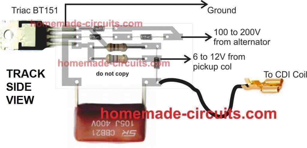
CDI Circuit using an SCR, a few Resistors and Diodes
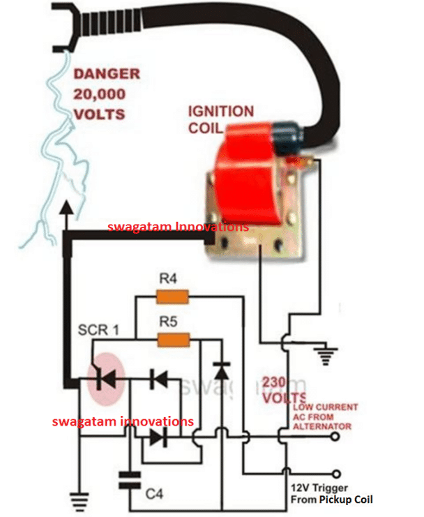
Referring to the above capacitor discharge ignition circuit diagram, we see a simple configuration consisting of a few diodes, resistors, a SCR and a single high voltage capacitor.
The input to the CDI unit is derived from two sources of the alternator. One source is a low voltage around 12 volts while the other input is taken from the relatively high voltage tap of the alternator, generating around a 100 volts.
The 100 volts input is suitably rectified by the diodes and converted to 100 volts DC.
This voltage is stored inside the high voltage capacitor instantaneously. The low 12 voltage signal is applied to the triggering stage and used for triggering the SCR.
The SCR responds to the half wave rectified voltage and switches the capacitors ON and OFF alternately.
Now since the SCR is integrated to the ignition primary coil, the released energy from the capacitor is forcibly dumped in the primary winding of the coil.
The action generates a magnetic induction inside the coil and the input from the CDI which is high in current and voltage is further enhanced to extremely high levels at the secondary winding of the coil.
The generated voltage at the secondary of the coil may rise up to the level of many tens of thousands of volts. This output is appropriately arranged across two closely held metal conductors inside the spark plug.
The voltage being very high in potential starts arcing across the points of the spark plug, generating the required ignition sparks for the ignition process.
Parts List for the CIRCUIT DIAGRAM
R4 = 56 Ohms,
R5 = 100 Ohms,
C4 = 1uF/250V
SCR = BT151 recommended.
All Diodes = 1N4007
Coil = Standard two-wheeler ignition Coil
The following video clip shows the basic working process of the above explained CDI circuit. The set up was tested on table, and therefore the trigger voltage is acquired from a 12V 50Hz AC. Since the trigger is from a 50Hz source, the sparks can be seen arcing at the rate 50Hz.
