In this post I have explained a simple method for making an inexpensive LED name plate with illuminated back light, which can be made by incorporating only 4 LEDs and yet acquire a dazzling back light illumination for the name plate.
Introduction
LEDs are no doubt gaining popularity by leaps and bounds and probably most of the illuminated decorative articles today incorporate LED as the light source.
These devices are relatively cheap, extremely bright and outstandingly efficient with their operations.
Digital displays today also incorporate LED technology and we all know how impressive they look with the involved digits distinctly visible with an illuminated back light.
The back illumination especially gives a fuller look and helps to highlight the display in a better way.
However these displays can be pretty expensive and require microcontroller ICs for producing the involved illuminations. A new hobbyist may find it difficult to grasp and make such displays at home.
Using LEDs in series for designing alphanumerical displays consisting of the desired names and numbers looks good but these don't produce the effects which is generally obtained from a back illuminated displays.
Creating Back Illumination
A cheap way of making a back illuminated display or a name plate having the desired alphabets is explained here, let's see how we can implement the whole concept very cheaply.
For making the proposed back illuminated name plate circuit design we will basically require the following very few of the components.
Four high bright LEDs, color will depend on the user preference, I used blue LEDs in my prototype because my party wanted blue back light illumination for his displays.
A rectangular plastic lens, made up of acrylic material.
PCB as shown in the figure.
Positive film of the desired name or, a screen printed film with the name portion kept transparent while the rest of the area painted black and opaque.
150 Ohm resistor, 1 no.
Refer circuit diagram
How to Make the Display.
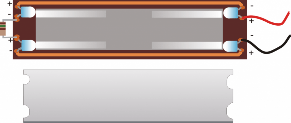
Connect the LEDs and the resistor as shown in the figure below such that the LEDs focus the light across the length of the rectangular PCB.
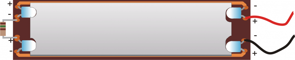
Cut the acrylic lens such that it perfectly fits in between the LEDs, make notches or grooves at the lens ends for making a snug fitting with the LEDs.
Now scratch one of the surfaces of the acrylic lens with a polish paper or an emery paper, such that it becomes rough and grainy on that surface and almost opaque for a clear vision, this operation is the secret behind producing a perfect and uniform back light.
Place a white paper cut to size on the PCB such that the light from the LEDs floods the white paper across the length.
Next place the lens in the center of the LED, over the PCB and the above white paper with its roughened surface on the top side.
Next place the positive film of the name display over the above lens.
Switch ON power to the LEDs, wow! your name plate is glowing bright with an illuminated back-light that's uniformly lit across the whole displayed name.
Put insulation tape over the side ends of the unit such that light does not escape from these areas.
Enclose the whole unit inside a suitable rectangular box for displaying it in the preferred location.
PCB, LED and the Lens Set Up

Lens Placed over the PCB
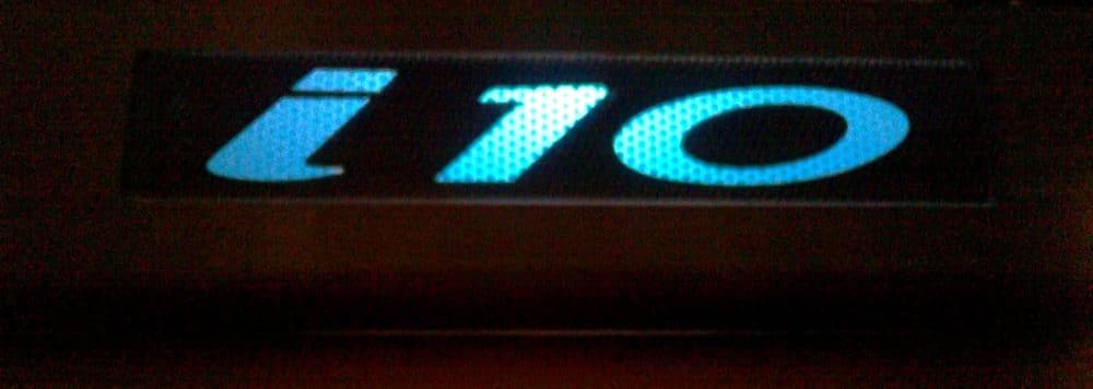
Example film positive of a particular display name:

Positive film of the name placed over the lens for the final illuminated get-up:

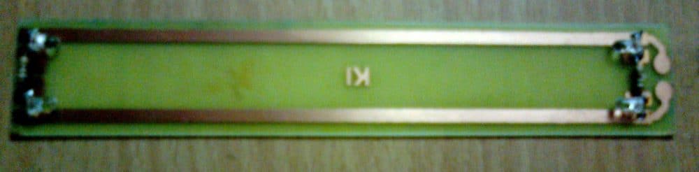
Now some glimpses of the actual prototype:
First, the PCB/LED design:
Completed Prototype, Switched ON:
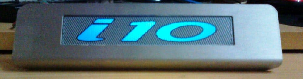
Back-light illumination In Dark:
Hi Swagatam
Thanks for the circuit I will build it and let you know how I get on
so again thanks for helping me out and getting back to me
regards
sparks
No problems Sparks,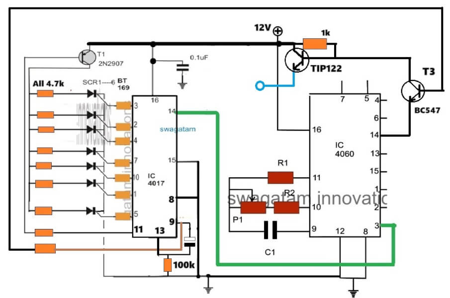
let me know if you face any problems with the circuit:
" rel="ugc">
Hi
swagatam
thank you for the reply and the explanation regarding the resistors connection to the anode of the scr and the change to the circuit
reqards
No problem, Sparks, let me know if you face any further problems.
We will continue the conversation under an LED chaser article, so please post them under the following article:
https://www.homemade-circuits.com/knight-rider-led-chaser-circuit-mains/
Hi really enjoy reading about various article/ circuits the latching 10 way chaser circuit can it be modified so that on the last count can all the led all flash at once then reset to complete the cycle I want to use this circuit for a sign so I hope you can help
reqards
Thanks for your kind feedback, yes that’s possible. Please show me the diagram link I will modify it accordingly…
hi swagatam
It’s the sequential led array light circuit that I am interested in and is it possible to modify this circuit so that at the end of the 4017 last cycle it would flash all the led say for about two to three seconds then reset the leds would be changed for maybe mosfets for switching lamps or more LEDs
thank you for your time
regards
Hi Sparks,
I can modify the following circuit as per your specifications, but the circuit might become slightly lengthy and complex.
Can you please tell me how many LEDs you need per channel, and the LED current spec?
https://www.homemade-circuits.com/sequential-bar-graph-turn-light/
hi swagatam
I was thinking I might use about 15 led per channel but only eight channel would be used thanks for getting back so quick
regards
sparks
Hi Sparks,
I tried it but its getting too much lengthy circuit, because the outputs of 4017 does not latch by itself, so we have to use external latching devices like SCRs for latching the LEDs, and because of this, flashing the LEDs at the end without breaking the latch is making the circuit more complex…
is it ok, if the circuit has many parts and stages?
Hi swangatam
thanks for replying I don’t mind what method are used( extra components etc ).as long as it can.be done
regards
sparks
Thank you sparks,
here’s the circuit you can try for illuminating 9 LED strings in sequence until all the 9 channels are illuminated and then flash the whole array for a few seconds and restart the process. Each LED string will need to be connected across the individual SCR ANODEs and the common terminal of TIP122 EMITTER. I hope it works as intended:
" rel="ugc">
Hi Swagatam
can you.tell me the purpose of the 4.7k resistors in series with the anode of each scr and the value of the capacitor connected to pin 9&13 for the 4017 please
reqards
Hi Sparks,
The 4.7k resistors ensure the SCRs remains latched even while the LEDs are flashing at the end of the sequence.
The value of that capacitor will need to be experimented, you can start with a 10uF and check the results. This capacitor decides how long the LEDs flash at the end of the sequence.
Also, please disconnect the emitter of the BC547 from pin#14 of the 4060, and instead connect it with pin#1 of the same IC.
very fine sir, i want to see this artcal by video please.
Can you please tell me where do we get the plastic lens?
ordinary plastic will not do, only acrylic plastics will work for this application, your nearest plastic dealer will know better.