This two tone siren circuit explained here gives out a continuously varying high amplitude sound. Since the supply voltage is not critical, it can be used in cars, motor cycles or at home. It can replace the ordinary call bell.
A dual one siren is an amplified alarm circuit designed to generate two different audio tones resembling an alarm sound operating with two alternating tone outputs.
Circuit Operation
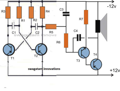
The circuit consists of two separate free running multivibrator and an oscillator.
A free running or astable multivibrator is one which has two quasi-stable states and the output of one stag is connected to the input of the other through a coupling capacitor.
Since both the states are quasi-stable, the output attained is continuously varying in nature i.e. high, low high low.
The output is in the form low pulses, the frequency of which depends on the base biasing resistor and the coupling capacitor.
When these resistances and condensers for both the stages are of different values, the output wave form is rectangular; this is because the time constant of the two quasi-stable states becomes different.
If this time constant of the two, states is made the same, the output obtained then is square wave. Two states of the multivibrator are made identical by the use of the same values of components.
The components used in this dual tone siren circuit result in a square wave output and the time constant selected is so as to give a fairly good rise and fall of the siren.
However, one may change the value of coupling capacitors to get any other desired time constant.
The second unit is an oscillator section. The condenser connected at the output is the feed back condenser. It determines the tone of the siren.
Higher the value of the condenser the lower is the pitch, for high pitch sound (generally used in siren) feed-back condenser ranging from 0.047 ufd to 0.1 mfd should be selected.
The speaker may be metallic case (horn type) or small paper cone. The metallic cone horn gives better results.
The transistor astable parts could be calculated with the following formula:
- T2 = OFF Period of transistor Q1 = ON Period of Transistor Q2 = 0.693 * R2 * C2
- T1 = OFF Period of transistor Q2 = ON Period of Transistor Q1 = 0.693 * R1 * C1

Parts List
- Transistors : BC177 2 Nos.
- BC 107 1No. T 1
- SK100 1No.
- Coudensers : 16 mfd 16 volts 1 No.
- 0.1 mfd 3 Nos.
- Resistances (1/4watt) 2.2 K 2 Nos.
- 22 K 2 Nos.
- 27 K 2 Nos.
- 10 ohm 1No.
- Speaker 8+16 ohm.
2 Tone Siren Using IC 7400
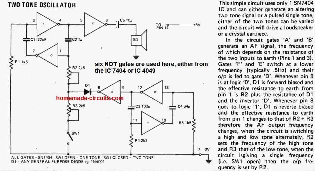
The next 2 tone siren circuit siren is built using two oscillators for generating the tones.
A third oscillator is incorporated to toggle its counterparts ON/OFF alternately, producing the required two tone sound effect.
You can try experimenting with the value of the capacitor for having different ranges of tones and change it as per your preferences.

Formula for Calculating the NAND gate Oscillator
Frequency (f) ≈ 1 / (2.1 * R * C)
Where:
- R is the resistance in ohms
- C is the capacitance in farads
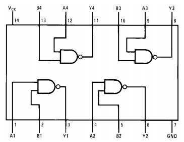
IC 7400 pinout diagram


Two Tone Alarm Circuit using NAND Gates
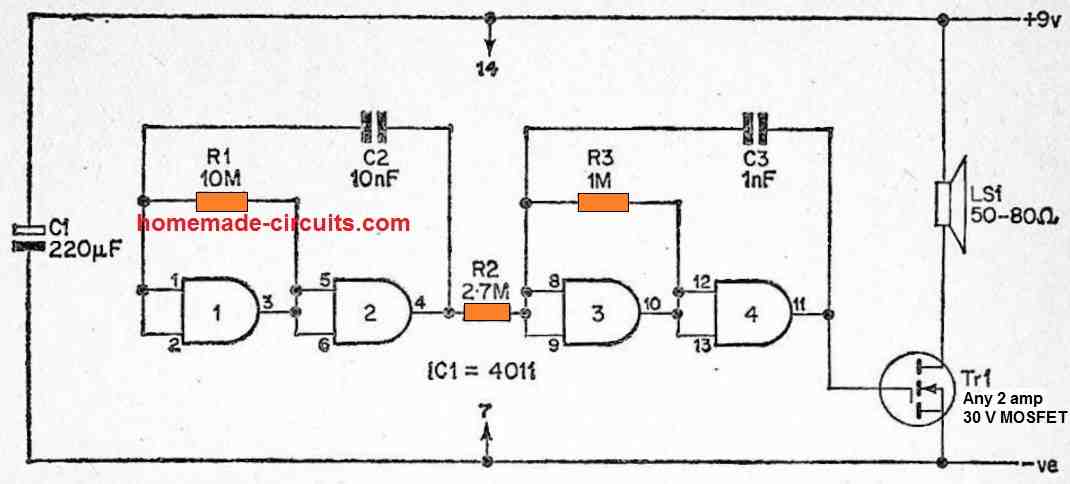
The frequency modulated alarm generator is yet another highly effective type of two tone alarm generator.
In this case, the frequency of the output tone is altered in a specific manner. By implementing a square wave modulating signal, for instance, the tone is altered between two different tones at a rate equivalent to the modulation oscillator's frequency.
When a triangle modulation signal is used, the output signal's tone is exponentially changed up and down with the operating frequency of the modulation oscillator.

However, R2 only weakly links the modulation astable's output to the tone generator astable's input, and the latter's operating frequency is switched up and down as the modulation oscillator's output shifts from one logic state to another.
As a result, the tone generator's frequency output is altered between roughly 500 Hertz and 1.2 kHz, and it simply does not work at its normal operational frequency.