In this article I have explained 10 simple automatic emergency light circuits using high bright LEDs. This circuit can be used during power failures and outdoors where any other source of power might be unavailable.
What's an Emergency Lamp
An emergency light is a circuit which automatically switches ON a battery operated lamp as soon as the mains AC input is unavailable or during mains power failure and outages.
It prevents the user from being into an inconvenient situation due to sudden darkness, and helps the user to get access to an instant make shift emergency illumination.
The discussed circuits uses LEDs instead of incandescent lamp, thus making the unit very power efficient and brighter with its light output.
Moreover, the circuit employs a very innovative concept especially devised by me which further enhances the economical feature of the unit.
Let’s learn the concept and the circuit more closely:
Warning: A few circuits I have explained below, without using transformer are not isolated from mains AC, and therefore are extremely dangerous to touch in the powered and open condition. You should be extremely careful while building and testing these circuits, and make sure to take the necessary safety precautions. The author cannot be held responsible for any mishap due to any negligence by the user.
Automatic Emergency Light Theory
As the name suggests, it is a system that automatically switches ON a lamp when regular AC supply fails, and switches it OFF when mains power returns.
An emergency light can be crucial in areas where power outage is frequent, as it can prevent the user from going through an inconvenient situation when suddenly mains power shuts down. It allows the user to continue with the ongoing task or access a better alternative such as switching ON a generator or an inverter, until mains power is restored..
1) Using a Single PNP Transistor

The concept: We know that LEDs require a certain fixed forward voltage drop to become illuminated and it is at this rating when the LED is at it’s best, that is voltages which is around its forward voltage drop facilitates the device to operate in the most efficient way.
As this voltage is increased, the LED starts drawing more current, rather dissipating extra current by getting heated up itself and also through the resistor which also gets heated up in the process of limiting the extra current.
If we could maintain a voltage around an LED near to its rated forward voltage, we could use it more efficiently.
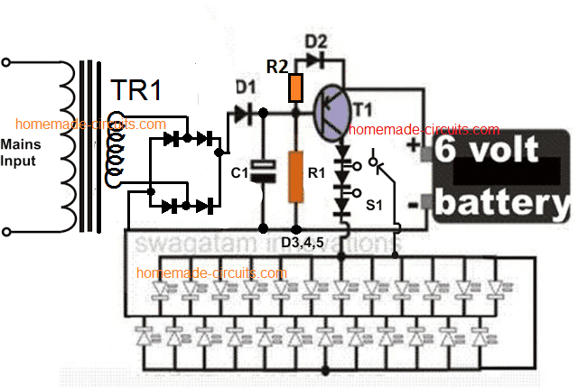
That’s exactly what I have tried to fix in the circuit. Since the battery used here is a 6 volt battery, means this source is a bit higher than the forward voltage of the LEDs used here, which amounts to 3.5 volts.
The extra 2.5 volts rise can cause considerable dissipation and loss of power through heat generation.
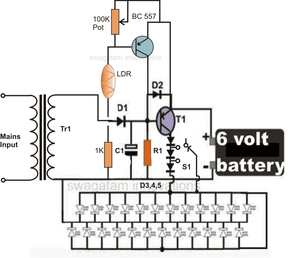
Therefore I employed a few diodes in series with the supply and made sure that initially when the battery is fully charged; three diodes are effectively switched so as to drop the excess 2.5 volts across the white LEDs (because each diode drop 0.6 volts across itself).
Now as the voltage of the battery drops, the diodes series are reduced to two and subsequently to one making sure only the desired amount of voltage reaches the LED bank.
In this way the proposed simple emergency lamp circuit is made highly efficient with its current consumption, and it provides backup for a much longer period of time than what it would do with ordinary connections
However, you can remove those diodes if you don't want to include them.
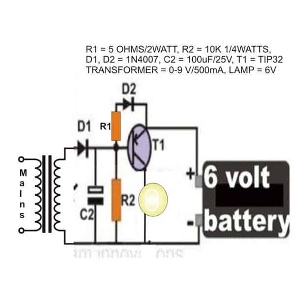
Circuit Diagram
How this white LED Emergency Light Circuit Works
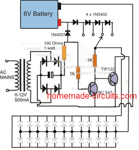
Referring to the circuit diagram, we see that the circuit is actually very easy to understand, let’s evaluate it with the following points:
The transformer, bridge and the capacitor forms a standard Power supply for the circuit. The circuit is basically made up of a single PNP transistor, which is used as a switch here.
We know that PNP devices are referenced to positive potentials and it acts like ground to them. So connecting a positive supply to the base of a PNP device would mean grounding of its base.
Here, as long as mains power is ON, the positive from the supply reaches the base of the transistor, keeping it switched off.
Therefore the voltage from the battery is not able to reach the LED bank, keeping it switched off. In the meantime the battery is charged by the power supply voltage and it’s charged through the system of trickle charging.
However, as soon as the mains power disrupts, the positive at the base of the transistor disappears and it gets forward biased through the 10K resistor.
The transistor switches ON, instantly illuminating the LEDs. Initially all the diodes are included in the voltage path, and are gradually bypassed one by one as the LED gets dimmer.
HAVE ANY DOUBTS? FEEL FREE TO COMMENT AND INTERACT.
Parts List
- R1 = 10K,
- R2 = 470 ohms
- C1 = 100uF/25V,
- Bridge diodes and D1, D2 = 1N4007,
- D3---D5 = 1N5408,
- T1 = BD140
- Tr1 = 0-6V, 500mA,
- LEDs = white, hi-efficiency, 5mm,
- S1 = switch with three changeover contacts. Using Transformerless power supply
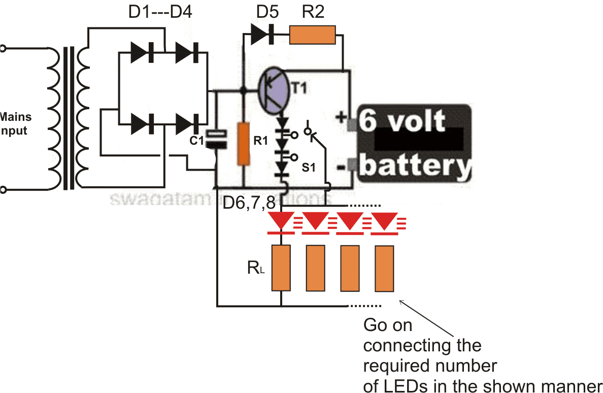
The design presented above can be also made using a transformerless supply as shown below:
Here I will elucidate how an emergency lamp can be build without a transformer using a some LEDs and a handful of ordinary components.
The main features of the proposed automatic transformerless emergency light circuit is though very identical to the earlier designs, the elimination of the transformer makes the design pretty handy.
Because now the circuit becomes very compact, low cost and easy to build.
However, the circuit being completely and directly linked with the AC mains is hugely dangerous to touch in an uncovered position, so it is obvious that the constructor implements all the due safety measures while making it.
Circuit Description
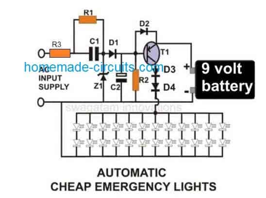
Coming back to the circuit idea, transistor T1 being an PNP transistor tends to remains in switched OFF condition as long as AC mains is present across its base emitter.
Actually here the transformer is replaced by the configuration consisting of C1, R1, Z1, D1 and C2.
The above parts constitute a nice little compact transformerless power supply, capable of keeping the transistor switched OFF during mains presence and also trickle charges the associated battery.
The transistor reverts to a biased condition with the help of R2 the moment AC power fails.
The battery power now passes through T1 and lights up the connected LEDs.
The circuit shows a 9 volts battery, however a 6 volt battery may also be incorporated, but then D3 and D4 will need to be completely removed from their positions and replaced by a wire link so that the battery power is able to flow directly through the transistor and the LEDs.
Automatic Emergency Light Circuit Diagram
Video Clip:
Parts List
- R1 = 1M,
- R2 = 10K,
- R3 = 50 ohm 1/2 watt,
- C1 = 1uF/400V PPC,
- C2 = 470uF/25V,
- D1, D2 = 1N4007,
- D3, D4 = 1N5402,
- Z1 = 12 V/ 1Watt,
- T1 =BD140,
- LEDs, White, High Efficiency, 5mm
PCB Layout for the above circuit (Track side view, Actual Size)

Pats List
- R1 = 1M
- R2 = 10 ohm 1 watt
- R3 = 1K
- R4 = 33 ohm 1 watt
- D1---D5 = 1N4007
- T1 = 8550
- C1 = 474/400V PPC
- C2 = 10uF/25V
- Z1 = 4.7V
- LEDs = 20ma/5mm
- MOV = any standard for 220V application
PNP BJT Current Flow
In a PNP transistor we see that current flows from the emitter to the collector when the transistor is in its "on" state. The base current which we call IB plays a crucial role in controlling how much current flows through the collector-emitter path.
Emitter Current (IE)
The current that comes out of the emitter is related to both the collector current and the base current. We can express this relationship with the formula:
IE = IC + IB
Where:
- IE is the emitter current.
- IC is the collector current.
- IB is the base current.
Collector Current (IC)
When we are in the active region the collector current is dependent on the base current through what we call the current gain (β) of the transistor. This can be written as:
IC = β * IB
Where:
- IC represents the collector current which is also the current flowing through any LED load we have connected.
- β is the current gain (also known as hFE) of the PNP transistor and it usually ranges from about 100 to 300.
- IB is again our base current.
Base Current (IB)
To figure out the base current we can use the input voltage along with the base-emitter voltage (VBE). The formula looks like this:
IB = (Vin - VBE) / RB
Where:
- Vin is the voltage we apply to the base.
- VBE is the base-emitter voltage which is typically around 0.7V when our transistor is turned on.
- RB is the base resistor that helps limit how much base current flows.
LED Load Current
Now if we assume that our LEDs are connected in the collector circuit we can relate the current through these LEDs to both the voltage drop across them and the collector-emitter voltage. The LED current can be expressed as:
ILED = (VCC - VCE) / RLED
Where:
- VCC is the supply voltage for our circuit.
- VCE is the collector-emitter voltage which should ideally be low when our transistor is fully on....typically around 0.2V or even less.
- RLED is a resistor that limits the current for our LEDs if we are using one in series.
For simplicitys sake if we assume that VCE ≈ 0V when our transistor is fully on then we can say that:
ILED ≈ VCC / RLED
Base-Emitter Voltage (VBE)
For our PNP transistor to turn on properly, we need to make sure that the base-emitter junction is forward-biased. The base-emitter voltage (VBE) for a conducting PNP transistor usually sits around 0.7V when it’s in active mode.
While this value can vary slightly depending on the specific transistor we're using, it’s generally close to that 0.7V mark.
Saturation of the PNP Transistor (V{CE(sat)})
When our PNP transistor is fully turned on or saturated, we notice that the collector-emitter voltage (VCE) drops down to a very low value, which we refer to as saturation voltage:
VCE(sat) ≈ 0.2V
This low voltage across the transistor means that most of our supply voltage gets dropped across whatever LED(s) and any current-limiting resistor we have in place.
2) Surge Protected Automatic Emergency Lamp
The following surge proof emergency lamp circuit employs 7 series diodes connected in forward biased condition across the supply line after the input capacitor. These 7 diodes drop around 4.9V, and thus produce a perfectly stabilized and surge protected output for charging the connected battery.
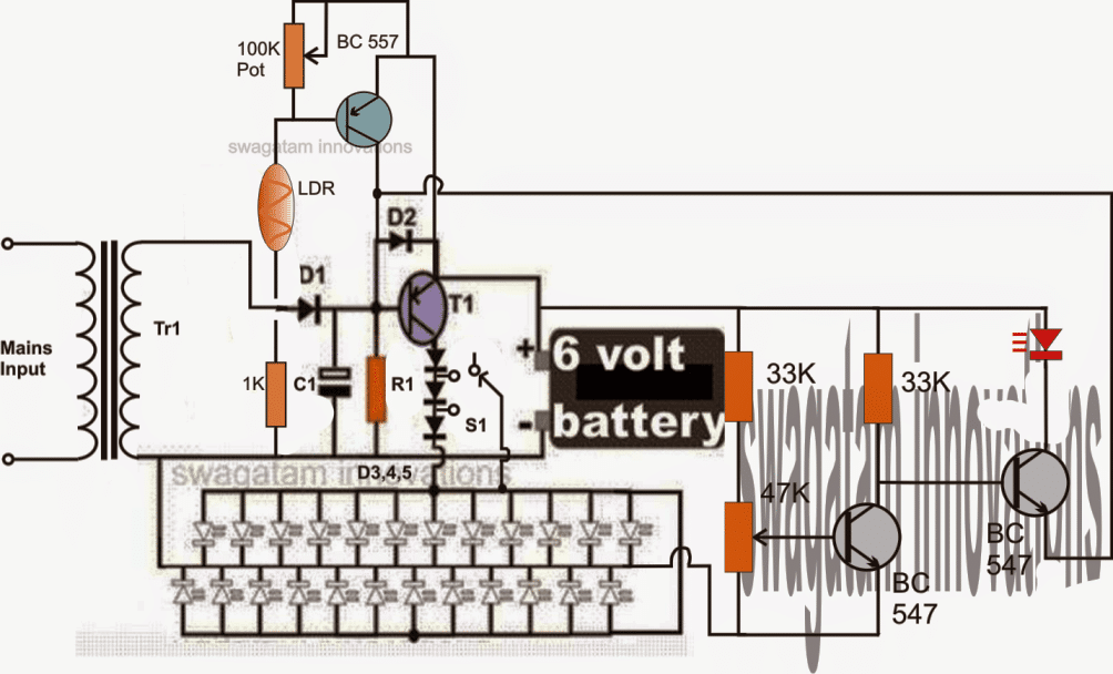
Emergency Lamp with Automatic Day Night LDR Activation
In response to the suggestion of one of our avid readers, the above automatic LED emergency light circuit has been modified and improved with a second transistor stage incorporating an LDR trigger system.
The stage renders the emergency light action ineffective during day time when ample ambient light is available, thus saving precious battery power by avoiding unnecessary switching of the unit.
Circuit modifications for operating 150 LEDs, requested by SATY:
Parts List for the 150 LED emergency light circuit
R1 = 220 Ohms, 1/2 watt
R2 = 100Ohms, 2 watts,
RL = All 22 Ohms, 1/4 watt,
C1 = 100uF/25V,
D1,2,3,4,6,7,8 = 1N5408,
D5 = 1N4007
T1 = AD149, TIP127, TIP2955, TIP32 or similar,
Transformer = 0-6V, 500mA
3) Automatic Emergency Lamp Circuit with Low Battery Cut-off
The following circuit shows how a low voltage cut off circuit can be included in the above design for preventing the battery from getting over discharged.
4) Power Supply Circuit with Emergency Light Application
The 4rth circuit shown below was requested by one of the readers, it is a power supply circuit which trickle charges a battery when AC mains is available, and also feeds the output with the required DC power via D1.
Now, the moment AC mains fails, the battery instantly backs up and the compensates the output failure with its power via D2.
When input Mains is present, the rectified DC passes through R1 and charges the battery with the desired output current, also, D1 transfers the transformer DC to the output for keeping the load switched on simultaneously.
D2 remains reverse biased and is not able to conduct because of higher positive potential produced at the cathode of D1.
However when mains AC fails, the cathode potential of D1 becomes lower and therefore D2 starts conducting and provides the battery DC back up instantly to the load without any interruptions.
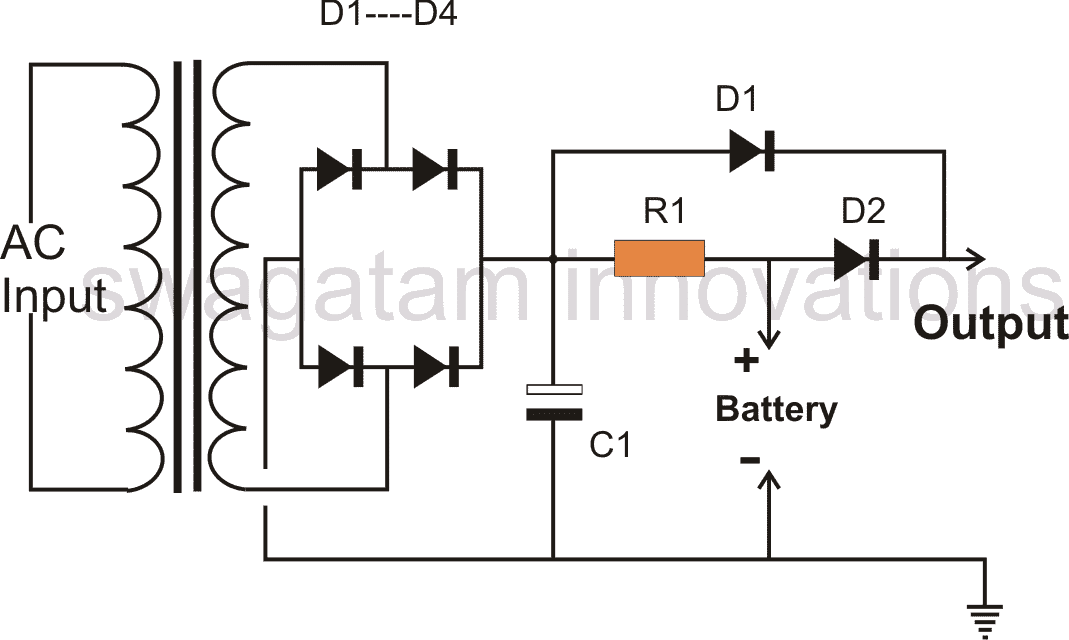
Parts List for an emergency light back up circuit
All Diodes = 1N5402 for battery up to 20 AH, 1N4007, two in parallel for 10-20 AH battery, and 1N4007 for below 10 AH.
R1 = Charging Volts - Battery volts / charging current
Transformer Current/Charging current = 1/10 * batt AH
C1 = 100uF/25
5) Using NPN transistors
The first circuit can be also built using NPN transistors, as shown here:
6) Emergency Lamp using Relay
This 6th simple LED relay changeover emergency light circuit using a battery back up which gets charged during mains presence and changes over to LED/battery mode as soon as mains fails. The idea was requested by one of the members of this blog.
Circuit Objectives and Requirements
The following discussion explains the application details for the proposed LED relay changeover emergency lamp circuit
I am trying to make very simple changeover circuit.. where I am using a 12-0-12 Transformer to charge a 12v Motorcycle battery via mains.
When the mains go off the battery will power a 10w LED. But, the problem is the relay is not switching off, when the mains goes down.
Any ideas. Want to keep it really simple.. 12VDC Relay / 2200uf-50v cap on Transformer.
My Response:
Hi, make sure that the relay coil is connected with the rectified DC from the 12-0-12 transformer. The relay contacts should be only wired with the battery and the LED.
Feedback:
Firstly Thanks for the Reply.
1. Yes the Relay Coil is connected with the Rectified DC.
2. If I connect the relay contacts to Battery / LED only, then how will the Battery get charged when Mains is ON?
If i am not missing anything..
The Design
The above circuit is self explanatory and shows the configuration for implementing a simple LED relay changeover emergency lamp circuit.
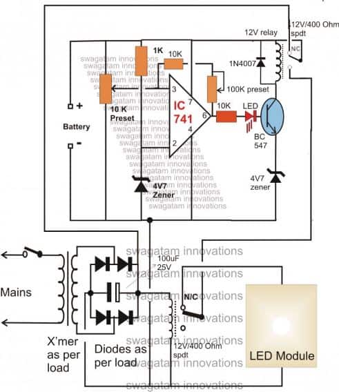
Using a Relay and without Transformer
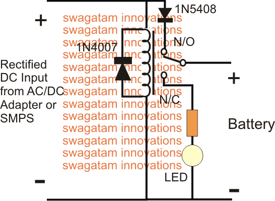
This is a new entry, and shows how a single relay can be used for making an emergency lamp with charger.
The relay can be any ordinary 400 ohm 12V relay.
While mains AC is available, the relay is energized using the rectified capacitive power supply, which connects the relay contacts with its N/O terminal. The battery now gets charged through this contact via the 100 ohm resistor. The 4V zener makes sure that the 3.7 Cell never reaches an over charged situation.
When mains AC fails, the relay deactivates, and its contact is pulled at its N/C terminals. The N/C terminals now connects the LEDs with the battery, illuminating it instantly via the 100 ohm resistor.
If you any specific questions, please ask using the comment box.
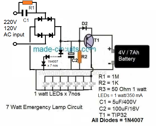
7) Simple Emergency Lamp Circuit using 1 Watt LEDs
Here I have explained a simple 1 watt led emergency lamp circuit using li-ion battery. The design was requested by one of the keen readers of this blog, Mr. Haroon Khurshid.
Technical Specifications
Can you help me design a circuit to charge a
nokia 3.7 volt battery by using regular nokia cellphone charger circuit and utilize that battery for lighting 1watt leds connected in parallel there should be light indicator and also automatic on of system in case of power failure kindly you consider my idea and design one
kind Regards,
Haroon khurshid
The Design
The requested 1 watt led emergency lamp circuit using li-ion battery may be easily built with the help of the below given schematic:
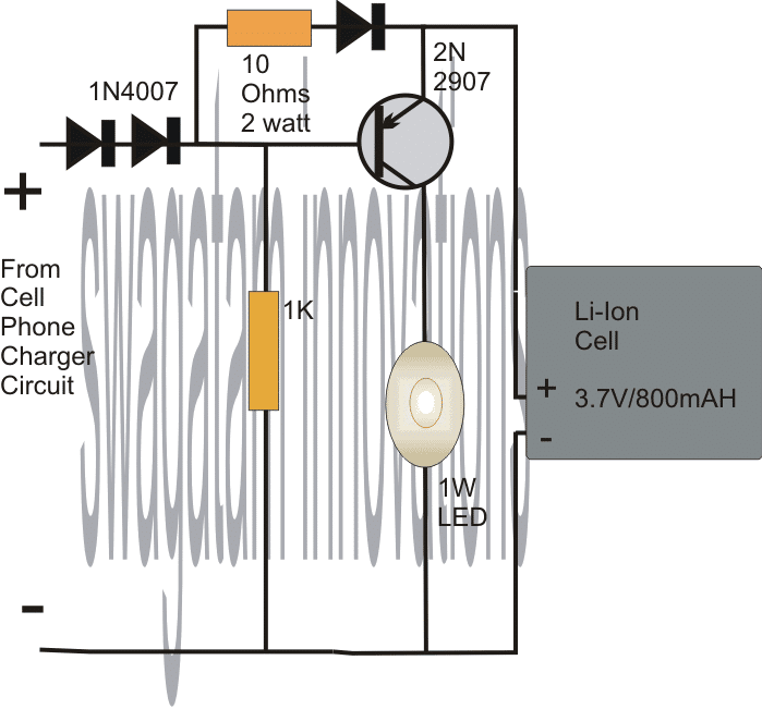
Adding a Current Control for the LED
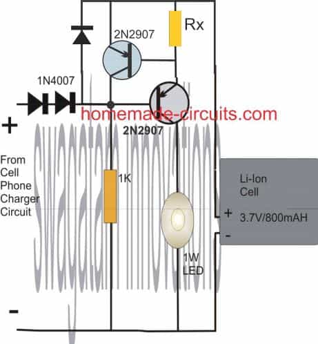
Rx = 0.7 / 0.3 = 2.3 ohm 1/4 watt
The voltage from the cell phone charger power supply is dropped to around 3.9V by adding diodes in the positive path of the supply. This should be confirmed with a DMM before connecting the cell.
The voltage should be limited to around 4V so that the cell is never allowed to cros the over charge limit.
Although the above voltage will not allow the cell to get charged fully and optimally, it will ensure the cell doesn't get damaged due to over charge.
The PNP transistor is held reversed biased as long as mains AC stays active, while the Li-Ion cell is charged gradually charged.
In case the mains AC fails, the transistor switches ON with the help of the 1K resistor and instantly illuminates the 1 watt LED connected across its collector and ground.
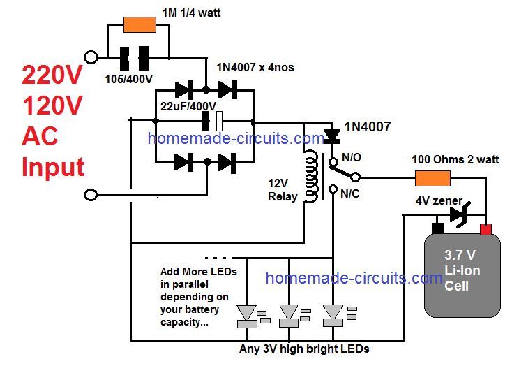
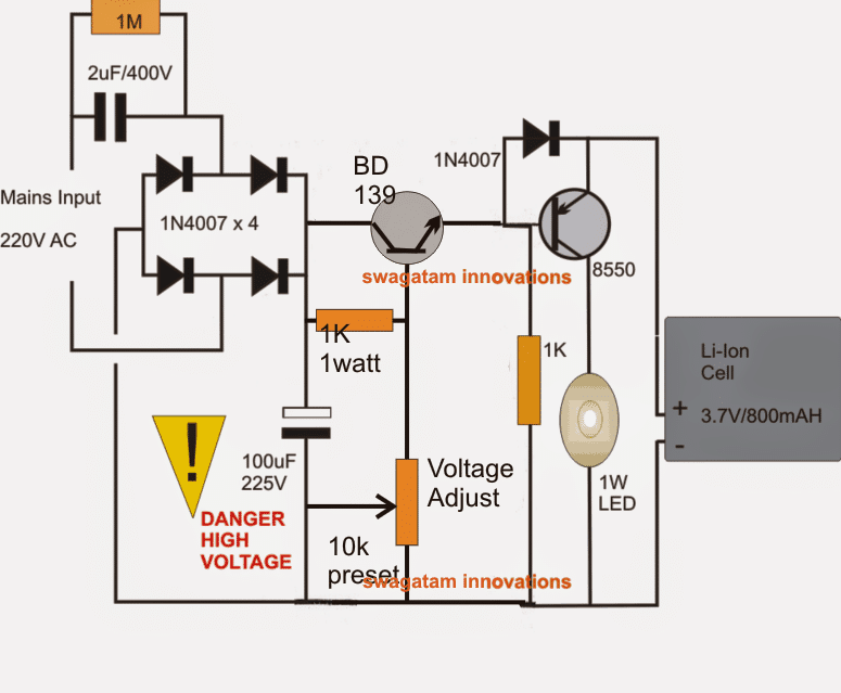
The above design can also be implemented using a transformerless power supply circuit. Let's the learn the complete design:
Before proceeding with the circuit details it should be noted that the following proposed design is not isolated from mains and therefore is extremely dangerous to touch, and it has not been verified practically. Build it only if you personally feel sure about the design.
Moving on, the given 1 watt LED emergency light circuit using Li-Ion cell looks quite a straightforward design. I have explained the functioning with the following points.
It's basically a regulated transformerless power supply circuit which can also be used as a 1 watt LED driver circuit.
The present design perhaps becomes very reliable owing to the fact that the dangers normally associated with transformerless power supplies are effectively tackled here.
The 2uF capacitor along with the 4 in4007 diodes form a standard mains operated capacitive power supply stage.
Adding an Emitter Follower for Voltage Regulation
The preceding stage which consists of an emitter follower stage and the associated passive parts form a standard variable zener diode.
The main function of this emitter follower network is to restrict the available voltage to precise levels set by the preset.
Here it should be set at around 4.5V, which becomes the charging voltage for the Li-ion cell. The final voltage that reaches the cell is around 3.9V due to the presence of the series diode 1N4007.
The transistor 8550 acts like a switch which activates only in the absence of power through the capacitive stage, meaning when AC mains is not present.
During the presence of mains power the transistor is held reverse biased due to the direct positive from the bridge network to the base of the transistor.
Since the charging voltage is restricted at 3.9V keeps the battery just under the full charge limit and therefore the danger of over charging it is never reached.
In the absence of mains power, the transistor conducts and connects the cell voltage with the attached 1 watt LED across the collector and ground of the transistor, the 1watt LED illuminates brightly....when mains power restores, the LED is switched OFF immediately.
If you have further doubts or queries regarding the above 1 watt led emergency lamp circuit using li-ion battery, feel free to post them through your comments.
8) Automatic 10 watt to 1000 watt LED Emergency Light Circuit
The following 8th concept explains a very simple yet an outstanding automatic 10 watt to 1000 watt emergency lamp circuit. The circuit also includes an automatic over voltage and low voltage battery shut off feature.
The entire circuit functioning may be understood with the following points:
Circuit Operation
Referring the below given circuit diagram, the transformer, bridge and the associated 100uF/25V capacitor forms a standard step down AC to DC power supply circuit.
The bottom SPDT relay is directly connected with the above power supply output such that it remains activated when mains is connected with the circuit.
In the above situation, the N/O contacts of the relay stay connected which keeps the LED shut OFF (since it's connected with the N/C of the relay).
This takes care of the LED switching, making sure than the LEDs are switched ON only in the absence of mains power.
However, the positive from the battery is not directly connected with the LED module, rather it comes via another relay N/O contacts (the upper relay).
This relay is integrated with a high/low voltage sensor circuit stationed for detecting the battery voltage conditions.
Supposing the battery is in a discharged condition, switching ON the mains keeps the relay deactivated so that the the rectified DC can reach the battery via the upper relay N/C contacts initiating the charging process of the connected battery.
When the battery voltages reaches the "full charge" potential, as per the setting of the 10 K preset, the relay trips and joins with the battery through its N/O contacts.
Now in the above situation if the mains fails, the LED module is able to get powered via the above relay and the lower relay N/O contacts and get illuminated.
Since relays are used, the power handling capacity becomes sufficiently high. The circuit is thus able to support in excess of 1000 watts of power (lamp), provided the relay contacts are appropriately rated for the preferred load.
The finalized circuit with an added feature can be seen below:
The circuit was drawn by Mr. Sriram kp, for details please go through the comment discussion between Mr Sriram and me.
9) Emergency Light Circuit Using a Flashlight Bulb
In this 9 idea I have explained the making of a simple emergency lamp using a 3V/6V flashlight bulb.
Though it's the world LEDs today, an ordinary flashlight bulb can also be considered a useful light emitting candidate especially because it's much to configure than an LED.
The shown circuit diagram is quite simple to understand, a PNP transistor is used as the primary switching device.
A straight forward power supply provides the power to the circuit when mains is available.
Circuit Operation
As long as power is present, the transistor T1 remains positively biased and therefore remains switched OFF.
This inhibits battery power from entering the bulb and keeps it switched OFF.
The mains power is also utilized for charging the involved battery via the diode D2 and the current limiting resistor R1.
However, the moment AC mains fails, T1 is instantly forward biased, it conducts and allows the battery power to pass through it, which ultimately turns ON the bulb and the emergency light.
The entire unit may be adjusted inside a standard AC/DC adapter box and plugged IN directly in to an existing socket.
The bulb should be kept protruding outside the box so that the illumination reaches the external surrounding amply.
Parts List
- R1 = 470 Ohms,
- R2 = 1K,
- C2 = 100uF/25V,
- Bulb = Small Flashlight Bulb,
- Battery = 6V, Rechargeable Type,
- Transformer = 0-9V, 500 mA
The Design and Schematic
10) 40 Watt LED Emergency Tubelight Circuit
The 10th awesome design talks about a simple yet effective 40 watt LED emergency tube light circuit which can be installed at home for acquiring uninterruptible illumination at the same time saving a lot of electricity and money.
Introduction
You might have read one of my earlier articles which explained a 40 watt LED street light system. The power saving concept is pretty much the same, through a PWM circuit, however the alignment of the LEDs has been laid in a completely different manner here.
As the name suggest the present idea is of an LED tube light and therefore the LEds have been configured in a straight horizontal pattern for better and efficient light distribution.
The circuit also features an optional emergency battery back up system which may be employed for getting an uninterruptible illumination from the LEDs even during the absence of normal mains AC.
Due to the PWM circuit the acquired backup can extend up to more than 25 hours on every single recharge of the battery (rated at 12V/25AH).
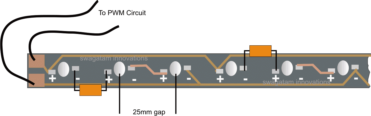
The PCB would be strictly needed for assembling the LEDs. The PCB must be an aluminum-back type. The track layout is shown in the below given picture.
As can be seen the LEDs are spaced at a distance of about 2.5 cm or 25mm from each other for enhancing maximum and optimal distribution of light.
Either the LEDs may be laid over a single row or over a couple of rows.
A single row pattern is shown in the below given layout, due to lack of space only two series/parallel connection has been accommodated, the pattern is continued further on the right side of the PCB so that all the 40 LEDs become included.
Normally the proposed 40 watt LED tube light circuit, or in other words the PWM circuit may be powered through any standard 12V/3amp SMPS unit for the sake of compactness and decent looks.
After assembling the above board, the output wires should be connected to the below shown PWM circuit, across the transistor collector and positive.
The supply voltage should be provided from any standard SMPS adapter as mentioned in the above section of the article.
The LED trip will instantly light up illuminating the premise with flood light brightness.
The illumination may be assumed to be equivalent to a 40 watt FTL with power consumption of less than 12 watts, that's a lot of power saved.
Emergency Battery Operation
If an emergency backup is preferred for the above circuit, it may be simply done by adding the following circuit.
Let's try to understand the design in more details:
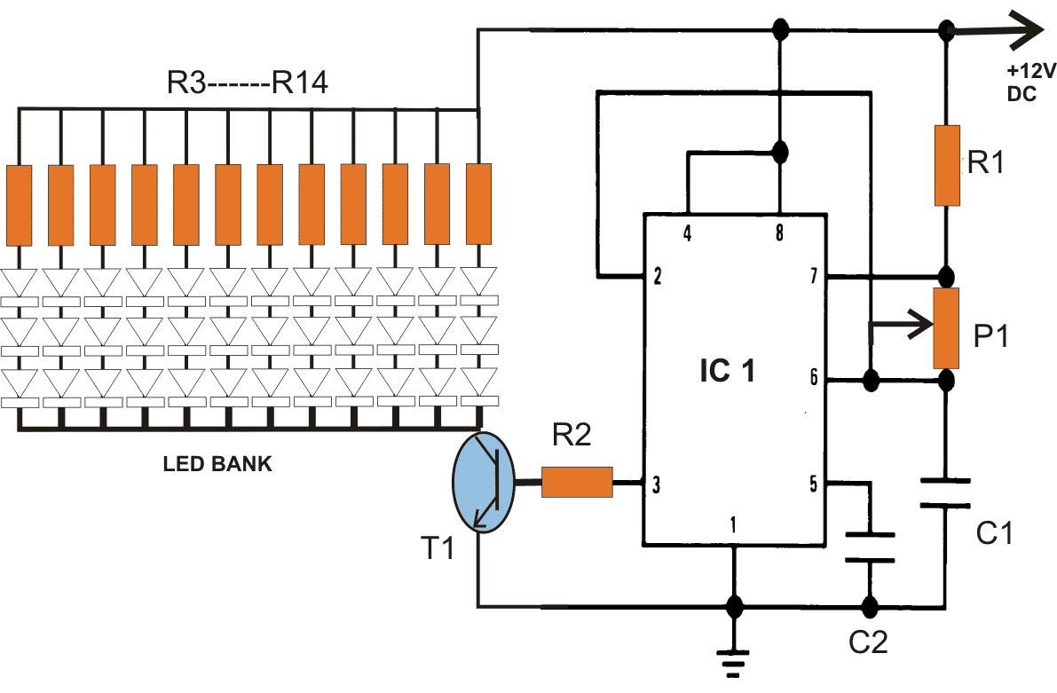
The circuit shown above is the PWM controlled 40 watt LED lamp circuit, the circuit has been elaborately explained in this 40 watt street light circuit article. You can refer it for knowing more about its circuit functioning.
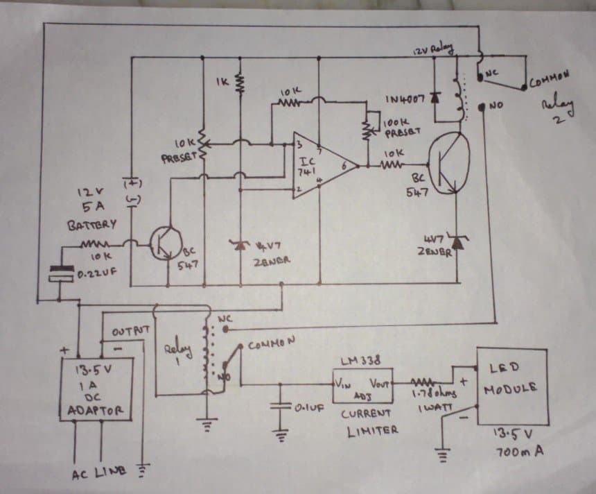
Automatic Battery Charger Circuit
The next figure shown below is an automatic under voltage and over voltage battery charger circuit with automatic relay changeovers. The whole functioning may be understood with the following points:
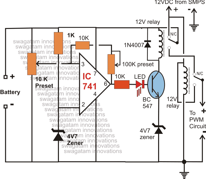
The IC 741 has been configured as a low/high battery voltage sensor and it activates the adjoining relay connected to the transistor BC547 appropriately.
Assume the mains to be present and the battery to be partially discharged. The voltage from the AC/DC SMPS reaches the battery through the N/C contacts of the upper relay which remains in an deactivated position because of the battery voltage which may be below the full charge threshold level, let's assume the full charge level to be 14.3V (set by the 10K preset).
Since the lower relay coil is connected to the SMPS voltage, stays activated such that the SMPS supply reaches the PWM 40 watt LED driver via the N/O contacts of the lower relay.
Thus the LEDs remains switched ON by using the DC from the mains operated SMPS adapter, also the battery continues to get charged as explained above.
Once the battery gets fully charged, the output of the IC741 goes high, activating the relay driver stage, the upper relay switches and instantly connects the battery with the N/C of the lower relay, positioning the battery in the standby condition.
However until AC mains is present, the lower relay is unable to deactivate and therefore the above voltage from the charged battery is not able to reach the LED board.
Now if suppose AC mains fails, the lower relay contact shifts to the N/C point, instantly connects the supply from the battery to the PWM LED circuit, illuminating the 40 watt LEDs brightly.
The LEDs consume battery power until either the battery falls below the low voltage threshold or mains power is restored.
The low battery threshold setting is done by adjusting the feedback preset 100K across the pin3 and pin6 of the IC741.
Over to You
So friends these were the 10 simple automatic emergency light circuits, for your building pleasure! If you any suggestions or improvements for the mentioned circuits please tell us using the comment box below.
Hello
thank you for nicely explained circuits of emergency lamps. I am newbie in the area and still learning and sorry for stupid question. But can you please explain if there is no risk of over charging battery in case long plug in to transformer? Can you please describe circuit that protects battery from overcharge? Thank you best regards marek
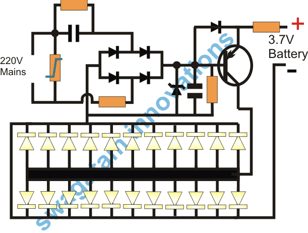
Hi, you are right, there could be a slight risk of overcharging the battery. In that case you can either decrease the input current supply to a nominal value, or do the same using a limiting resistor, in order to provide only a trickle charging for the battery. Another option is to restrict the charging voltage to the battery so that it is slightly lower than the full charge spec of the battery, through a voltage regulator…Below is a good example of a regulated supply using 7nos of 1N4007 series diodes. It restricts the voltage to the battery to around 4V, so that the battery never reaches is extreme full charging level. You can also use a combination of zener diodes to precisely set the charging voltage for the battery so that it a shade lower than the battery’s extreme full charge level.
" rel="ugc">
Thank you for response
Kr marek
dear Swagatam
Regarding the circuit “2) Surge Protected Automatic Emergency Lamp” let me know the connection of R3 ?in circuit cant see the R3 anywere,moreover the series 4007x7now diode polarity is also like that?
Thank you.
Hi Dr.Sison,
I forgot to show R3 in the design, this resistor can be anywhere in series with the input AC supply. However 50 ohms looks too large, instead you an use a 5 ohm resistor, even better if you replace it with a 5 ohm NTC thermistor.
Yes, the 1N4007 direction is the same as indicated in the diagram…
Dear Master,
First of all, thank you very much for your response, it was really explanatory, otherwise I could have made a mistake. I will complete the project in a few days. I think it is the best project I have found in my research. If there is a problem with anything, I will response it with you again, thank you, respectfully
You are welcome Metin,
I wish you all the best.
Let me know if you have any further questions.
Hello Swatagam, My question will be about project no:6 second scheme (without transfomer)
First of all, thank you very much for your valuable work.The side where the cathode ends of the LEDs are connected to the relay coil is also connected to one of the ac inputs. Sorry, there is a broken line in picture, I couldn’t fully understand it from the image, I would be very happy if you could help. Yours truly
Thank you Metin,
The broken line indicates, that particular line is not connected with the line which is crossing it.
So, the line which shows a break is connected only with the bridge rectifier negative, relay coil and the LED cathodes.
This line is NOT connected with the AC line which is crossing between the broken area.
I hope you got it, if not please let me know.
Sir,namaskaar mere paas 10mm led straw hat type 10 ki sankhya mein hai aur usse series mein chalane ke liye ek transformer less circuit bataye ismein kitne value ka x rated capacitor lagaye kripya bataye.
Hi Ashu, You can try the following circuit. Please replace the 12V zener diode with a 10 x 3 = 30V 2 watt zener diode.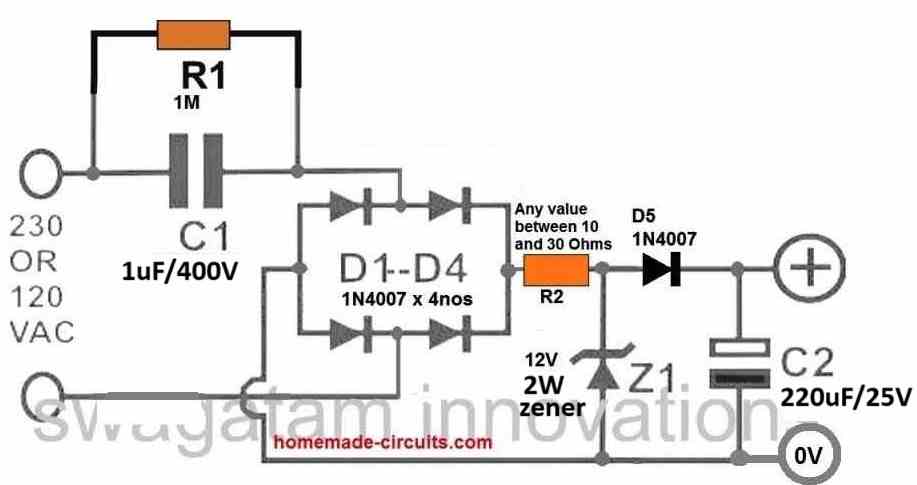
" rel="ugc">
Remember, this circuit is not isolated from mains 220V A and therefore is extremely dangerous to touch in an uncovered and powered ON condition.
Sir, saadar namaskaar mujhe koi zener nhi mil rha hai toh kya main iski jagah 220k resistor use kar sakte Hain agar haa toh iski value kis formula se nikale
Ashu, the 30 V zener diode is very important, a 220k resistor will not work.
If you cannot get one 30V zener, you can replace it with 3 or 4 series zener diodes.
For example you can put 3nos of 10V zener diodes in series, or 6nos of 5V zener diodes in series and so on.
Of course the requests never stop! I want my emergency light to also function as a darkness light ie in my corridor the light will turn on if a person passes from there even if the mains are still operating. So it will function in two modes: 1) emergency light when mains goes off AND it is dark, 2) motion detection light when it is dark. Thank you for beautiful work and circuits.
No problem….I will try to update the requested circuit in a new post soon…and let you know.
Please check out the following article:
https://www.homemade-circuits.com/darkness-activated-pir-lamp-circuit/
Thank you very much. I will try it.
Sure, no problem!
Thanks for your blog and all the circuits.
I wonder If you can help identify an IC on an Emergency light circuit that I have. It is similar to some of your 10 circuits, but has an IR sensor for remote control.
I reverse engineered the circuit and it is attached here.
https://drive.google.com/file/d/1A8zue9TtOUQ3scGncyNz1eC8h0eeFrYq/view?usp=sharing
Unfortunately the there is no visible marking on the IC. Please excuse the untidy circuit as I am just a beginner in electronics.
The link you have provided is not opening because you did not toggle the sharing mode, it seems. Please send it again with sharing mode ON.
Updated circuit:
https://drive.google.com/file/d/1zIRBKX2c0bK1o8z0nABnfEBrYng8LgJj/view?usp=sharing
Sorry, I tried my best, but I cannot remember any IC with that pinout configuration. It looks like a Chinese IC.
sir, gud ngt. kya hum no.9 circuit mein 9v,500 ma transformer ki jagah transformer less circuit use kar sakte hain
Yes you can use transformerless power supply in the 9th circuit, as shown below: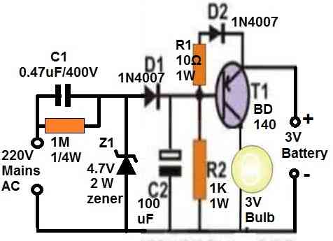
" rel="ugc">
But be careful, the circuit is not isolated from mains 220V AC.
sir, namaskaar kya hum ek 3v torch bulb ko capacitor ke saath series mein 220v ac per chala sakte hain kripya bataein
Hi Atul,
yes that is possible, you can light up a 3V flashlight bulb through a capacitor.
May I request more information on the subject? All of your articles are extremely useful to me. Thank you!
Needing some help with a circuit layout. I’m sending in 12v/5A (converting from 120v that I want to monitor). When the main power source loses power I’m switching over to 12v/9aH battery powering 20wLED. I want the led light to last as long as it can, so I need to put a float charger on a separate circuit to keep the battery charged during prolonged useage. I have tried another emergency light boards but after a period of time on battery they quit working even thought the battery is still charged. I’m shorting something out. Thanks!
The float charger can work only when mains AC input is available. The LED will last only for a period determined by the battery Ah rating and its charge level. If your emergency light board is not working despite the battery being fully charged then the LEDs might have gone faulty or maybe the controller is malfunctioning
Please I’m doing this as my final year project in the university, I want to do the design using 12v 3watts DC LED bulb. Will it work if I use two 3.7v li-ion batteries in series
A 12V LED will light up with lower brightness at 8V using two 3.7V cells in series.
Hi Swagatam,
I understand completely. I am sending you the basic schematic of a QX 5252F for your information. It is a four pin Solar Garden Light IC. The basic operation is the solar cell puts voltage into pin 1 when the sunlight shines on the solar cell. When pin one receives voltage, it turns off the output to the battery at pin 2. The IC has a diode to prevent the battery voltage from back flowing. The battery then provides voltage to the LED using the inductor and pin 4 to boost the voltage to 3+ volts. My question to you is, will the battery act similar to a capacitor and draw the voltage/current until it is full or near full which will keep the voltage/current from reaching the transistor base, so the transistor remains on until the battery gets full or near fully charged. Thanks
Hi Norman,
Yes the battery will behave like a capacitor and pull the required power for the charging process.
If you are using a PNP transistor, it will remain switched OFF as long as the battery voltage is above +0.7 V. If you want the transistor to switch OFF only at the full battery level, then you may have connect a zener diode in series with the base having a value equal to the full charge level of the battery.
Make sure to have a resistor across the base/ground of the transistor, otherwise it will never conduct. The battery (+) must be directly linked with the base of the PNP, not through a resistor.
Hi Swagatam,
I am trying to build a power failure emergency light using a single 1.2v rechargeable NIMH battery. I am trying to use the solar garden chip QX5252F so I can use one battery. The chip will also turn off the led when the unit is plugged into 120vac, the same as it does when a solar panel receives sunlight. I am also trying to provide overcharge protection as the unit will be plugged into 120vac all the time. I am using a small buck converter as power supply that reduces the 120vac to 5vdc. I am using an inline 2.4v zener and a voltage divider to reduce the power to the 1.2v battery. The idea is to deactivate the reed relay when the 1.2v battery gets fully charged. I am packaging all of this in a small plastic enclosure with US plug prongs. The schematic is attached. Your thoughts , please. I will also post my question on your site under an appropiate section.
Hi Norman, I saw your email, but since I have never used the IC QX5252F, I have no idea about it, and therefore it will be difficult for me to provide any useful suggestions.
Thank you very much sir
My name is Satty.
I need a help I have a circuit (emergency light circuit) I am not able to attach the circuit diagram since here no attachment is given, if so pls share your email i will attach the pic of that circuit, so that you can go through that and help me my need.
in this circuit it used the transformer less circuit which has 155micro fraud /400v and D965 transister is used to switching and 4v battery is used. in this i have changed the battery to lithium ion battery which is 3.7v around 3000mAH. here i need the battery low and full cutoff circuit which need to be added to the circuit.
Thanks and Regards
Satty
Hi, you can upload the images to any online free image hosting site and provide the uploaded link to me here, I’ll check them out and try to solve it for you!
Or you can also upload it to your Google drive, and send the link in the “sharing” mode.
" rel="ugc">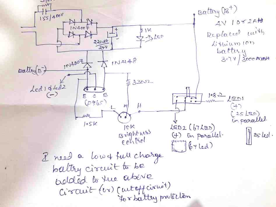
I have share the circuit. Please check and let me know your thoughts.
Thanks and Regards
Satty
Low cut off will make the circuit very complex, only high cut off can be added
can you please share your email id to give share to google drive and give the link
Satty
email is not required, there’s an option in google drive through which allows you to create a link that can be shared with anybody you want. Click the share button and create the link in the sharing mode.
i think you have the circuit. full charge and cut off circuit needed in the above circuit or basically battery to be protected even if you charge more time. That is the motive. please work and let me know your thoughts.
Thanks and Regards
Satty
any update
I can provide the battery charger separately but I can’t integrate in your circuit
ok, but is it so complicated my circuit. However please try, meantime you can share the circuit.
There are switches wired in your circuit which are confusing. You can try the following charger circuit:
The ZX zener value = full charge battery value + 0.6V
The ZY zener value = low battery value
The +DC input is the charging input, and the DC OUT goes to the load or the lamp.
The lower NPN transistor can be BC547
Hi,
Thank you for the circuit. Can you use D965 transistor since it has collector current 3A I can use more LED’s in this. Please check the your circuit and change with D965 transistor and give the circuit for full charge cut off circuit.
Thanks and Regards
Satty
LED will be controlled by the right side PNP transistor. You can use a TIP32C for the right side transistor. D965 is NPN transistor.
Hi, ok i will TIP32C.
ZY what value zener i have to use if i use 3.7v lithium battery.
Zx if my battery voltage is 3.7 then 3.7+0,6=4.3v then i have to use 4.2v zener is that right and what watt if any.
Thanks and Regards
Satty
The full charge level of a 3.7 V Li-Ion battery will be 4.2V, therefore the value of RX will be 4.2 + 0.6 = 4.8 V zener. After setting up the RX zener, connect the input voltage and measure the emitter voltage of TIP32, without any battery at the battery points. If you find it to be 4.2V then your RX is correctly set.
RY value can be a 3.7 V zener diode
Hi,
Thank you for your help.
i can use my tranformerless circuit to your DC input circuit right.
Do we need heat sink for TIP32. TIP32 and TIP32c are same or different?
For zener 1/4 watt is enough or not?
Thanks and Regards
Satty
Hi, if your transformerless power supply is well protected from surge current or is a low current type then it can be used otherwise it may not be safe for the transistors.
TIP32 will need a big heatsink if it used with a 3 amp load. TIP32 can be type all will work for the specified application.
1/4 watt zener will work…
Hi,
Thank you for your reply.
I need indicator also green and red for high and low can you put that in the above circuit and send me please.
Thanks and Regards
Satty
Hi, LED is not possible in this circuit because there’s no proper place for it. It is possible only in opamp circuits
Hi ,
Thank you for your help.
Can you please give same circuit for NPN transistor, it will helpful for me to replace if the circuit has NPN trasistor because i have more emergency light to convert to 3.7 voltage battery. Hope you understand take your time and sorry to bother you again.
Thanks and regards
Satty
Hi, sorry, NPN cannot be replaced with the shown PNP., because the circuit will then become messy and complex. PNP is perfectly suited in the given position, and I think PNP transistors are easily available in the market.
Hi,
Thank you for your help. you design for NPN and give me later since due to lock down we can’t go to the market to get the components, due to that i can have another additional circuit so that what ever components with me can be built, this is reason i asked for safer side i have npn and pnp circuit to learn more and ask doubts if any and where ever if is required i can implement either or circuit. Sorry for the trouble. I am so eager to learn in this to design so need your help more and more. Last time you designed for me one circuit 150 led and it is working fine. Thank you so much for you help again and again.
Thanks and regards
Satty
OK, thanks, if it’s possible I will try to design the circuit with all NPN transistors…..
Hi,
Thank you so much. You take your own time and give me the circuit.
It will be helpful for me to learn and to implement.
With Regards
Satty
Hi, you can try the following idea:
Hope this works!
Hi,
Thank you so much i will try this.
I have attached the transformerless circuit with this, please check and let me know if you need to change or modify.
the link is given below:
https://drive.google.com/file/d/1G6Y95afVXHZVCcM4TKCzJUGTBsAqU0Yi/view?usp=sharing
Thanks and Regards
Satty
The link is not opening, it is not in the shared mode!
Hi,
Please try this link
 " alt="transformerless rectifier" />
Thanks and Regards
Satty
The 155uF will burn everything on its way when power is switched ON…
Hi,
105uf is not available so 155uf is replaced.
I am using this transformerless circuit with 60 LEDs. with D945 transistor which works fine. only the battery is gone so i changed to 3.7 lithium battery to the above circuit.
However you can give me the transformerless circuit which suits for our NPN and PNP circuit which you have given to me.
Thanks and regards
Satty
Hi,
OK, so it’s number is 155 = 1500000pF = 1500 nF = 1.5 uF….It is not a 155uF.
Still, even a 1.5uF can also blow the transistors, there’s no way to stop this unless a zener diode and an NTC is used after the bridge.
If you are confident the circuit is alright then you can go ahead with the shown circuit.
Hi,
Thank you for your help. Yes you are right i might be confused with the number.
I have given the link for that pics. please check and let me know how to call this type of capacitor.
the number us return in that is 155J/400v.
However if you feel that this is not correct you can give me the transformerless circuit for our NPN / PNP circuit.
Thanks and Regards
Satty
Hi, capacitors are named depending on their material and type. The 155j/400V is normally a PPC high voltage type capacitor.
You can use your transformerless power supply for the intended purpose, just connect a zener diode after the bridge rectifier whose voltage value should be slightly higher than the maximum battery voltage. The zener must be rated at 5 watts. Also connect an NTC thermistor in series with the 155/400 capacitor
sorry link is not shared in the previous comment.
 " alt="155 400V PPC capacitor image" />
Thanks and Regards
Satty
OK thank you!
Hi,
Thank you, it is called PPC capacitor ok, is it 5watt zener to be connected?.
What is NTC thermistor and how it looks?
Can you give your transformerless circuit for this? what components are in your circuit, if you have please share so that i will learn.
Thank you for your help.
With Regards
Satty
Hi,
You can try the concept explained in the following article:
https://www.homemade-circuits.com/using-ntc-resistor-as-surge-suppressor/
Make sure to add a 5 watt zener diode after the bridge rectifier, and add a 10 ohm 2 watt resistor in series with the NTC
In the second part of circuit 6, Using a Relay Without a Transformer, can I use 3 x 18650 batteries and replace the zener for a 4.2 volt one? I would like to connect this to an array of 30 LEDs.
Yes you can but at a reduced current the batteries may take over 24 hours to get charged optimally.
I want to make an emergency for longer hour. So i am thinking to to make a switchable function where i want to use 5w led. For first spst it lights 1. 5w led for both spst it lights two 5w leds in parallel. So low light for normal situation and two lights for particular purpose. Can i use you no. 8 circuit??
And 2nd question is can i use 3S 18650 lipo cell pack of 8700mah instead sealed battery??
You can use the 8th relay circuit for your application. You can use lipo cell pack, just make sure that the charging voltage is regulated and marginally below the full charge level of the battery, and current should be 20 or 30% of the battery Ah value. The zener and the resistor near the battery will not work for your application. You will have to employ an appropriate voltage current regulator after the bridge rectifier
Hey, I am new to circuit designing. And sorry for all the trouble. I will be trying to make 4 no circuit and I don’t understand all the things. What I understand is given in the picture. Please tell me if I am correct or wrong? and I don’t get what transformer should I be using and what resistor should I be using. I know I will make a lot of mistakes and that’s okay with me. Help me if you have the time. Thanks in advance.
image link(you can comment on it)
https://drive.google.com/file/d/1sx83DGINoDactd6Kk4HlJms_SsQzX_A6/view?usp=sharing
Hi, The values of the parts are given below:
R1 = Voltage across C1 – 11.1 / 8 amps
All diodes must be 6A4 diodes.
Transformer should be 0-9, 8 amps
I hope you already have a voltage and current control for the LEDs
Hi Swagtam, i created the circuit as per ur 1st diagram using a single transistor. Here i use S8550 pnp transister and a resistor r2 of 470ohm with base which connected with ground. And a single diode d2 of 4007 only use. And i use 42 white led. Now the problem is the led are drawing 380 mA. But as per calculation the led should draw 840mA (42led*20mA) to run efficiency. Then what resistor to use. If i use 1k then current draw will be 280ohm. Pls help me
Hi chandrashekhar, the formula is:
R = (Battery V – LED fwd V) x hfe / LED current
this will give you the base resistor for the transistor. But 8550 will not handle 840 mA unless a perfect cooling is employed. Try TIP127 instead.
Hi Swagatan, thank you for the good work. I want to convert the 6th circuit with or without relay to keep a stand by back-up lithium 3,7v fully charged for enabling an uninterrupted operation of the LEDs lit even during mains failures. I want the transformerless power supply circuit to trickle charge the 3.7V battery when AC mains is available, and also to feed the output with the required DC. What components do i have to take out or add. Thanks
Thank you Emma, you can use the shown circuit as it is without any change. Just make sure to have a precise 4 V ot 4.1V across the terminals which is supposed to charge the battery. This could be done by a 4.1V zener or a transistor emitter follower, or any other suitable method.
Thanks for the prompt reply. I am just a bit confused about the exact circuit you have a multiple there. Kindly link me to the exact circuit.
I am referring to the 2nd relay based circuit, which you indicated earlier in your comment
Hello, Swagatam. I have a “Remote Controlled Rechargeable light” circuit board made in China (ASCENDER / FA9231-2). I did not take notes while shredding. Now I want to make a dual function switch. I can use this card, it has a remote. But I couldn’t find the connectors on the PCB Board. If I send you pictures; Can you report the terminals on the picture or with a description? Thank you for your time, very much appreciated. Mustafa Cahid.
Sorry Mustafa, sorry I don’t think I would be able solve it for you with pictures, unless I see it practically in front of me.
sir,
Congratulation for your useful site. I am looking for a pcb board of automatic 60 led (30*2) emergency light, with a 2way selector switch for full light (work 60 led) and semi light(work 30 led).
Thanks
Farid
Thanks Farid, sorry I do not have the PCB design with me at this moment.
Sir does this circuit has a protection for overcharging the battery?thanks sir
Hi Ken, A special cut off circuit has not been included for the sake of simplicity, however R2 in the first design and R3 in the transformerless designs are used for limiting charging current to the battery ensuring that once the battery is fully charge current drops almost to zero and these resistors help to prevent the battery from getting overcharged or damaged.
Thanks sir,another question sir,.can i use 750mA transformer instead of 500mA?,.
Hi Ken, No problems it will do, just dimension the mentioned resistor accordingly to ensure overcharging does not happen for the battery
Good day sir.
I noticed you did not use bridge rectifier for this circuit “Emergency light with auto day night ldr activated”
If I should incorporate mine with the bridge, hope it will still work perfectly?
Thanks.
Good day Fredstev, yes you can use a bridge if you wish, I did not use it for the sake of simplicity.
Sir how many LEDs can i put in this circuits?,what is the maximum no. Of LEDs,….and i can use 750mA transformer instead of 500mA?,thanks sir
The number of LEDs will depend on the Ah value of the battery, preferably the total LED current must not exceed 30% of the battery’s Ah rating
Sir can i charge 6v 7Ah to a 6v 2.8Ah charger?thanks sir
Hi Ken, yes you can charge a 7Ah battery with a charger meant for 2.8Ah battery, but the charging rate may be very slow.
A good work…. Though,this is my first time of wanting to try your circuits. However, most problems I encounter is after buying components we ended up with a circuits inaccurate design and not working… Just hope yours works. Please your email so I can send directly
If you it do with proper understanding, and know the basics right then most circuits will work, otherwise none will work, and you will keep blaming the circuits
Noted…. Thanks
Good work
हाई सर प्लीज़ अंडरस्टैंड। मैं इंग्लिस में कमजोर हु इसीलिए हिंदी में लिख रहा हु। किया मुझे इसी सर्किट की जान कारी हिंदी भाषा मे मिल सकती है? मुझे 7वाट AC/DC बल्ब का सर्किट डायग्राम ओर कॉस्टिंग चाहिए। जैसे ( सिस्का ) या कोइ ओर कंपनी के जैसा। जिसे होल्डर में लगाने के बाद AC पे चलता रहे। ओर बैटरी भी चार्ज होती रहे। AC POWER कट होते ही बैटरी पे चले। बिना कोई और स्वीच ऑन करे। हा अगर जो होल्डर का बटन जो कि बोर्ड में लगा होता है। उसे अगर बंद कर दिया जाये तो। जो अब बैटरी पे चल रहा है बंद हो जाये। आप की वेब साइट को google translator पे translate कर के देख चुका हूं लेकिन। ग्राममर में बोहत गड़बड़ हो जाती जिसे समजना बोहत मुश्किल होता है। में उम्मीद करता हु के आप मेरे comment का जवाब जरूर दोगे। धन्यवाद।
Hello Aman, tum doosra ya teesra wala circuit bana sakte ho. PCB design bhi diya hua hai. kuchh technical calculation karne honge, mai jaldi hi upadte kar dunga.
Total cost hoga = 50 se 80 rupay tak bina battery ke
7 watt pane ke liye 1 watt ke 7 LED parallel lagana hoga
Thank you sir for you qiuk reply, I will wait for update.
I have updated the diagram, see under the PCB
Sir koi best software bataye cercuit simulation k liye with PCB 3D diagram. Jis me circuit ko run karke dekha jasake jis me total electronic part ho.
sorry uske bare me mujhe nakhi pata.
Or ha ye jo led circuit ka diagram he, is me battery over charge protection nahi he shayad?
over charge protection nahi isme, lekin agar full charge level ko thoda kam rakha jaye to over charge ka khatra nahi rahega. Agar 3.7V ka battrey hai, to charge volateg ko 4V par simit rakhna hai. 7 diodes ho kam jada karke is voltage ko adjust kiya ka sakta hai
Or ha sir agar parts ki detail mill jaye jayse capacitor , Polaris he ya non Polaris to bohat achchha hoga. Thanks in advance.
All resistor 1/4 watt 5% except R3 which is 1 watt
C1 = 5uF/400V PPC or metallized polyester
C2 = 100uF/16V electrolytic
Thank you very much sir for all reply
Namaste Swagatam
I wish I could speak Hindi like you.
Thank you Essop, I appreciate your thoughts!
Sir,
Thank you very much for your reply
welcome!!
Sir
My Chinese emergency light transistor was burnt so I need it instead of the other one transister. Here is the mentioned in D2470. Can you tell something in equivalent transister?
It has a 4v 4Ah battery.
Thanks in advance
Hi Rajkumar,
you can try D1351, D880, or TIP31C
Thanks. I have LEd rated operating current of 100-300mA and forward voltage of 5-8V, what rechargeable battery and value of components to use in a transformer less power supply please?
you will need a 9V battery, at 3AH may be. do not use the diodes at the collector side of the transistor.
for R2 use 220 ohm 1/4 watt, and make sure to connect a 10V zener across the battery terminal
rest can be as is.
Hi Swag. I need to power an LED with operating current of 300 mA and 8 V forward voltage to obtain an output power of 30mW. What value of components do I need with a 4.5V 200mAh rechargeable battery in a transformer less circuit? please help
Hi Paul,
a 300mA 8V LED will require 0.3 x 8 = 2.4 watts, so it won’t run on 30mW.
also a 4.5V battery cannot be used for operating a 8V LED
Thank you for your good help and guidance.
Thanks. How also do you determine the best resistor to use in parallel with a dropping capacitor and also in a smoothing capacitor in a transform less power supply
any resistor above 100K and below 1M will work…..
for capacitor you can read this article:
https://www.homemade-circuits.com/calculating-filter-capacitor-for/
Hi Swag. Please guide me on how to calculate the output voltage of a droping capacitor in a transformer less power source.
Hi Paul, output voltage will not be dropped by the capacitor in a capacitive power supply, the current will be dropped, as explained here:
https://www.homemade-circuits.com/calculating-capacitor-current-in/
Thanks
Ok. I understand now what you meant. You have given the values of the components used in your circuit, but my question is how do you calculate to get those values? please explain to me the calculation.
the component values are actually not too critical, I have approximate values set in my mind and I use these approximations while designing circuits, for example here the base resistor can be anywhere from 1K to 10k etc, having said this, formulas are definitely there but it is not crucial to go by the formulas always, you just have to know the part specs to configure all of them together.
I am able to do it quickly due to my vast experience in this field.
How can I send you the circuit am talking about?
If it is from some other site then I won’t be able to suggest much, if it is from this website then you can show me the link here
Hi Swag. In your circuits, immediately after transformer, you have a bridge for rectification and capacitor for for smoothening, other circuits have been checking, if you take one side of transformer as positive and the other negative, on the positive the circuit has a capacitor and resistor in parallel before bridge and on the negative side, there is a resistor before bridge, then the others follow after bridge. I don’t understand this. please explain to me
Hi Paul, sorry I could not understand your question, which circuit are you referring to?
the transformer circuit does not have a bridge, it has a half wave rectifier using a single diode?
Hi Swag, please give me your email because i am really learning a lot from your circuits
Hi Paul, I am glad you are learning a a lot here, however the comment section is the best place to communicate and interact because other readers also get the opportunity to learn from our discussion, so please feel free to comment in this forum and learn as much as you wish 🙂
Hi Swag. Please assist me with an LED circuit that is on when water flows and off when water stops to flow in a pipe
Hi Paul, you can achieve it in the following way:
make a Darlington pair transistor using two BC547.
connect a 1uF/25V capacitor across its base/emitter, and connect two copper probes, one terminating from base of the transistor, and another from the positive line through a 1K resistor, these probes can be used for sensing water.
the LEd can be connected between positive supply line and collector of the BJT via a 1K resistor.
thanks so much. You are great.
you are welcome!!
Hello Sir,
I am trying to built a simple emergency light having 2 individual set of 4x1W LED for 2 different rooms that are powered using a single 4V 1Ah (or 2 batteries connected in parallel) Sealed Lead acid battery. The circuit should be designed with minimum components.
circuit is always connected on mains to automatically switch to backup on power failure. also it should charge the battery when the mains is On and show an indication when battery is fully charged . Both LED and buzzer indication is required.
also the battery can be charged through a DC source(Mobile Charger or 6V ) not AC
Do you have any schematic for such design..?
and also how to calculate the backup time of this circuit…?
waiting for your reply.
thank You
Amey, you can try any one of the concepts presented in the following article
https://www.homemade-circuits.com/2013/03/simple-dc-ups-circuit-for-modemrouter.html
estimating back up can be difficult, you will have to check it practically.
Sir good evening
IAM using 3w leds but light is very dim
So what I want to do.
I want LED luminate brighter
Ho David, what is your battery rating?, the battery rating must be able to support the LED power, and the transistor must be rated accordingly to handle this power….
Sir I am a fan of u.I wish i could meet u.sir i have a problem ….when I connect a 4 volt smd led strip containing 34 leds to 6 volt 5 amp rechargeable battery the aluminium strip of smd led is getting heated up.please tell me why this is happening and what should I do to overcome this heating issue.
Thanks Babai, do you have resistors for the LeD in the strip??
If not make sure to connect a resistor with each LED in the strip
Design rechargeable emergency light using 6V battery and led? pls reply to my email id on clevershiba@gmail.com please…Thank you Sir,
Hai sir
Few doubts in this topic ..Power Supply Circuit with Emergency Backup..
I tried this circuit working well..
Today i saw in one ic datasheet..
BACKUP power supply they are using condenser and resitor, they not mention the value…
I need the value of R & C
using for 5v and 12v
Pls explain abt this type of backup circuit and how long it will hold the backup and how to calculate the values R & C.
Kesava, if the back-up is for an LED then it won't work, unless the capacitor value is huge and if it's a super-capacitor.
Possibly I'll try to discuss this topic through a new article soon
Hi Swa,
I may buy the bulb and open it to take a look inside. The price is cheap it is about USD 3.
I will update you once i got it.
Thanks
Kanta
OK sure will do!
Hi Swa,
I forgot to mention that the emergency bulb can stand for about 4 hours.
Thanks
Kanta
It could be having a small li-ion cell and hi efficiency LEDs
Hi Swa,
I saw in the shop a kind of emergency bulb which is put in the common bulb fitting and doesn't require any battery. The bulb also function as a lamp when the main power exist, but when the main power goes off, the bulb is still giving the light as an emergency light. The bulb is actually contains some leds and electronical components. Do you have the circuit for this kind of emergency bulb ?
Thanks
Kanta
Hi Kanta, no LED or lamp can light up without a power source, the lamp must be having a small Li-ion kind of chargeable battery inside, nowadays batteries have become very compact and efficient and can be adjusted within small spaces.
yes you can use it
it's just to keep the circuit simple…you can use a bridge if you wish to…
Sir is there anyway to illuminate 50 white LEDs using a 4.7 V li ion rechargeable battery with maximum brightness output ?
50 LEDs in parallel will consume 1 amp minimum, not possible, unless the batt is 5 AH rated
you are correct, you must use a 6V/500mA transformer, then rectify it using a bridge diode network and a high value filter capacitor, this will allow you to get the correct charging voltage for your 6V battery.
yes you can easily skip the diodes, but make sure the LED string forward voltage is approximately equal to the battery voltage, otherwise the LeDs could get damaged gradually overtime.
Sir I would like to make an emergency light using led with 1.5hr backup rechargeable battery and to stop damage of the battery, should have a automatically charge cutting system if the battery is full
Sir I would like to make an emergency light using led with 1.5hr backup, and it should contain a charge cutter to stop excess charging of battery.
You can try this circuit:
https://www.homemade-circuits.com/2015/10/smart-emergency-lamp-circuit-with.html
Dear sir,
I want to make a automaric circuit for 4v 3000mah batery to charging. Max volt 4.5, and min is 3.7 to drive a emergency light of 4watt. Please help me to make it
Thanks in advance..
Regards Irfan Ahmad
Dear Irfan, please search for "smart emergency light circuit", you'll get the required circuit…
Any one help me I need 105 Led -718 A remote control emergencylight with 8th battry connection and circuit
Hi Swagatam dear i want the basic of electronics,how can i make the project with my own ideas which are in my mind i mean the calculation from the components ie resister transister etc.
Hi Faisal, you will have to first study and grasp how transistors, resistors, capacitors work in electronics circuit then study other parameters like opamps, digital ICs etc…..once you start understanding you'll automatically be able to design your own circuits…it will take time though.
Sir,
Thank you for reply,
I am not able to view the circuit diagram please post the circuit.
I can see the circuit clearly in the linked article, please refresh it again and check.
For your fish tank, you can use the first circuit from the following article:
https://www.homemade-circuits.com/2013/03/simple-dc-ups-circuit-for-modemrouter.html
just replace the 14V zener diode with a 2.7V zener
the adapter may be replaced with your existing 3v ac/dc adapter
Sir,
Thank your very much for your reply,
1, From the circuit output is 12V socket but i need to connect the small motor to pump (2V 25mA motor) what will be the resistor in can add?
2, 2.7V zener with watts?
Rajeesh, A resistor will not work, you can use a 7805 IC and then further drop the voltage to 2V by adding 4nos of 1N4007 diodes in series with the positive line and feed it to the circuit suggested above….you can eliminate the zener diode at the base of the transistor if you employ this method.
Sir,
Thank for your reply,
Based on your instruction please find the circuit i prepared please correct if any
https://drive.google.com/file/d/0B7CEiq23JAqGSkdxSmxqLVozcTg/view?usp=sharing
That's not correct, the 7805 and the 4 series diodes should come immediately after the bridge rectifier and before the TIP122….reaming circuit on the right side of the TIP122 will be exactly as shown in my article.
and the TIP122 base should NOT be connected to ground, only with the 220 ohm resistor.
…and the battery is supposed to be a 3V battery not 6V
Sir,
Thank for your reply and i'll follow it.
Hi Sir,
I am looking for a circuit, 6V 4.5AH battery charger with out of 2VDC 50mA. Please help me.
Hi Rajeesh,
you can use the following circuit and adjust the pot and the Rc for acquiring the required V and I specs at the output
https://www.homemade-circuits.com/2012/02/how-to-make-current-controlled-12-volt.html
Sir,
I have seen Many circuit of your are very good.
My application is to drive the Fish tank small motor (2V 25mA) and due to frequent power failure i need power backup up to 3 hours kindly provided the circuit.
Sir,
I am awaiting for your reply.
Sir tell me how many number of led used in circuit
Hey plz show me diagram of charging that look simple its too hard diagram
Sri. Majumdar,
I have a suggestion for you; please give serial numbers to your circuits, so that you indicate the sl.no. of the ckt. in your replies not say the first ckt, the second ckt. etc.
svs
Hi. I am very happy with your circuits an explanations. My problem is, I am not understanding the part of diodes used since 3 diodes are in series and each has a voltage drop of 0.6 V so I thought all will drop 1.8 V and not 2.5 V. please explain to me here.
Also explain to me the connection of S1, how is that part connected in ideal circuit
Hi, Im glad you liked them, yes it should be 1.8V as per the calculation, but 2.5V is the recommended value, so you can add one more diode in series to enable this drop in voltage.
S1 can be a 1 pole 4 contact rotary switch configured as per the shown wiring.
Thank you so much. I am new in circuit design. Please guide me on how to choose the correct value of the components used in your design and also their work. please.
I appreciate your enthusiasm, however the parts list is given in the article, you just to copy it an show it to the parts dealer, the resistors are all 1/4 watt and the rest are standard type.
the working is also already explained in the article.
Hi sir. For Circuit modifications for operating 150 LEDs requested by SATY, what type of swith that I should use, can I use single pole double throw or single pole single throw? And How many leds should i use?
You can eliminate the switch, it's not compulsory…
the LED quantity will depend on the the battery AH
can i use 9v battery instead of 6v? anyways thankyou sir
yes you can
Hi Swagatham,
I want to replace LED's with 1W leds. How many LEDs support good brightness long time and What component will changed by me. and give idea please. I want to connect atleast 10 LEDS.
Hi Sivakumar, in order to illuminate 10nos of 1 watt LEDs you will have to upgrade the transistor with a TIP127 and add a good heatsink to it.
Next, arrange 3 LEDs in series, make 3 such strings and connect these 3 strings in parallel….this final LED assembly can be then used with the circuit in the indicated position….but make sure to include a 6 ohm 1 watt resistor with each LED string
I have used the 1st ckt. Just conected bd140 via 1k base resistor and add a led as charging indicator. Bt problem is that led is kept on all the time. I nee quick solution. Is my pnp faulty?
where did you connect the LED as the charging indicator
Thanks a lot sir for explaining me the circuit so well. I greatly appreciate it.
Am using IN4007s diodes. I had to connect 20 of them in series to get +3v at the end of the last diode. And after the 13th diode am getting +5v.
But the problem arises when i connect any one load say 3v or 5v. The voltage of the other drops.
How should i tackle this now sir?
Any refinement needed or conponents to be added? If needed please guide me.
If needed guide me in making a new circuit. I really need it sir.( as compact as possible)
Hello Anirudh, 20 diodes is not correct, you should get the specified voltages with the exact set up that's shown in my previous comment. without any load connected the meter will show incorrect reading.
Check the voltage with some kind of load connected may be a 1K resistor across the 3V output. then you'll find all the respective voltages falling in place correctly….
each diode is supposed to drop 0.6V approximately
Thanks sir for replying to my query.
Sir the fact is i want to make a circuit in which i have a single battery source of 9volts and i want a common ground terminal and +5v and +3v.
I know maybe its a very lame thing am asking but i really seek your guidance. I'll be very thanful if you could help me with a simple drawing of the circuit.( a drawing with a pen on paper will suffice)
Thanks.
Regards.
Hello Anirudh,
you can use a single battery with a common ground and acquire all desired outputs, please see the following diagram for understanding diode connections:
9V(+)——l>I—-l>I—-l>I—-l>I—-l>I—-l>I–5V–l>I—-l>I—-l>I—-l>I—–3V
9V(-)—————————————————————————-common ground
the +9V and the -9V are the battery terminals, l>I are the diodes, which are connected in series from the (+) of the battery
at the 6th diode connection you get the required 5V and the at the end of the 10th diode you get the required 3V….all these are with respect to the common ground or the negative of the battery
I hope now it's clear to you.
Hello sir,
I greatly appreciate your help with the led circuit that i needed to make.
Now i need another guidance from you.
Am in a need of getting 5v and 3v from a 9 volt battery (the cheap 9v batteries used in toys/remotes). I need to apply the voltages to a load whose power consumption is 1.65watt (max).
I seek your help and guidance in designing the same.
Thanks.
Regards.
Hello Anirudh, you can use 6 or 7 series 1N4007 diodes for getting 5V from 9V and 10 diodes for getting 3V, this is the easiest way to implement this, alternatively you can also try a buck converter for the achieving the same, which will be rather complex to build and optimize.
Dear Swagatam,
I came across your blog today while searching for a 12V output SMPS circuit. I really appreciate your hard work and dedication to this blog. Your articles are very well written indeed. I especially appreciate your replies to queries from readers, which is a plus point especially for beginners and novices. I am looking forward to more articles from you. I shall be following your blog closely and make suggestions from time to time if you don't have any objection. Thanks a lot.
Thanks so much dear Chinmoy, You are most welcome to post your opinions and comments in my blog, it'll be a pleasure to answer them….
Thanks a lot sir. i was looking for something like this only.
Few more queries, as what is the value of L1(tried figuring out with the formula, but failed).
The no. of led's to be attached is 64. And the voltage say is 7.2 volts using 6 AA rechargeable batteries.
and i'll be glad if u could link me to the pcb layout. The diagram seems to confuse me sir.( i am not into electronics)
Thanks .
L1 is not critical you can begin with a 20 turn coil over a ferrite rod, and measure the voltage across, you can or increase or decrease the no. of turns in order to get higher or lower voltage at the output…the wire can be any thin magnet wire.
you can keep tweaking the number of turns until you find the LED getting the optimum brightness….more turns will generate more voltage and vice versa.
I am sorry a PCB design may not be possible at the moment, if possible i'll try to update some other time when I am free.
Thanks sir, but the fact is i don't want it to be an emergency light. I want to use it as a video light.
so i want something very compact without the transformer and stuff.
i'll be glad if you could guide me directly for something thats easy. Also i want to connect at least 64 led's. And also add a dimmer.
Thanks.
Anirudh, you can try the following circuit for illuminating 64 leds from a 5/7V input….. use a 47K pot in place of R2 for getting the dimming feature:
https://www.homemade-circuits.com/2012/09/led-emergency-light-circuit-using-boost.html
OK, you can try the last circuit shown in the above article with a 5V power bank
Sir, i prefer using a set of rechargeable AA batteries/5v power bank/ 7.2volts camcorder battery. And the normal white led's available
I just want the power source to be rechargeable and as portable as possible. And the light to be as bright as possible and dimmable too.
thanks
Hello Anirudh,
Please let me know about the LED and the battery current rating that you intend to use.
Hello sir,
I am a noob in electronics. I just wanted to light up 64 led's with a 5v or 7.2 volt battery source With a dimmer to dim led's. Can you please tell how to do it.
Thanks in advance.
yet another fantastic lesson.
I woild like to install nearly this as an LED light fixture in my wife's horse barn tack room where we currently have no electricity. I'd like to hook up a battery (whatever size) to a solar panel (small for a trickle charge through out the day and be active ON when she enteres the tack room or tied to a limit switch at the door – door open = light on.
brilliant! another gold star for Swagatam Majumdar
Thanks Stuart, I am glad that you are liking my circuits, if you have problems while building it just let me know, I'll guide you through the procedures!
Hello Swagatam, can you tell me if I can run 4 10watt LED for few seconds with 6 x AA batteries? I need to make a ring flash for my camera?
Which will be better? 4-10W LEDs or those smd LED strips?
Which will give more light output?
Hello Raj, that looks impossible, the AA maximum delivering capacity can be expected to be 1 amp x 1.5 x 6 = 9watts, at full thrust.
and 10 watt x 4 = 40 watts,,,,, that's nowhere near to the batteries capacity.
Please look at this video, "https://www.youtube.com/watch?v=xsd5b9p19nM". This guy made 20 10W LEDs light up with 6 AA batteries.
as I told you before, 9 watt source will NOT support 40 watts, in the video the LEDs are not even mounted on heatsinks that means those are not loaded for emitting 40 watts, may be just around 5 watts….
if you are looking for a voltage booster you can try this:
https://www.homemade-circuits.com/2012/09/led-emergency-light-circuit-using-boost.html
you can use but a capacitor will not give you any backup, it will keep the LED illuminated may be just for a few seconds….
buna seara domnule.ce modificari trebuie aduse diagramei pentru a folosi un acumulator de 12v/100A ,si cum pot face oprirea autamata a incarcatorului cand bateria esta incarcata complet.va mutumesc,cu stima
you can try the following design:
https://www.homemade-circuits.com/2013/02/make-this-automatic-10-watt-to-1000.html
hi thanks for your circuits they are in did very helpful in developing me but in this circuit instead of the three pin switch can't I use a relay to get just on and off and how do I do away with the third switch pin. thank you.
Hi John, the switch is for controlling brightness of the LED via the diodes as the battery voltage drops, in an efficient way. If you don't want this feature you can simple remove the switch and the diodes and connect LED positive line with the transistor via a 30 ohms 1 watt resistor
hi thanks for your circuits they are in did very helpful in developing me but in this circuit instead of the three pin switch can't I use a relay to get just on and off and how do I do away with the third switch pin. thank you.
Hi Swagatam,
I thank you for your guidance and support. I am sorry for not providing you the complete information about my requirement in my previous question. It was a mistake from my end. Well as I said I have an BPL Emergency light with dual small Mercury Tubes which is a Portable lamp with 6v 4.5ah battery. It has also got the 12v 500 ma separate adapter for charging purpose. This is being used only when there is a regular power cut in our place (Normally for 2 hrs daily). Hence we need to keep this plugged in to A/C mains. We used to charge it when the battery gets completely exhausted. We just switch it on manually when the power goes off (especially in the night).
Hence in the circuit suggested by you should be always connected to the Ac mains.
So kindly suggest a circuit with overcharge protection facility with an indication dual colored LED (Red n Green).
I would like to use the 1W power LED's (warm White) for this Lamp and I guess the maximum No of LED's I can use is 5 if I am not wrong for 6V 4.5 ah Battery.
Hope you understand my requirement. If u think I can use the same Schematic suggested by u for my previous blog by making some alteration then please suggest me the those alterations to be made. Hope u help me out in this matter.
Best regards
Vinay
Hi Vinay,
I have already suggested you an appropriate design in your similar previous comments, this circuit will fulfill all your requested specifications, here is the link once again:
https://www.homemade-circuits.com/2013/02/make-this-automatic-10-watt-to-1000.html
Hello good people.
This blog gave me a lot of interesting information. Especially the power supply circuit with battery backup part.
The reason for this is that I am working on a Arduino based system for monitoring and controlling heating cables at my summer place. This system will eventually be gsm controlled so I quickly can get an update on for example the temperature in the bathroom. The part that I am stuck on is that I would like to have the Arduino to have a battery backup of some sort so it can still monitor the temperature around wunerable waterpipes, and possible notify me if mains power goes out. I'm thinking of using a car battery so it can last for ages if power goes out.
What changes will I have to make to the "Power Supply Circuit with Emergency Backup" circuit to make it work with a 12V car battery and still have it trickle charge slowly?
Thank you in advance for any advice.
Sincerely
– Fredrik
Thanks Fredrik,
You would require a just two diodes for implementing it.
I'll post the design in a new article and let you know soon.
Hi Swagatam…
How r u? First of all I Thank you for your great help and valuable suggestions.
I need help in my new project hope u dont mind. I have a old BPL Emergency lamp with dual Mercury tubes and now it's not in working condition. I just want to convert that unit into LED Emergency lamp. It has got 6V 4.5 Ah Battery. I would like to try the first circuit but with battery over charge protection. I also have a dual color(Red & Green) 3mm LED which I would like to use it as indicator for charging and Battery full.
Kindly let me know the modification to do in the Circuit.
Thank you in Anticipation and have great day
Vinay Rao
Thank you Vinay,
The above circuit cannot be used with an over charge cut off properly, you'll have to incorporate relays (5V) for your proposed requirement, as shown in the folowing link:
https://www.homemade-circuits.com/2013/02/make-this-automatic-10-watt-to-1000.html
the zener at the transistor emitter can be removed for a 6V battery.
For indications use LED from pin6 of the IC: one from positive to pin6 and another from pin6 to ground, both these LEds must be accompanied with individual 4k7 resistors.
i love these circuits but please can you post a simple 9v rechargeable battery circuit diagram for me, I need it for my project urgently pleeeeease. this is my mail address: ochar2men@gmail.com.
just connect the battery to a 12V/1amp DC source via a 220 ohm resistor, let it charge for 10 hours, you'll find it almost fully charged.
for indication you can connect an LED with a 1K series resistor parallel to the 220 ohm resistor, when this LED shuts off completely you can assume the batt to be fully charged.
Hi Swagatam, is it okay for me to use a 6v 1 amp transformer in the modified circuit? and is it okay for me to only use 10 LEDs? thanks
Hi John, yes you can use a 6V 1 amp transformer and also 10 LEDs, arranged as given in the above explained circuits.
Dear Swagatam,
my Class 9 son is eagerly ready to construct the 150 LED emergency circuit mentioned above. But I have not find AD149 transistor anywhere in Chandni market Kolkata. Can you kindly suggest something equivalent which is available nowadays in Kolkata ?
Regards
SUBHAGATA BANDYOPADHYAY
Dear Subhagata,
you can use TIP127 instead of AD149, or any other PNP equivalent will also do.
Regards.
Sir I am planning to build a portable emergency light.
My intention is that to make the light from the emergency lamp available during power failure at night only…. So the following circuits suits best for me….
3.bp.blogspot.com/-moJh2ndZPhU/UoTi75WoLFI/AAAAAAAAFsY/k8xGQ713I8c/s1600/emergency+light+with+low+voltage+cut+off.png
Now can you help me in providing details with how to add a Higher voltage cut off for the battery so that during charging, when the battery tends to overcharge it should stop charging at a suitable voltage level..
I am also planning to place a transformerless power in place of the charging transformer to make the device very portable and can be hooked easily on the wall.. SO I AM USING A 3.35 uf capacitor in parallel with a 1 M,1/4W in the Phase line and then rectifying and bringing down the voltage to the charging voltage level using a suitable zener..
So i need your valuable suggestions on these..
i shall send a model diagram to your hitman inbox. Please check it out soon.
Arun, the linked circuit could be a bit complex to set up, moreover adding another high voltage cut off stage could make it even more confusing….it's better to go for the following design:
4.bp.blogspot.com/-3cQBlkTYxV4/URJZuN2F-3I/AAAAAAAAC_w/plOCVi6ZXzo/s1600/1+to+1000+watt+LED+emergency+light+circuit.png
the day/night feature is not there, but can be easily included.
Interesting… How can i modify this circuit with trickle charging ( as shown in the Figure 5 ) using a 12 V 7Ah battery and all the LEDs replaced by two LED tubes ?? How can the switching diodes be placed as per your first design ???
thanks!, R1 may be increased to satisfy a trickle charge response.
You can connect more number of diodes in series with D2 for getting the required amount of voltage at the different junctions of the diode.
BD140 not taking load of many leds. I had to remove it and made it manually by slide switch. I want to drive 48x 5mm led but it working with more then 12 led. What went wrong. I am using 500ma 9 v transformer and 6v 4 ah battery
use TIP127 in place BD140, it will surely work…..use a 50 ohm resistor with each LED and eliminate all the diodes at the collector of the transistor.
just few minute ago, post some comment about protect batt from overdischarge. and now I can found preventing the battery from getting over discharged circuit here. sure I need modified for 3.7 Volt battery
it will be posted soon in the new article
what is the equivalent for AD149 ( see circuit -150 LEDs requested by SATY).
TIP2955 can be used
need ur help as fast u can…….totally confused for my project……which transistor is better a common base….aur ….common emitter……..
Hi Saty,
The above circuits are not so advanced, and does not have proper protections, if you would like to have a perfect emergency light circuit then I would suggest you to make the following design:
https://www.homemade-circuits.com/2013/02/make-this-automatic-10-watt-to-1000.html
Hi Swagatam,
I want to thank you for the circuit which you have provided to me (3rd circuit) it is working fine.
This is saty here after long time, i thing u remember, according to the 3rd circuit for 150 LED with same setup i have built it.
1. want overload protect to the battery, since it is conneted to the mains always (470 ohms should be connected series to the D2, pls let me know is that right)
2. can i use 12v 7AH battery, if so please advice what are the components to changed or represent with clear diagram so that i can try to use the 12v battery with 3rd circuit so that i can have long backup hrs if absence of mains. Thanks in advance
the resistor above is for what?
in Power Supply Circuit with Emergency Backup
Is this correct?
1. I have 12v/7.5Ah battery that means my transformer should be .75 A and how many volts?
2.the Resistor is 12v(from battery) divided by .75 A(from transformer) =16 ohms right? or wrong?
3.diode should be 1n4007.
1) a 1amp trafo will also do, volts = 14V
2) resistor for what??
3)use 1N5402 not 1n4007
Sir, What type capacitor is used PPC / others (C1 = 100uF/25V circuit for SATY for 150 LEDs)
how many led in SERIES can I use? with 12v battery
how many hours will it take to charge the battery?
can you change the power supply of this emergency light with transformerless power supply? plssssss just requesting…i'll wait here…..
You can try this circuit:
https://www.homemade-circuits.com/2012/07/making-automatic-emergency-lamp-using.html
backup time will depend on battery AH and no of LEDs used.
can i use 12v battery here?
yes, but include 3 LEDs in each string
Hey Sam,
I am a class 12th student, could I make this one easily for my board project and can you please tell me basically what are the steps that I should take to make this one?
I lvoe this project.
Hi Divyansh,
First procure all the components and also a general purpose PCB and then correctly assemble all the components over it very carefully by soldering them together using wire links.
Do all the connections correctly as per the given diagram.
You can use two 1N4007 in parallel for each 1N5408, and TIP127 in place of BD140
I mean for the first group of question which is #3 is: not a diode a LED. thanks a lot again SIR!!!
with a 6v/500ma transformer, the battery should get charged within 8 hours of time.
you can use only two or three 1 watt leds not more than that.
use two in series without any resistor and no diodes at the transistor collector.
good day sir!
a question for circuit using NPN transistor:
1. If I have 6V 4Ah battery how long will it take to charge?
2. I have a problem: my transformer generates a little heat, (but no so dangerous), after plugging the circuit for about 12 hours. Is that okay?
thanks a lot for the answer.
I need it ASAP. that is before my circuit fails… 🙂
Good day Sir!
A question for the circuit: Using NPN transistor
1. Can I replace BC547 and TIP122 with a 2 TIP31C?
2. Can I omit the 4 DIODES but instead use a a SPST switch?
3. Can I use 1 watt LED accompanied by 100 ohms resistor instead of 24 5mm diodes?
Good day Achilles,
Although it doesn't look a good replacement but you may try it, might just work.
If you want to use a resistor in place of diodes, yes you can do it.
For 1 watt LED you will need to calculate the resistor value correctly as per the voltage specs.
Hi Swagatham,
I made this circuit.. Its working properly.. Thanks to you..
I wish to incorporate a Charging LED to the first circuit.. Please suggest a way..
Regards,
Ranju
Hi Ranju,
Connect low value resistor in series with D2 and connect an LED parallel to this resistor with its cathode towards the battery.
The resistor value may be calculated with the help of the following formula:
R = 3/I, where I is selected 1/10 of battery AH.
Thanks for the reply Swahatham..
It's perfectly done and working fine..
Please suggest a way to add an LED for full Charge indication for battery..
…do not remove D1, D2, they are required.
use TIP127 for the transistor, use 10 ohm, 1 watt resistor for each LED (parallel connection)
remove all the diodes, they won't be required…..
The LED will be OK but will be dim due to low voltage, I am assuming it to be a white LED which needs 3V minimum for optimal glow.
sir i want to know that y u used a resister of 10k ohm in parallel in the 1st circuit
For providing the required negative base biasing so that it is able to conduct when mains supply fails.
Is S1 a automatic switch? If not then how it to be used manually? Thanks.
No, it's manual, initially it must be kept at the topmost point, then gradually brought to the lower points for optimizing the brightness as the LED gets dimmer.