In this post I have elaborately explained how to build simple transformerless LED bulb circuits using many LEDs in series and powering them through current controlled capacitive power supply circuit.
Warning: Circuits I have explained below are not isolated from mains AC, and therefore are extremely dangerous to touch in the powered and open condition. You should be extremely careful while building and testing these circuits, and make sure to take the necessary safety precautions. The author cannot be held responsible for any mishap due to the negligence of the user.
Want to Build your own LED Drivers? Read this post on How to Design LED Drivers.
UPDATE:
After doing a lot of research in the field of cheap LED bulbs, I could finally come up with a universal cheap yet reliable circuit that ensures a fail-proof safety to the LED series without involving costly SMPS topology. Here's the finalized design for you all:
These designs incorporate constant current and current limiting feature which makes them highly reliable, efficient and long lasting LED bulbs, and moreover they are extremely cheap compared to the commercial bulbs.

You just have to adjust the pot to set the output according to the total forward drop of the LED series string.
Meaning, if the total voltage of the LED series is say 3.3V x 50nos = 165V, then adjust the pot to get this output level and then connect it with the LED string.
This will instantly illuminate the LEDs at full brightness and with complete over voltage and over current or surge inrush current protections.
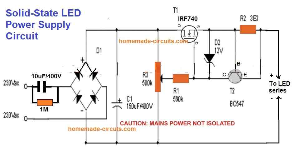
R2 can be calculated using the formula: 0.6 / Max LED current Limit
Improving the above Design
Although the above simple current controlled MOSFET LED driver looks easy and safe for illuminating high watt LEDs, it has one serious drawback.
The MOSFET can generate a lot of heat if the output is adjusted for low voltage LED strings.
The heat dissipation is basically due to the bridge rectifier and the C1 which converts the full AC cycle to DC, causing a lot of stress on the MOSFETs.
This aspect can be improved drastically by replacing the bridge rectifier with a single diode and moving the C1 capacitor parallel to the output LED, as shown in the following diagram:
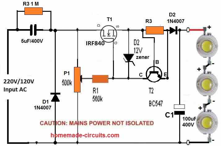
In the above diagram due to the presence a single diode D1 only half AC cycles are delivered across the MOSFET, causing 50% less stress and heat dissipation on the MOSFET.
However, the capacitor C1 parallel to the LED string ensures that the LED keeps getting the required power even during the absence of the other AC half cycles.
You can add more number of LEDs in series, a maximum upto 300 / 3.3 = 90 LEDs.
Make sure to adjust the P1 pot accordingly to adjust the output voltage to match the LED string's max forward voltage.
Likewise adjust the base/emitter resistor of T2 (BC547) to match the LED max current spec.
Using BJTs
If you do not want to incorporate a MOSFET, then you can simply build the above design using BJTs as shown below:
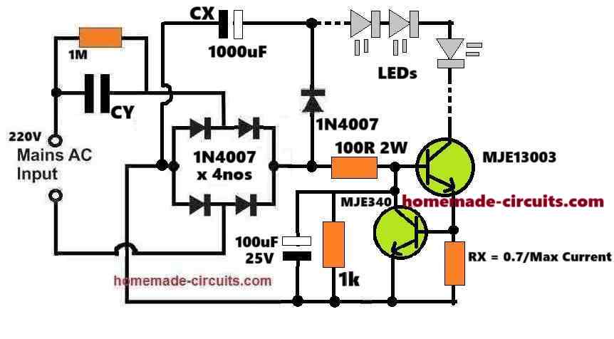
How it Works
The main feature and operation of the design is controlling current and providing a safe constant current supply to the LEDs.
So we know, if the current is restricted then the LEDs can never burn regardless of the input supply voltage.
In this design, the capacitor CY does the main current limiting operation for the LEDs. Meaning, the reactance of the capacitor produces a resistance which limits the input 220V AC current to the maximum desired limit of the LEDs.
So, if the required maximum LED current is 300 mA, then you can select and adjust the value of the CY to ensure that it never allows the input current to exceed the 300 mA.
But if the CY capacitor itself can control the current for the LEDs, then why do we need the BJT current control stage, won't it be redundant?
The BJT current controller is necessary because the input AC 220V or 120V is never constant. If the input supply rises then CY will also start passing proportionally higher amounts of current to the LEDs, eventually causing damage to the LEDs.
The BJT current controller stage makes sure that even if the input AC supply happens to increase, it limits the excess current and ensures a constant current for the LEDs consistently and safely.
Moreover this BJT current controller stage also controls the switch ON in rush current making sure the LEDs are never subjected to any form of dangerous current inputs from the AC mains.
Calculating the Part Values:
Provided Data:
Input Voltage: 220V AC
LED Configuration: Let' us assume, 50 LEDs are in series
- Forward voltage per LED(VF) = 3.3V
- Total forward voltage VLEDs = 50 * 3.3=165V
LED Current Requirement: 300 mA (0.3A)
Capacitor CX: Acts as a filter for rectified DC voltage
CY: Limits the AC current to 300 mA
Transistors (MJE13003 and MJE340): Used as current regulators
Resistor RX: Used to calculate current regulation
Step 1: Capacitor CY for Current Limiting
The current through CY depends on its capacitive reactance XCX and the input AC voltage.
The formula is:
ICY = VAC / XC
Where:
XC = 1 / (2 * π * f * C)
For 50Hz mains frequency:
CCY = ICY / (2 * π * f * VAC)
Substitute:
CCY = 0.3 / (2 * π * 50 * 220)
CCY = 4.33 µF
Select CY = 4.7 µF (400V AC-rated).
Step 2: Resistor RX for Current Regulation
The resistor RX determines the current through the BJTs. The formula is:
RX = VBE / ILED
Where:
- VBE is the base-emitter voltage drop of the BJTs, typically 0.7V.
Substitute:
RX = 0.7 / 0.3
RX = 2.33 Ω
Select RX = 2.2Ω (5W-rated for safety).
Step 3: Filter Capacitor CX
The filter capacitor CX smooths the rectified DC voltage. Its value depends on the LED current and ripple voltage. Use the formula:
CX = ILED / (2 * π * f * Vripple)
Assume Vripple = 5V:
CX = 0.3 / (2 * π * 50 * 5)
CX = 191 µF
The voltage rating of CX must be higher than the total forward voltage of the LEDs, which is 165V.
Select CX = 191 µF (200V-rated). 1000uF is not required as shown in the diagram.
Step 4: Calculating the MJE13003 Base Resistor (100 Ω is wrongly shown in the diagram)
Collector Current (IC): 300 mA (LED current).
Current Gain (hFE) of MJE13003:
Typical hFE for the MJE13003 is around 8 to 10 at IC = 0.3A. Let’s use hFE = 10 as a conservative value.
Base Current (IB) Requirement:
The base current is given by:
IB = IC / hFE
Substituting:
IB = 0.3 / 10 = 0.03 A (30 mA)
Base-Emitter Voltage (VBE):
The base-emitter drop for MJE13003 is typically 0.7V.
Available Base Drive Voltage:
We will assume that the circuit supplies 165V rectified DC (across the LEDs and CX), because of the current limiting the 310V DC peak voltage from the 220V AC RMS will be forced to drop to the level of the LED total forward drop value. So, let us assume a standard voltage available at the base resistor is 165V.
Base Resistor Value (RB)
The base resistor limits the base current. Using Ohm's law:
RB = (Vbase - VBE) / IB
Where:
- Vbase = 165 V
- VBE = 0.7 V
- IB = 30 mA
Substituting:
RB = (165 - 0.7) / 0.03
RB = 164.3 / 0.03 = 5476.67 Ω
Power Rating of Resistor
The power dissipated by the resistor is:
PR = IB2 * RB
Substituting:
PR = (0.03)2 * 5476.67
PR = 0.09 * 5476.67 = 492.9 mW
Select a resistor with a slightly higher power rating for safety.
Resistor Value: Closest standard value = 5.6 kΩ.
Power Rating: 1W or higher (to handle power dissipation safely).
Step 5: Voltage Ratings of Components
Diodes (1N4007):
- Voltage rating: 1000V
- Current rating: 1A (sufficient for 300 mA)
Transistors:
- MJE13003: Suitable for high voltage switching
- MJE340: Handles low-side switching
LED Voltage Drop:
- Total forward voltage: 165V
- Ensure capacitor CX and diodes can handle this voltage
Finalized Component Values:
- CY = 4.7 µF (400V AC-rated)
- CX = 191 µF (200V-rated)
- RX = 2.2Ω (5W-rated)
- MJE13003 Base Resistor = 5.6 k (100 Ω is wrongly shown in the diagram)
- 1N4007 diodes: 4 pieces for rectification
- MJE13003: High-voltage transistor
- MJE340: Low-side current regulator
LED Bulb with Many Series LEDs
The next circuit of a LED bulb explained below is easy to build and the circuit is fairly reliable and long lasting.
The reasonably smart surge protection feature included in the circuit ensures an ideal shielding of the unit from all electrical power ON surges.
How the Circuit Functions
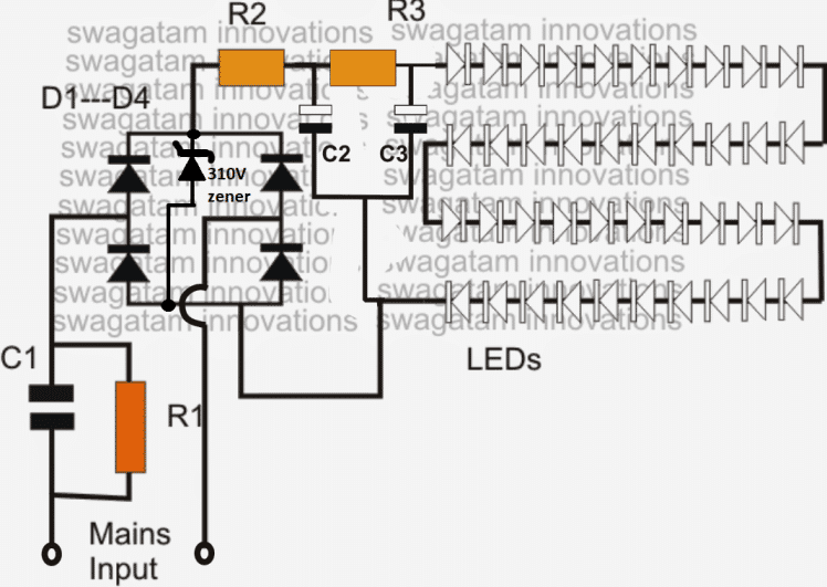
- The diagram shows a single long series of LEDs connected one behind the other to form a long LED chain.
- To be precise we see that basically 40 LEDs have been used which are connected in series. Actually for a 220V input, you could probably invorporate around 90 LEDs in series, and for 120V input around 45 would suffice.
- These figures are obtained by dividing the rectified 310V DC (from 220V AC) by the forward voltage of the LED.
- Therefore, 310/3.3 = 93 numbers, and for 120V inputs it's calculated as 150/3.3 = 45 numbers. Remember as we go on reducing the number of LEDs below these figures, the risk of switch ON surge increases proportionately, and vice versa.
- The power supply circuit used for powering this array is derived from a high voltage capacitor, whose reactance value is optimized for stepping down the high current input to a lower current suitable for the circuit.
- The two resistors and a capacitor at the at the positive supply are positioned for suppressing the initial power ON surge and other fluctuations during voltage fluctuations. In fact the real surge correction is done by C2 introduced after the bridge (in between R2 and R3).
- All instantaneous voltage surges are effectively sunk by this capacitor, providing a clean and safe voltage to the integrated LEDs at the next stage of the circuit.
CAUTION: THE CIRCUIT SHOWN BELOW IS NOT ISOLATED FROM THE AC MAINS, THEREFORE IS EXTREMELY DANGEROUS TO TOUCH IN POWERED POSITION.
Circuit Diagram#1
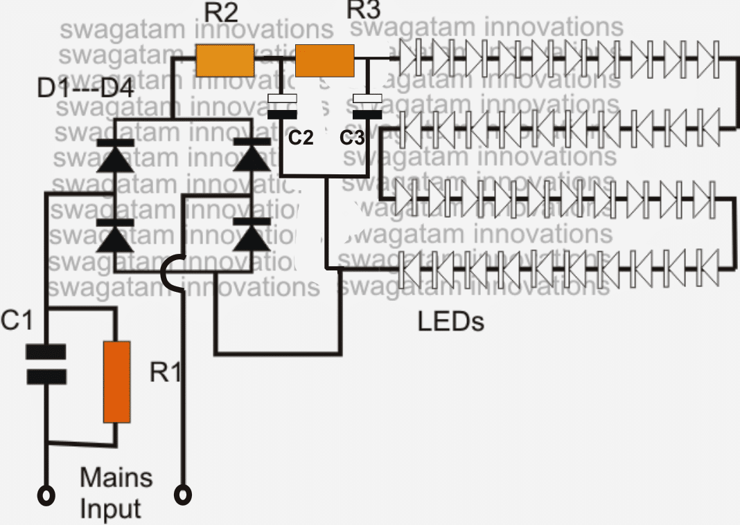
Parts List
- R1 = 1M 1/4 watt
- R2, R3 = 100 Ohms 1watt,
- C1 = 474/400V or 0.5uF/400V PPC
- C2, C3 = 4.7uF/250V
- D1---D4 = 1N4007
- All LEDs = white 5mm straw-hat type input = 220/120V mains...
The above design lacks a genuine surge protection feature and therefore could be severely prone to damage in the long run....in order to safeguard and guarantee the design against all sorts of surge and transients
The LEDs in the above discussed LED lamp circuit can be also protected and their life increased by adding a zener diode across the supply lines as shown in the following image.
The zener value shown is 310V/2 watt, and is suitable if the LED light includes around 93 to 96V LEDs. For other lower number of LED strings, simply reduce the zener value as per the total forward voltage calculation of the LED string.
For example if a 50 LED string is used, multiply 50 with the forward drop of each LED that is 3.3 V which gives 50 x 3.3 = 165V, therefore a 170V zener will keep the LED well protected from any sort of voltage surge or fluctuations....and so on
Video clip showing an LED circuit circuit using 108 numbers of LED (two 54 LED series strings connected in parallel)
High Watt LED Bulb using 1 watt LEDs and Capacitor
A simple high power LED bulb can be built using 3 or 4nos 1 watt LEDs in series, although the LEDs would be operated only at their 30% capacity, still the illumination will be amazingly high compared to the ordinary 20mA/5mm LEDs as shown below.
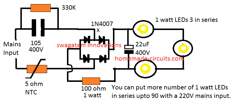
Moreover you won't require a heatsink for the LEDs since these are being operated at only 30% of their actual capacity.
Likewise, by joining 90nos of 1 watt LEDs in the above design you could achieve a 25 watt high bright, highly efficient bulb.
You may think that getting 25 watt from 90 LEDs is "inefficient", but actually it is not.
Because these 90nos of 1 watt LEDs would be running at 70% less current, and therefore at zero stress level, which would allow them to last almost forever.
Next, these would be comfortably working without a heatsink, so the entire design could be configured into a much compact unit.
No heatsink also means minimum effort and time consumed for the construction. So all these benefits ultimately makes this 25 watt LED more efficient and cost effective than the traditional approach.
Circuit Diagram#2
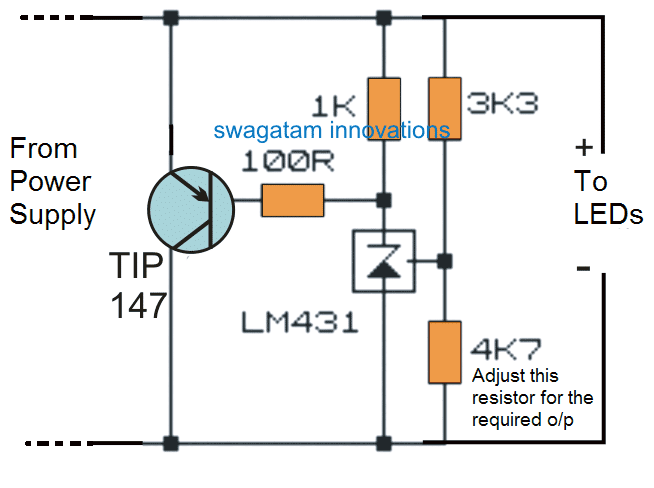
Surge Controlled Voltage Regulation
If you require an improved or a confirmed surge control and voltage regulation for the LED bulb, then the following shunt regulator could be applied with the above 3 watt LED design:
Video Clip:
In the videos above I have purposely flickered the LEDs by twitching the supply wire just to test ensure that the circuit is 100% surge proof.
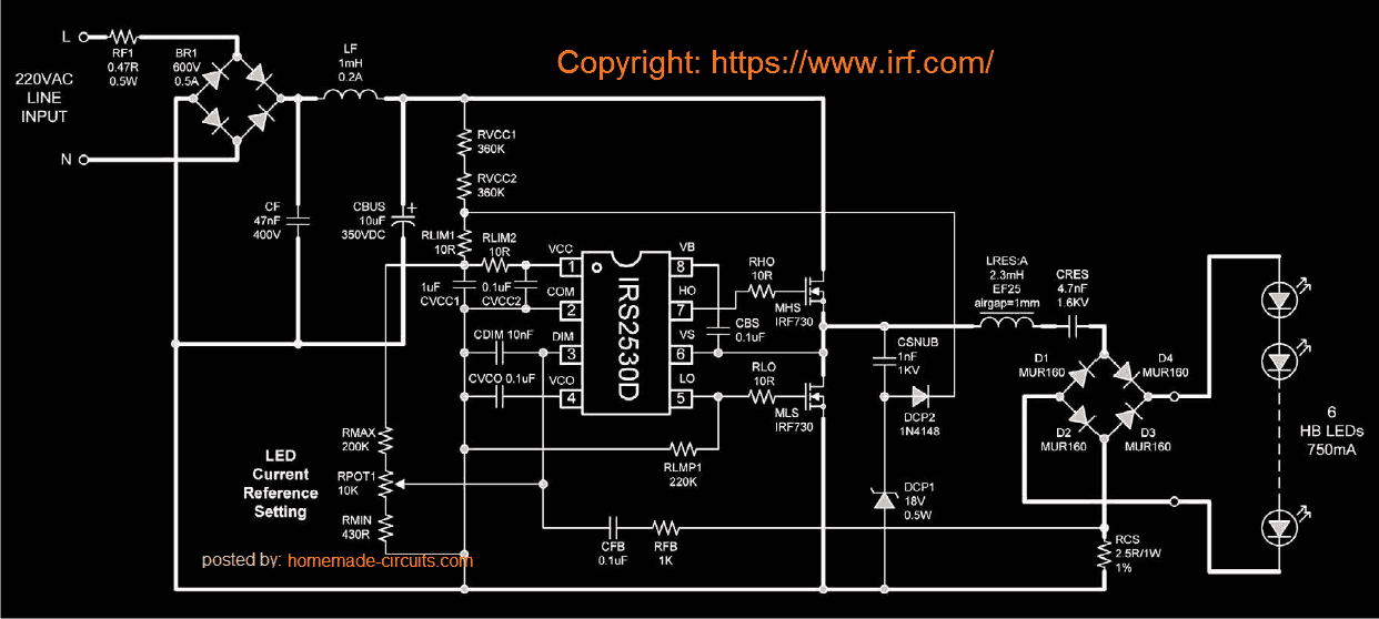
Solid State LED Bulb Circuit with Dimmer Control using IC IRS2530D
A simple yet efficient mains transformerless solid state LED controller circuit is explained here using a single full bridge driver IC IRS2530D.
Highly Recommended for you: Simple Highly Reliable Non-Isolated LED Driver - Don't Miss this, Fully Tested
Introduction
Normally LED control circuits are based on buck boost or flyback principles, where the circuit is configured to produce a constant DC for illuminating an LED series.
The above LED control systems have their respective drawbacks and the positives in which the range of operating voltage and the number of LEDs at the output decide the efficiency of the circuit.
Other factors like whether the LEDs are included in parallel or series or whether they need to bedimmed or not, also affects the above typologies.
These considerations make these LED control circuits rather dicey and complicated.The circuit explained here employs a different approach and relies on a resonant mode of application.
Though the circuit does not provide direct isolation from the input AC, it has the features of driving many LEDs with current levels as high as 750 mA. The soft switching process involved in the circuit ensures greater efficiency to the unit.
How the LED Controller Functions
Basically the mains transformerless LED control circuit is designed around the fluorescent lamp dimmer control IC IRS2530D. The circuit diagram shows how the IC has been wired up and how its output has been modified for controlling LEDs in place of the usual fluorescent lamp.
The usual preheating stage required for a tube light utilized a resonant tank which is now effectively replaced by a LC circuit suitable for driving LEDs.Because the current at the output is an AC, the need of a bridge rectifier at the output became imperative; this makes sure that current is continuously passing through the LEDs during every switching cycle of the frequency.
The AC current sensing is done by the resistor RCS, placed across the common and the bottom of the rectifier.This provides an instant AC measurement of the amplitude of the rectified LED current.The DIM pin of the IC receives the above AC measurement via the resistor RFB and capacitor CFB.
This allows the dimmer control loop of the IC to keep track of the LED current amplitude and regulates it by instantaneously varying the frequency of the half bridge switching circuit, such that the voltage across the LED maintains a correct RMS value.
The dimmer loop also helps to keep the LED current constant irrespective of the line voltage, load current and temperature changes.Whether a single LED is connected or a group in series, the LED parameters is always maintained correctly by the IC.
Alternatively the configuration may also be used as a high current transformerless power supply circuit.
Circuit Diagram#3
Original article can be found here
Why use LEDs
- LEDs are being Incorporated in vast magnitudes today for everything that may involve lights and illuminations.
- White LEDs have especially become very popular due to their mini size, dramatic illuminating capabilities and high efficiency with power consumptions. In one of my earlier post I discussed how to make a super simple LED tube light circuit, here the concept is quite similar but the product is a bit different with its specs.
- Here we are discussing the making of a simple LED bulb CIRCUIT DIAGRAM, By the word "bulb" we mean the shape of the unit and the fitting secs will be similar to that of an ordinary incandescent bulb, but actually the whole body of the "bulb" would involve discrete LEDs fitted in rows over a cylindrical housing.
- The cylindrical housing ensures proper and equal distribution of the generated illumination across the entire 360 degrees so that the entire premise is equally illuminated. The image below explains how the LEDs needs to be installed over the proposed housing.
Hello,
I stumbled across this blog post recently and it remembered me about a Philips LED bulb I disassembled a while ago. Attached you can find a schematic which I’ve drawn from memory. I was wondering how it would perform compared to the demonstrated circuits above. How robust and long lived will it be? What are your thoughts?
Best,
Valentin
Hi, thanks for visiting this site and for posting the Phillips LED bulb circuit diagram. The design you provided is a basic constant current LED bulb circuit. However, the designs presented in the above article are better and are capable of providing more comprehensive current control, brightness and safety to the LEDs.
70 led bulb connect to series one led value 0.60w
plz send mi circuit diagram and part value
You can try the following circuit to power the 70 LED series LED, with some modifications: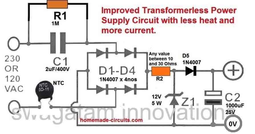
" rel="ugc">
1) Please replace the C1 capacitor with a 0.33uF/400V
2) Replace the zener diode with a 220V / 1 watt zener diode.
Remember, since the circuit is not isolated from AC mains the whole wiring can carry lethal AC mains voltages. Please build it only if you exactly know how to correctly insulate the circuit using plastic covers and plastic sleeves. Do it at your own risk
Sir can u pls give the 200leds series circuit diagram
Hello Subhrajyoti, adding 200 LEDs in series with a 220V AC supply may not be feasible, instead you can use two parallel LED strings, each having 100 LEDs in series.
Let me know if that’s OK with you or not.
High Watt LED Bulb using 1 watt LEDs and Capacitor
Firstly thank you for all your doing for this community. Its a great help. My query is:
If I am to make a 25 watt bulb with 75x1W LED, what changes do I have to make to the components.
Thank you and look forward to your reply
Best regards
Suren
You can try the following simple design. You may have to adjust the 100 ohm resistor slightly to improve the brightness on the LEDs. Also make sure to use a 250V 1 watt zener diode parallel to the 22uF/400V capacitor. You can use many 12 V or 24 V zener diodes in series so that the total sum of the zener value is around 250 v.
" rel="ugc">
Thank you for your reply. Much appreciated.
You are welcome!
sir,namaskaar 3 one watt led circuit mein 5ohm ntc ki Maan kaise nikala aur kya ye circuit ke liye surakshit hai kripya bataye
Ashu,
Please ask in English language only so that all can read and understand your question.
NTC value can be 5 ohm, it does not any calculations, since the current and voltage is auto adjusting in the 3 watt LED diagram.
If you use a zener diode then you can use the following formula for the NTC
NTC = zener value – total LED forward voltage / LED current.
there are many wifi dimmers based i.e. on ESP32 for the LED stip (5V or 12V), but I would like to use AC 230V LED stip (around 90 LEDs), with the same functionality: ESP32 inside and then on/off plus dimming – your circuit if fully passive and require pot to operate – do you have a project for WiFi operated dimmer?
thx
Sorry, presently I do not have a WiFi operated dimmer circuit in this blog.
I seek suitable module for 4vLED to be powered from 220v AC for spot light to be used by Students as study support.
Are you sure it is 4V? because LEDs are normally rated at 3.3 V. Also please provide the current rating of the LED, I will try to figure out the circuit
I have placed order on Amazon for” Electronicspices 4V 50 LED aluminium Strip Light Bulbs, Multicolour” at present this is max input i can suppliment.
OK, I checked it, but I could not get the current specifications of the board. I am assuming the LED are rated 20 mA each. In that case the total current requirement of the board will be 20 x 50 = 1000 mA or 1 amp.
You can use any mobile charger to illuminate the board through a series resistor.
The value of the resistor can be calculated with the following equation:
R = Mobile voltage – LED voltage / LED current
R = 5 – 4 / 1 = 1 Ohm 1 watt
So you can use a 1 ohm 1 watt resistor in series with any of the two wires of the mobile charger and connect it to the LED board.
Hi,
I’ve prepared the first circuit
But the mosfet got too hot and burned in 15 seconds (without heatsink)
Then I’ve added a heatsink to the mosfet and nothing has changed its still so very hot it cant last long.
What is the problem? (My driving current is aprox. 550-600mA)
Hi,
please provide LED current rating and the mosfet number….I hope the voltage of each LED is 3.3V. The zener diode value must be 12V.
The mosfet may be getting too hot due to the input/output difference which is very large…..if you increase the number of series LED to 50, 60, or 90. the mosfet be get cooler proportionately.
You either have to increase the number of LEDs, or decrease the input capacitor value, or add two or 3 mosfets in parallel
Thank you very much for your response.
at 1 and 2, i really got these. Thanks.
at 3) Where did we find this 6V value ?
Just as BJTs require 0.6 to 0.7V to turn ON, mosfets require around 5 to 7 V to begin turning ON….so the source voltage may lag behind the gate voltage by 6V
Thank you for your response.
Ima beginner
1) Where did we find this 0.6V value?
2) What is the purpose of the 12V zener diode in the circuit?
3) Please if possible may you explain little bit the circuit after the potansiometer? (Including Mosfet ,Zener , Transistor etc.) I couldnt figure it out completely.
(Again if possible, i think, it will be better if you add little more detailed explanation to the article about this last updated LED driver for the newbies like us.Thank you very much.)
1) 0.6 is the voltage level around which most BJTs, like BC547 will switch ON.
2) The 12V zener safeguards the mosfet gate by clamping the gate at 12V and avoiding excess voltage to it.
3) The mosfet is configured as a common source in which the source side voltage will be always 6 V lower than the gate voltage….so whatever voltage is supplied by the potentiometer at the gate of the mosfet, the same is replicated at the source side minus 6 V. The BC547 stage acts as a current limiter.
Is there any benefit for us of this 6V difference between the gate and the source? Or there isnt?
There’s no benefit, it is actually a drawback since the source load always gets 6V less than the gate voltage
At first circuit design;
1) ” R2 can be calculated using the formula: 0.6 / Max LED current Limit ”
Can you explain that more detailed?
2) What is the purpose of the BC547 transistor?
R2 is selected so that it develops 0.6V across itself whenever an over current is detected. This 0.6V will activate the BC547 which will short the gate/source of the mosfet shutting it off.
Can anyone Suggest best circuit diagram to control 2 LED’s blinking in 3 Modes i.e. When we press a button both glow continuously, when we press again both LED’s start Blinking & finally when pressed again Alternate blinking of both LEDs.
This can be done through an Arduino only, analogue circuit can be too complicated.
I am trying to figure out how to improve the existing power supply on chandelier in my house. There are 58 number of LED straw hat type in string connected to power supply. I find the LED burn out often on switch off/on. I have drawn the connections based on PCB. I can send photo of the connections of various components if I can get your email Id
It’s probably due to a capacitive power supply involved with the LED circuit. If an SMPS circuit is used this problem will never happen.
For sending an image you can upload it to any “free image hosting site” and provide the link to me. I will check it out.
Make sure to remove the http otherwise the comment will be sent to the spam folder.
The polarities of D1—D4 in the diagram are incorrect. The polarities should be just the opposite.
Please connect the zener diode D5 to protect the LEDs from damage. The value of the zener voltage will depend on the total series forward voltage drop of the LEDs
The zener is also vulnerable to the current surges, but here it is protected by R3, so nothing to worry.
R4 can be replaced with a jumper wire.
I will definitely try your suggestion. Based on number of led 58, 58 x 3.3 = 191.4 , zener 190v 2w rating should suffice. Please confirm.
yes, that looks perfect to me, you can go ahead with a 190 V 2 watt zener diode.
Is it possible to make a 25 watts led with a life time warranty.(I mean it would last for like more than 20 years)
yes that’s possible, if the zener diode is correctly selected and correctly rated
Hello sir I have run 20 1 watt led from 2nd. Circuit diagram but in the circuit 100 ohms 1 watt resistor is heating too much wat will be the solution for that pls tell thank you
Abdul the first and the second circuits are for 20 mA LEDs. You can use the second circuit by replacing the R2, R3 resistors with 10 ohm 2 watt each resistors. For the zener use a 70 V zener 5 watt.
For the input capacitor use a 5 uF/400V capacitor
sir i want transformerless suply for high led street light circuit details. in emergency i wat use them. Also spd circuit design for led lights and how to conncnt LDR in led light in internal or external.
Hello Sir, I want to build a 9watt led bulb driver at low cost. Can you please suggest any.
Rahul, please provide the voltage rating of the LED
I have an emergency light consisting of 90 led
Inside I found one circuit board but it is damaged
This board is not available in my country, can I use a board attached to another emergency light but it illuminates 60cm fluorescent lamp
With a modification in circuit
Sorry for my poor experience and knowledge
The fluorescent driver cannot be used to replace the LED driver, unless the voltage and current parameters are correctly matched.
I’ve been told by my course director that I need to design driver circuit for led used on domestic and commercial lighting.
but I don’t know where is the challenge.
do you have any advice or what can I do ? or what are the difference?
many thanks
What is the wattage specification of the LED that you intend to apply?
There is no specific Watts.
You can try this circuit
https://www.homemade-circuits.com/simple-220v-smps-buck-converter-circuit/
hi good day sir,
we need to output voltage 3v to 80v
input voltage ac 240VAC
we make universal led driver
so any of circuit suggestion
Hi Rajesh, I think you should try the last circuit from the above article
Hi, On COB LED bulb we need a surge of 471kD07 MOV. But is there any alternative if you cannot find one MOV mentioned above?
Hi, you can use TVS diodes or NTC thermistor
Good day sir, please for the shunt regulator with transistor tip147, please where can I put led bulb to light up when adjusting to a desired output.
Adeyemi, it is already shown in the diagram..
Hello,
By the way, I have got 1no 150u/ 400v electrolytic, 1no 470u/ 400v electrolytic, 2nos 1u/400v ceramic, and 1no 2u/275v skt capacitors at hand. How could I place them in the circuit? Thank you!!
Eric,
Hi, you can apply the second design, use the 1uF/400V for the input capacitor, and use 150uF and the 470uF for the C2, C3 respectively
Hello Swagatam,
I am interested with the power supply circuit in the configuration,
" rel="ugc">
My AC line voltage is 220v. I want to step it down to 110v as the power source, and through it to drive a treadmill motor whose rating is 110v/ 16A by means of pwm!!
In the earlier time, I was trying to power my circuit just by using a dimmer and a bridge rectifier, but I got one mosfet and one bjt burnt up!! So I suspect that It was due to the power section. What my question is does the captioned configuration work for my project? Thanks for your time!!
Eric,
Hello Eric, It may not be practical to get 16 amps from a capacitive powers supply, and moreover a capacitor will not drop 220V to 110V, so it may not be possible to use the mentioned circuit.
You will have to use a transformer for your application. You will have a to buy a 220V to 110V transformer and then you can use it safely for the purpose.
Sir i already done with increasing the frequency but i don’t able to know how to increase more frequency like 50khz, and i make voltage regulator also in this also i getting amp problem how to increase amp my leds are near by 20amp.
Pls suggest me any other led pcb design because i make 3 leds in one series in this I m getting a voltage dropage also so is any high voltage led pcb design with dimming
Pls do need full
Thanks
Alam, which pwm circuit are you using? If it’s a 555 based then you can reduce the timing capacitor value to 680pF and check the response.
For voltage regulator method you can try the following concept:
https://www.homemade-circuits.com/100-amp-variable-voltage-power-supply/
use only 3 transistors.
Sir i have 2835 led can be oprate with 3.1v to 3.4v max 20ma to 60ma, I am making 150w led bank for video shooting,i am using 12v smps and 555 pwm for dimming but their is a problem with light it having a flicker in front of camera if i connect the leds without pwm dimmer direct to smps it working well ,so pls give the solution for this or any other simple circuit for it.
Pls do need full
Thanks
Alam, Don’t use PWM, instead use an LM338 based voltage regulator circuit, this will allow dimming as well as not produce any flicker. Or may be you can try increasing the PWM frequency to 50kHz and check again
Please let me know if you’re looking for a writer for your weblog. You have some really good posts and I feel I would be a good asset. If you ever want to take some of the load off, I’d absolutely love to write some content for your blog in exchange for a link back to mine. Please send me an email if interested. Thank you!|
Will you write on topics provided by me?
Hi, I apologize if this is not rite place or if it’s already been covered. But I’m trying to power a discontinued lsi crs 64 ho petroleum canopy light. From what I no it can have 80 watts for power saving or 155 watts for high output. I’m guessing i would actually like to be able to dim it. I plan on using it under my car lift in my shop as a shop light. It has 64 less, and i would like to use 110v. I wish i could send a pic of board. I took one apart b4 i figured out i needed a separate driver. Any help would b greatly appreciated
Hi, could you please specify how the LEDs are operated, meaning its voltage and current specifications. I’ll try to figure out.
Please how can I use this circuit for 12v led bulbs circuit to regulate the supply to the bulbs at peak sunshine because the high voltage damages the bulbs
Please specify voltage/current of the panel, and voltage/current/quantity of the LED bulbs
360 w panel used for my home. 12v 4w bulbs 5pcs used with inverter
You can use the first circuit. Instead of 10uF/400V use a 6uF/400V capacitor. If the LEDs are intended for the same room, then you can connect them in series with the same circuit for maximum efficiency.
Hi Swagatam,
I am trying to learn more about SMD transformers to use them in led powering circuits, Which are mostly found in led light bulbs or trimmers. Can you share me a link or a website where I can find more design based information on it?
Or can you make me explain more on it?
I have used those normal transformers in many college based projects, but now I would love to learn more on smd transformers. I am not getting more designed based information on it. Also getting confused with the number of pins those different transformers has.
Any help would be really appreciated, I have just cleared my B.E so still a student not a professional guy! 🙂
Hi Mehul, Are you referring to the ferrite core based inductors? They come with different pin specs and winding data for different circuits depending on the IC number or the circuit configuration. Ferrite based inductors are not easy to calculate, it requires many parameters to be taken care of and then calculated. I have a couple of related articles which are given below:
https://www.homemade-circuits.com/how-to-design-a-flyback-converter-comprehensive-tutorial/
https://www.homemade-circuits.com/ferrite-core-material-selection-guide-smps/
Hi Swagatam, Thanks for your kind and valuable reply yes I am looking for ferrite core based inductors (I guess also known as smd transformers, if I am not wrong). I will surely take a look at these contents.
Thanks again.
Thanks Mehul, yes they are also called SMD transformers, wish you all the best!
Hello sir I have 5mm 9v leds dome dip I have to connect 50 leds in series to 230v ac main wat will be the circuit for that
Hello Abdul, can you please specify the current rating of the LED, and is it an assembled module with a resistor, or is it a single isolated LED without resistor?
Hello sir it’s current amps is 20ma ……and it is not assembled with resistor …..it is single isolated led without resistor
OK in that case you can try the second circuit from the above article. Put all the LEDs in series, and for the zener diode use a 160V 1 watt zener diode.
The zener number is NTE5101A
Is there no need of filter capacitor at the op? If yes, which capacitor can use for a 90mAh 230V op ?
The filter capacitor is present in the form of C2, C3. Those are enough for the mentioned application
Sir, I would like to make a transformer less power supply with 2.2mfd/400v capacitor. I hope i will get aprox 140ma.current. the op voltage is to be lowered to 50v. Here what value of filter capacitor is to be used?
Aravinth, my site is having problems, please comment again afterwards, I’ll surely help you
please my corn lamp is blinking. the LED are not constant.. plz what could be the problem?
which circuit have you used?
Hello,
I need to build led driver .Please help me for the circuit to make it.Is it possible to make led driver with both possibile input AC/DC?
1
INPUT VOLATAGE RANGE
70-140 VDC / VAC
2
OUTPUT VOLTAGE
15 VDC
3
OUTPUT CURRENT 1
3 Amp
4
OUTPUT CURRENT 2 (WITH DIMMING FUNCTION)
2.5 Amp
5
SURGE PROTECTION
1.8KV, 1.2/50 µsec
6
WORKING TEMP
0°C to 85°C
7
PROTECTION :
Short circuit
7.1
open circuit
7.2
reverse polarity input
7.3
over voltage
7.4
under voltage
7.5
EMI / EMC PROOF
8
OUTPUT WATTAGE
15VDC X 3 AMP = 45W
Sorry I do not have a 3 amp SMPS circuit with me at the moment, I would rather suggest you to buy one ready made and reverse engineer it and identify its full construction details
Sir, some of my LEDs are not glowing. Could you please tell me what can be the reason for this.
Rishabh, it could be either the LEDs are of bad quality and therefore not illuminating or they are burnt due to surge current….please use a zener diode as suggested in the last circuit, and also an NTC if pssible
Dear Sir,
Could you please tell value of inductor coil used in Philips 5 watts led bulb (which is burnt due to power fluctuation)
Dear Ravi, without practically checking the design it can be difficult to understand the correct specs of the coil…
Dear Sir,
I have made your circuit to power up my 100LEDs with 25LEDs in series and 4×25 LEDs in parallel. Its working fine. Just a concern. Shall I put a current limiting resistor on every 25LEDs branch. I tried putting 6.8K 1W and its getting quite warm. I am using the christmas Light LEDs C6 E10 0.1W 15mA. Your advise is greatly appreciated.
Dear Reeko, I am glad it's serving the purpose for you…however the 474 capacitor won't generate more than 25mA, therefore it's strange if the resistor is getting warm.
Don't use 6.8K because it's too high, use 100 ohm 1 watt and see the difference.
alternatively, you an make just two channels each having 50 LEDs, that would make the design even more efficient, cooler and brighter.
If I have to reduce the no. Of LEDs to 4 hence what is the resistor I have to connect in series??
Can you please give the calculation if possible ckt diagram.
replace C3 with a 15V/1 watt zener diode, no other changes would be required, assuming your LEDs are 20mA type
Dear Swagatam,
I made this circuit and its absolutely working fine.
I am an electronic hobbyist and want to learn in electronic and enhance my knowledge on field of electronics and circuit. Please could you recommned any book or tutorial. I was not PCM student.
Thanks again.
Rgds
Sagar
Thanks Sagar, I am glad to know this.
There are plenty of books and tutorials online, you can elect any of these as per your convinience
I want to drive 3v 150ma leds. I have connected 3 leds in parallel and have connected 24 such parallel leds in series. I wanna know whether this circuit will suit my requirement?. Also kindly tel me the current output of your circuit.
No it won't….you will need to connect all the LEDs in series for making it work with this circuit…and for 150mA you may have to use 1uF/400V x 3 capacitors in parallel instead of the shown 474/400V
Sir i want to make a sign board like "Welcome" with 555 and 4017.I will need seven strings ,each consisting of max 38 LEDs in series.Can i use this supply circuit ? Can you please refer me to such a circuit diagram…
Asif, you can use the first circuit idea from this link
https://www.homemade-circuits.com/2013/03/sequential-bar-graph-turn-light.html
it is designed for 6 outputs but you can easily modify it with 7 outputs, if possible I'll try to post it in new article.
hello Swag good morning. pls am new here and my questions might sound so childish but i really want to learn from this blog. please Sir i want to design a 36W LED bulb with 220-240V input without a transformer. please advice kindly. thanks
Thanks egerega, you can try the following concept
https://www.homemade-circuits.com/2016/07/scr-shunt-for-protecting-capacitive-led.html
just replace the 12V zener with a 120V zener diode and use 36nos of 1 watt LEDs in series at the output
the 1K resistor might also require some modification
Hi,
I have 15 No's of white LED 5mm, would it work on the same circuit as you advised?
yes it will….just make sure to use an NTC at the input side.
hello…..please suggest me….how can i calculate the valve of c1,c2,r1,r2…for different watt level of led bulb….how can i built transformer less rectifier circuit…????
R1, R2 combined value can be calculated by the following formula
Supply voltage input minus Total LED FWD drop divided by LED current rating
capacitor value calculation is not important, but higher value will give better results.
however the professional of combating surge current is to include a NTC thermistor at the input mains side, as I have explained below
https://www.homemade-circuits.com/2013/02/using-ntc-resistor-as-surge-suppressor.html
Please reply how to make led in home use 3volt, 5 volt, 9volt, please reply and what's the parts needed, to make it
which type of LED??
Help sir ,how to connect 8 mm 50 nos led,s to 220 AC supply.which value resistance ,capacitor and diode for need that connection.
Kiran, you can use the same circuit which is shown above if the current rating of the LEDs is 20mA, if it's more then you may have to increase the input capacitor value accordingly
Hi Sir … I see this is an old post, but I want to know:
Here in Mexico we only have 120v. What changes I need to do to this circuit to make it work?
Thanks!!
Hi David, you can use the same circuit for 120V supply also, but more than 40 LEDs cannot be accommodated in series, ….upto 40 LeDs will work nicely
Hi, whats that circuit lumen?
Hi, I find your circuit interesting and I modeled it up in everycircuit with 16 LED's (5630 type). But in the simulation the current through the LED's is far too high, this is only resolved if I reduce the 500nF capacitor to about 1.2nF.
everycircuit.com/circuit/4562220067848192
Can you explain how this works, I can see that the input capacitor's reactance is being used as a voltage divider, but then surely the capacitors value needs to be adjusted for the number of LED's and the unput voltage?
Hi, that's why I consider simulators useless….and I never use them.
0.47 is supposed to provide around 35mA current to the indicated 20mA LEDs, the excess 15mA could be dropped by the series resistors, in fact it could drop the current below 20mA I have not calculated it….but 0.47 is an optimal value…..
for 5630 LEDs, even the 0.47uF won't be sufficient, since these are rated at 1/2 watt and would require around 150mA current…that's huge and could call for a capacitor as high as a 2.5uF for achieving optimal performance in the above circuit.
Respected sir.,
1. pleas tell me i want now the difference between ntc and vairistor(mov)?
2. Can i use 10D431k mov ?
Satheesh, both are surge suppressors, NTC is connected in series with one of the mains input supply lines while MOV is connected between or across the supply lines.
the specified MOV is not a good choice due to its higher clamping voltage spec (700V)…..it should be around 300V not above this.
the image shared on g+ already, pls chk it, I am waiting.
thank you 🙂
give me the link.
https://drive.google.com/file/d/0B2l5VansvCMBSzZhN1MteVA1aFE/view?usp=sharing
yes it looks OK to me, just reduce the values of R2, R3 to 10 ohms 1 watt for better illumination, rest all is perfect, but 1 watt LEDs will not work…will produce lower illumination
You told me to reduce R2 & R3 value from 50ohm to 10ohm for 1 watt led,,
if I use 8m straw hat type led so I will get proper illumination??? and no need to change any parts value????
the written on 8mm led is: 3-3.3v 0.35w. I hope its not more then 25ma.
so I can use 8mm led for better illumination and proper brightness.
yes that's right you will get better illumination with straw hat LEDs, but keep R1/R2 = 10 ohms….50 ohm could decrease the illumination a bit
HI Friend…
I want to ask something here, you mentioned 40 Led's (white 5mm straw-hat type) on your circuit,
my question is:-
1. Can I use 1w led's instead of 5mm straw-hat type?
2. If yes then how many 1w led's I can use with this circuit? (without any changes circuit parts)
3. What is the minimum & maximum life of this circuit?
4. This circuit can handle low voltage?? (Due to rainy season you know sometimes we get low voltage in home. or If E.B workers works on the sreets and sometimes they try to connect line and we can see the voltage flick 2,3 times)
Thanks in advance…
Hi friend,
yes you can use 1 watt LEDs, anything between 40 and 90 LEDs in series can be tried….but you may have to increase the input capacitor value to 3uF/400V.
the circuit life is permanent, but the LEDs can get burnt if an NTC or any other suitable surge limiter device is not included..so you need to include one at the input
The low voltage handling range will depend on how many LEDs are used in series….40 LEDs will allow upto 140V AC input drop…and so on
Thank you SM, for vry quick reply,,
I have few little doubt, I hope u will clear.
1. I don't know what is my 1w led current, generally 1w led current is 300 to 350ma, but mine I don't know whether it is really 300/350ma or what…. so how to know the led current value? any calculation?
2. you told me to put NTC at the input, :- what value of NTC I have to put? I mean what rating of NTC?? & and I am confused where to put NTC exactly….
This circuit is work well with 5mm @20ma normal led's… but I want to run 1w led's. pls clear my above doubts
Kmalesh, if you are saying it's 1 watt then obviously its current is 300mA, as per the following formula:
P = I x V
1 = I x 3.3
I = 1/3.3 = 0.3 or 300mA
for NTC connection and spec detail you can refer to the following article and use the one shown there:
https://www.homemade-circuits.com/2013/02/using-ntc-resistor-as-surge-suppressor.html
consult with your electronic dealer regarding the number of the NTC, to be on the safer side
Oh thankssssssssssssss.
I got it… ur great… I got it, the NTC should be put before c1(c1 and r1 as shown on ur above link article 1st picture).. you shown NTC value is 5D 11 (5ohm 11mm). you mean I an use NTC 5d 11,, Ok I will do and check, if any issue, I will free to text you.
Thank you very much friend….
I made this circuit but still not put in mains, before I put in mains, I want to show you, please click this link to see circuit
https://drive.google.com/open?id=0B2l5VansvCMBSzZhN1MteVA1aFE
rply soon,
Thank you FRIEND 🙂
yes, according to me you can use 5D11 NTC for your application….the link is not opening because you might not have toggled the "share" option….tick the box and resend the link
hello Swagatam can you help me with a grow lamp diagram 200 LED 3 watt direct 220
best regards walter
hello Swagatam
Please I need your help for a diagram for a LED grow lamp ,direct power 220 volts
4 red 1 blue all 3 watt LED , I would like to have 200 LED to create 600 watt
hello walter, I think I have answered to this question somewhere previously,
anyway, you'll need an SMPS for driving 3w LEDs, you can't drive directly from 220V
Dear sir.
I'm SHRiNiVAS,
first of all, I've no words how to thank you for all this. Bcoz I'm art student so electronics is thousands of miles away from my academic career. Bt your blog made me able to build circuits with full understandings.
I've made this circuit with 90 LEDs. I'm getting so good illumination. I've also made your 1W single LED 220V AC circuit. Both are running very well. Now I want to attach only single 5mm LED to this 1 watt circuit. Actually I have posted you this requirement in the comment in that 1W circuit page bt maybe it couldn't reach to you or you may angry with me. Bcoz I couldn't got your reply. Well, if you got this message, please suggest some modifications in your 1W 220V AC circuit to attach only single 5mm white LED with safe brightness according to its durability.
I hope my this effort won't be wasted.
Thank you sir.
Dear Srinivas,
I have replied to your previous comment also….please press the "load more" button to see hidden comments on pages which have more than 200 comments.
for a single 5mm LED you just need to change the input capacitor value to 0.33uF/400V that's all….
Hi friend,
exactly i was waiting for this…….
I seen ur 1st diagram, you shown 40 led connected in series. i want to ask you that if the single led 1w x 40 (3v) (in series) = 1w, 120v. Ok means watt will be the same only volt increased, but by my thinking its equal to 40w brightness… am i right??????
next question is: which is the best?? >>> led in series or led in parallel ???
next question is: this above circuit is durable? (long lasting) (if all parts purchased new from market, not from recycle)
Thank you,
Hi friend,
1watt led will not provide enough light because the current is too less in this circuit.
but if you connect 5mm LEDs and use 50 LEDs then that would provide equivalent to 3 watts of light…so it's better to use 5mm LEDs than 1 watt LED
use an NTC….or an MOV at the input f the circuit…then it'll be long lasting and reliable
in the above type of designs, series is always better, but for 12V adapters parallel is better…
Hi much respect to you for answering all the questions.
I have 1cm square 12v 10w leds, can I use this circuit or would I need to change some values?
Thank you
thanks time&space, the above circuit is only for low current LEDs, for a high watt LEd such as yours, a 12V 1amp SMPS would be recommended
Thank you for your reply, so if I want to put 30x 12v 10w should I put them in parallel with a 12v SMPS?
yes you can do that, but the 12V SMPS will need to be above 30 amp rated, or you can even try a 0-12V/50amp transformer for the same after aptly rectifying the output to a pure DC.
a current controller circuit would also be required, but you can skip this by making use of a fan cooling behind the LED heatsink.
the specification of led is 50mA generally, bu you managed 100mA output at leds.. ???
Hi, yes you can use 20 LEDs with the shown circuit.
no changes would be required in the circuit, if you see the resistors getting warm reduce it to 10 ohms each.
connect a 80V/1 watt zener across C3.
NTC/MOV can be used for extra safety, although technically the zener alone would be enough for the protecting the LED from current surges.
NTC/MOV may be rated to control 100V (clamping voltage)
You are doing an awesome work and really helped me a lot.
https://www.homemade-circuits.com/2012/04/how-to-make-led-bulb-circuit.html
My requirement is to design 5630 leds (30 leds in series 70 leds in series) numbers.
What would I need to change in circuit if I have to increase forward current to 150mA, and what other things needs to be modified to make circuit reliable
Thanks Sri, you can simply increase the input capacitor value to 2uF/400V for getting 150mA.
However make sure to use an NTC thermistor at the input and also if possible a 200 to 500 turn coil over any iron core in series with the LED string
Hello sir I want to run 300 leds of 5mm or 8mm to 230v AC main of 6 series in parallel each series of 50 leds so wat will be the changes for the circuit
Hello Basit, for this you may have to increase the input cap value to 2uF/400V by connecting two 105/400V in parallel, rest everything can be left as is.
make sure each string has its own series a 22 ohm 1 watt resistor or any value between 15 and 30 ohms
Hello sir I want to run 300 leds of 5mm or 8mm to 230v AC main so wat will be the changes for the circuit
use 4nos of 75 LED string and connect them in parallel, no changes would be required in the existing design
How much nos of smd led will work for this circuit and if I want to connect 100 nos of smd leds what will be the changes for the circuit
please check the above comment
Sir how much number of smd led will work for this circuit and if I want to connect 100 nos of smd led in series wat will be the changes for this circuit
Basit, since the maximum available voltage from the 220V input after rectification will be 330V so dividing this by the forward voltage of the LED gives 330/3.3 = 100
so yes 100 LEDs will be just OK and can be connected in series,
no changes will be required in the design.
buna ziua domnule swagatam.cum pot face o lampa la 220v cu banda leduri auto de 12v.un exemplu de conectare leduri.multumesc anticipat.
gogutu I id not understand your question, is your question about how to run a 220v strip light on 12V???
can i use 5630 with this circuit
yes you can use it
Dear sir.
I build this circuit successful.but switch off time bulb instal in bulb holder. then bulb very very dim illuminate .
1.why did it happen?
another matter
2.can I increase bright in the circuit?
Dear Hassan,
i did not understand your query: ….."but switch off time bulb instal in bulb holder. then bulb very very dim illuminate"
use more number of LED in series to increase the illumination…use at least 60 LEDs to make it bright and safe.
also use a coil in series with the positive line….the coil can be made by winding 200 turns of 0.5mm magnet wire over an iron nail or bolt…this will prevent the initial surge current from entering the circuit
sir
1.can I use and smd type LED(20 nos.)in the circuit?
2.can I do it a homemade business ?
Pls reply sir
yes smd LEDs can be used.
for commercial production you may should prefer an SMPS design for reliability.
Sir'
Will I give resister with LED?
R2 and R3 are already present so no more resistors would be required.
sir.
mey 2nos 5w led se 10w lamp banana chata hu.cap power se. sir yea circuit me keya change kerna parega.
plz sir
orrie, capacitor power supply will not work for this, you'll need an an SMPS for it
hi sir i need 8mm led(3.2v,50ma)drive circuit.
For how many LEDs?
hello dear mr Swagatam Majumdar
first of all i want to thank you for making such good blog and let us know how to make incribble things.
i have some question from you i hope i could have my answers.
i maked this circuit and two other circiuts too
i want to choise best and the one that is smallest and taking little space
first of all i want to ask : can i run 20 or 18 or 38 smd leds (5730 model)on this circut?
if i want to reduce leds to 18 what prameter should be change?
if the leds goes up there will be changes in cureent and volatage too.
but i want to this circiut delevery me 19 mA and 3.2 v for every led.
you said cureent output will calculated by ractounce formula : Xc = 1/2(pi) fC
if circuit eleverys 70ma out put will this burns leds?
how should i controll the amp that pass leds? should i use resistor?
if i use resistors thre will be voltage drops too. you said useing output cureent will drop mains from 308 to 0 !
i`m a little bit of confused i`ll be thanks ful for your answrs.
thank you again for your time.
thanks Hz021,
you can use the number of LEDs as per your requirement, just make sure the current requirement of the LED string matches with the capacitor's current delivering capacity.
This can be calculated using the reactance formula which I have comprehensively covered in one of my recent articles.
Resitor can be used for controlling current but calculating the capacitor value correctly is recommended for ensuring proper efficiency and safety of the LEDs.
All's been explained in the following article
https://www.homemade-circuits.com/2015/01/calculating-capacitor-current-in.html
Additionally you may also want to include an NTC thermistor in order to arrest the switch ON surges which sometimes become the major cause of LED burning problems in these circuits.
I bought a corn cob led lamp it won't work on DC only AC, I think because of the capacitor that would block DC. tyvm for sharing merci beaucoup
sir can you tell me what is the R1 @ R2 is calculating eqution?
Thilina, The formula is R = (V – LED Fwd volt) divided by LeD current
Hi swagatam,
I want to build this circuit. You said that if you used ntc thermistor the leds would last longer.
So what is the value of the ntc?
Sorry if my question is wrong as i'm a new electronic hobbyist who just visited your blog lately. But could you give me little light about that ntc thing for this project?
Hi Ebed,
you can use the one that's shown in the following article:
https://www.homemade-circuits.com/2013/02/using-ntc-resistor-as-surge-suppressor.html
sorry for asking too much… finally made with 40 leds, working fine bright,due to absence of zener, i got a 33D NTC from electronic ballast , it was present at i/p of supply in ballast. i used it in series with leds… lit very brightly n some leds gone. 33D cannot be used?
necessary to connect it at 230v i/p of ckt?
replace the input capacitor with a 0.22uF/400V and check the response, if the brightness is good continue with it in the circuit, it will also reduce the surge current and stop the LEds from blowing off, without the need of an NTC. if possible use a coil in series with the LED chain for better protection. The coil could be made by winding 200 turns of 0.3mm magnet wire over any ferrite rod.
Hi.. 🙂
my name is Hz021 and i`m a guy how loves your blog!
it`s full of treasure for me… XD
but i have some questions about this circuit i hope you can help me.. (please)
Q1: i want to use 20 smd leds each needs 20 mA and 3.4 volt for high bright. can you help me about value of caps and resistors? and please help me to learn how calculate the value for any other uses and situations.
thanks again…
Thanks Hz021,
Typically a 0.47uF/400V would also work for your application but if you are interested to know the exact capacitor value, it will need to be calculated by first calculating the reactance of the capacitor and then by using ohms law to find its current capacity.
Once you find the reactance use it in place of resistance in Ohms law, voltage will be 310V after rectification, the third parameter "I" can be easily calculated then.
thanx.. god bless you sir!.. 😀
Thank you sir…. i will use some 30 leds with 56ohms r and a 50v zener , i hope zener can be of any watt. 50v zener would be available in markets , also please give any substitutes if any…
If you don't find a 50V zener or any other closer value, then you can use two 24v zener in series for the same result
the zener should be 1 watt rated…
hi sir, i got 2nos 27v 1w zener instead. The zeners should be connected in series & then in parallel with led string, the +ve of zener to +ve of led & the banded to -ve of led string?
As iam using 56ohms 2 resistors i can connect 30 to 40 leds will be fine working?
Hi Rohith, yes the zeners can be put in series and used….the banded side will connect with the anode end of the LEd string and the other side of the zener will connect with the cathode end of the LED string.
wow really awesome…. its really working bright…. at first it doesnt illuminated when i removed the zeners its working , i used 30 leds then 40. iam having 33D NTC can i use?
thank you sir for posting such awesome circuits….
Thanks Rohith,
yes you can use the mentioned NTC for suppressing surge.
actually for 30/40 LEDs, the zener should be a 150V rated.
My previous suggestion was for your earlier comment where you intended to use only 10 LEDs.
As iam having 56ohms r2,r3 how many leds would be needed?
1) how can i calculate the no of leds to be connected?
2) if iam using a no of leds how to calculate resistance for this ckt?
3)50v zener would be sufficient for any no of leds?wattage of zener?
lower resistance would increase surge current risks if the LEDs are small in number.
at least 30 LEDs would be require if 50+50 resistances are used.
however with a zener diode installed the risks could be completely prevented.
multiply 3.3 with the number of LEDs and add 10 to it this would roughly give you the zener value for the particular number of LEDs.
Hi sir, i got c1 as 6H474K 2L D its 474 /400v? i got it from shop. also R2,R3 56 ohms c2,c3 4.7mF/250v and planning to use 10 leds to this. can i proceed?
also please tell what value of ntc to be connected for safety? ntc connected to ac supply input?
Hi Rohith, I am not sure about the capacitor number, you'll need to try it practically to confirm.
for 10 leds use 1k/1watt for R2, R3……C2, C3 is fine.
NTC won't be required for such a small circuit according to me, if possible connect a 50V zener parallel to the LEDs series end leads.
how many led cant carry this circuit ? now i have 100 leds straw hat white ? can't the circuit apply with 100 leds !!
100 x 3.3 = 330V. after rectification the ac should reach this values so I think the circuit would be able to handle all the 100 leds with a 220V input.
thanks
Sir,
sir if i want to use 105 capacitor is it any change need in this circuit….?????
no changes would be required!
Sir,
As per specification 8mm LED 3.2v & 150mA.
for 150mA leds, 105 capacitor will be OK, you may use it.
Sir, I want to use 8mm LED
8mm leds are also rated at 20 to 25mA so they will be also vulnerable, using 474/400V will be safer
Hi Sir how r U…..
If I change input capacitor 474k 400v to 105k 400v what change i need…
Hi avik,
if you are using 5mm leds, it could get slowly damaged with a 1uF cap.
sir what kind of pcb we used for making circuit for led bulb/tube?
how much is life of these circuit?
how can we increase life of these circuits?
You can include an NTC thermister at the input for increasing the life of the LEDs and the circuit.
A glass epoxy PCB would be fine for this project.
Appreciate your help swagatam. Regards
Good evening swagatam i your knowledge very valuablemthan you for sharing! Iwill take lus m advise as my country power is 110v also, but i have 5mm round superbright leds at 30ma 3.2v can i still use the same circuit or i habe to change something else? Kind regards
Hi Paula,
you can use the same circuit as given above even with 110V inputs, just make sure the total LED count in the series does not exceed 30nos. otherwise the illumination could get weaker.
Thanks
Hello swagatam
This circuit at this blog "How to Make a LED "Bulb" work with inverter ?
Avik, yes it will work with an inverter output also.
Thank you very much swagatam
Hello swagatam.
Could you help me with the values of r1,r2,r3. The values and types of ci and c2, the values for d1,d2,d3,d4 for 110v ac. i am using the same 40 leds 3.2 v 30ma thank you in advance.
Ps congrats you have the best circuit in the net
Hello Lus,
You can use the same circuit which is given above for your application also, nothing needs to be changed except may be R2/R3 which can be reduced to 50 Ohms each.
Please suggest the exact value of NTC which we can use for Surge Suppressor for the circuit
https://www.homemade-circuits.com/2012/04/how-to-make-led-bulb-circuit.html
And please also mention if the require NTC value is 5d-11 for
https://www.homemade-circuits.com/2013/02/using-ntc-resistor-as-surge-suppressor.html
And if time allow please elaborate in Surge protection circuit which we can design from component available in market. I read your topic on surge protection but exact value are not mention ( like for MOV ) so it difficult for beginners …. Facing very difficulties due to voltage fluctuation in my village town. many led bulb are stopped working. so kindly please reply. looking forward to hearing from you …..
posted on your fb wall too, plz reply,, really needed your help
There's a big range of NTCs and MOVs ithe list and it's difficult to suggest a particular value because they are so closely differentiated, so it would be better to consult with your local electronic dealer regarding the correct one.
If you want to avoid an NTC, you can use a transformer power supply in place of capacitive power supply and use a 7812 or 7824 IC for getting a well regulated power supply.
sir i need to connect only 10 to 20 leds what changes should be needed?
You can use the same circuit which is shown above.
Hello sir……
Can i put 4 strings of. 10 led in parallel???
What could be change in the circuit?
Helo sk,
Parallel srings will result in low illumination, so it's not recommended, you should connect all the LEDs in series only.
Good afternoon friends.
My name is john, my passion to design an LED star lighting system is very intense but i don't have the complete knowledge yet, that is why i decided to access the internet to acquire more knowledge, in search i found your blog, with what i saw i was amase and as well happy because i know i can get some aid from you.
My question is if my main is 220V , i want working 45-50 LED, i dont know value of resistor and capacitor . if you dont mind plz tell the electricity diagram
can i know the value of resistor to use in series with the 3-LED?
Hi John, if you want to use a capacitive power supply as explained above, then probably the calculations won't be too critical, still you can refer to the following article for details:
https://www.homemade-circuits.com/2011/12/how-to-calculate-and-deduce-current-and.html
with 3 leds the formula for the resistance would be
R = supply V minus total led forward V divided by LED current
i am sorry i dont understand
My question is if my main is 220V , i want working 45-50 LED, i dont know value of resistor and capacitor . if you dont mind plz tell the electricity diagram
my main 220v, i have 1watt LED 45ps, how i can work this LED's 220v ???
you did not mention in your first comment regarding 1 watt LEDs…for 1 watt leds,45 nos you will need a 12V 5amp smps power supply and connect with it 15 parallel strings of these leds each having 3 leds and a separate 6ohm 1 wat resistor
hi …swagatam
i dont have smps power supply…i dont want use smps power supply…i have 1n4007 4ps,474/400v 1ps, 10uF/400v 1ps….how connect
Sir,
Do you have any circuit which provide 12v 100ma power supply………
Avik, you can try the following design:
https://www.homemade-circuits.com/2012/08/high-current-transformerless-power.html
dimension the input cap for 100ma output
Hello sir…..
can i put 10 strings of 4 leds in parallel??
What could be change in the circuit?
Sir, Can i use 250v MOV in parallel in front of input voltage in this circuit for high volt protection……
PLZ Suggest me….
Yes, you can use it, put it after C1
yes SMD leds will also work here.
Hey Swagatam,
is there any substitute for 200V, 1watt Zener Diode???
plz tell me
Hi Bharat,
You can try this circuit, remove D1 and use it for setting any desired surge free output voltage
https://www.homemade-circuits.com/2013/02/how-to-make-simple-220v-transformerless.html
Tanks Mr. Swagatam, I've done with this circuit. My Question is what kind of LEDs to make a real bulb, I mean not corn bulb, so we need less LEDs (3-10) & can I appy this circuit to do that? #reallysorry'boutmyBadEnglish
you can take the help of the following post for making it:
https://www.homemade-circuits.com/2013/06/universal-high-watt-led-current-limiter.html
Hello sir, i want to launch LED Bulbs in the market at low cost and also want to provide 1 year guarrenty with it.
So, is this circuit suitable for this?
Hello Deepak,
I am not quite sure about the life of this circuit, however by putting a 200V/3w zener diode parallel to C2 can make the circuit much reliable.
Sir,
Please describe by a circuit diagram,i don’t understand ,what is (310V / 2 watt zener diode across the supply lines after the bridge rectifier).
What type of wire I will use for series.i have no idea on electronic,please sir help me for understand.
How I make a deep light for deepabali,to decorat my home.please sir give me a circuit diagram,which is work for a long time.
Sir please give me a Running led series circuit diagram.
Sir,
What is (310V / 2 watt zener diode across the supply lines after the bridge rectifier) ,I don’t know ,please clarify me by above circuit diagram.
Which type of wire I will be use for series led connection.
Sir please help me, thanks
Rabindra, I have updated the diagram for you in the above article, you can check it out
Good morning sir,
Please reply me immediately.Then I will start my project.It is not my professional it only to gain knowledge. Help me sir
Hi Rabindra, I have already replied you!!
Sir,
can I connect 100 pic 3.6 volt blue or multi colour led with above circuit.The circuit is long term or not.
Rabindra, yes you can do it, but use 93 or 96 LEDs for optimum brightness.
…it will be long term if you add a 310V / 2 watt zener diode across the supply lines after the bridge rectifier
Hello sir,
Sir i want to drive 160 led can i use 32 -32 led's group in parallel with this circuit.plz help me out
hello Kapil,
yes you can do that!
hello
ohh i see….. so do you have an awesome circuit to drive 1 watt power LED's? I searched your site but i couldn't find it anywhere. It would be a real help if you could post a circuit for 1 watt led's.
Thanks in advance!!
I have something in my mind regarding this, will share it soon in my blog.
so if i changed the main 474k 400v cap to 3 uf, and the 1 uf cap to 100uf will i be able to drive 12+ 1watt led's in series with maximum brightness?
Unless you make the forward of the LEDs equal to the output voltage of the capacitor, it won't work.
you will have to connect at least 60/70 LEDs in series only then you might be able to reach full illumination.
Oh another thing Mr. Swagatam if i were to power 12, 1watt LED's in series(with maximum brightness, what changes do i need to do to your circuit?
capacitive power supplies are well suited for low current high voltage type devices, 1 watt LEDs do not come under this category and therefore will not work efficiently with the above circuit.
OK I'll do that, thanks for the advice.
One more thing Mr Swagatam, I made another one of these circuits, and when I checked the output voltage my multimeter reads 27 volts is that correct? or is something wrong with my circuit?
And on another occasion i built your circuit it worked fine for a couple of days, but then it stopped working. My bulb has 35 led's in series, I checked the led's, all of them were fine. Then i started to power the leds 5 at a time, and they DID light up. When i reached 20 the leds were dim, and above 20 led's none of them would light up. This is strange cause all 35 led's were working 2 days ago(very bright too), and now the circuit doesn't have enough juice to power all of them. Could you tell me why this happened??
THANKS IN ADVANCE!
Without load it should read equal to the bridge capacitor value, therefore the bridge capacitor should be rated at the highest possible value. lower values will slowy damage and leak the capacitor.
for 35 LEDs, the output should be 35×3 = around 100V, I tink either one of the capacitors may be faulty in the circuit.
Sir i got 2 1uf fan capacitor can i use it in parallel in circuit #2?
Jindro, a fan capacitor could be quite bulky, but you can use it. Try with a single a capacitor first, and check the brightness, using 2 might increase the risk of switch ON surge current and LED damage.
HI! Mr.Swagatam i built your awesome circuit and it was working fine! After a couple of months it started to flicker. Now after 2 days of flicking it's stopped working. Could you tell me why this could have happened, could it be that one of the caps has gone bad?
Thanks!!
Hi Dilandki, this problem is the main issue with these kinds of circuits, it happens due to occasional surge currents, you can either use a thermister at the input for cancelling these surges or use an SCR network as shown in this post:
https://www.homemade-circuits.com/2013/05/variable-surge-free-high-current.html
for thermister connection see this circuit:
https://www.homemade-circuits.com/2013/02/using-ntc-resistor-as-surge-suppressor.html
Thanks for your reply sir.
Thanks for your reply sir.
Q1. If my supply voltage is 220v, does this means that the FWD voltage for 1LED is 2.2v?
Q2. How can i get the LED current?
FWD voltage and current are fixed parameters as per the particular LED specifications, check out their datasheets for it.
For example a 5mm LED normally has 3.3V as the FWD voltage and 20mA as the operating current.
Thanks for your reply sir.
What i am asking is, how will i know the values of the resistors to use in series with the 3-leds connected in series in the circuit constructed by Mr.Ishaan Pathania if i am to construct the same circuit?
Thanks for the reply.
The circuit i am talking about is the one constructed by Mr.Ishaan Pathania your follower.
How can i get the value of the resistor he used?
The prototype used a 12V supply, the formula mentioned above is standard for all supply voltages, and may be used for the prototype also.
Good afternoon swagatam.
My name is kelvin, my passion to design an LED lighting system is very intense but i don't have the complete knowledge yet, that is why i decided to access the internet to acquire more knowledge, in search i found your blog, with what i saw i was amase and as well happy because i know i can get some aid from you.
From the prototype above 3-LED was connected in series with a resistor.
My question is if my main is 220V how can i know the value of resistor to use in series with the 3-LED?
Hi Kelvin, thanks!
You can use the following formula:
Supply voltage – LED fwd voltage divided by LED current
With a capacitive power supply, after rectification the output would be 330V, 3 LED would have 3.3×3 = 9.9V as the FWD voltage and with 5mm LEDs the current for the series would be 20mA or 0.02 A,
Therefore 330 – 10/.02 = 16000 ohms or 16k is the resistor required.
But practically any smaller value resistance works with the above type of circuit because the current input from the capacitor is too low and therefore has little strength to burn anything.
A capacitive power supply cannot be modified for producing 2 amp current, it can be dangerous and is not recommended.
hello shail,
the above circuit will work for both the voltages, however 120V won't support more than 32 LEDs.
Dear Jash,
No, this circuit will not be able to drive 1 watt LEDs.