The 4 simple light activated day night switch circuits explained here can all be used for controlling a load, normally a 220V lamp, in response to the varying levels of the surrounding ambient light.
The circuit can be used as a commercial automatic street light control system, as a domestic porch light or corridor light controller or simply can be used by any school kid for displaying the feature in his school fair exhibition.The following content describes four simple ways of making a light activated switch using different methods.
1) Light Activated Day Night Switch using Transistors
The first diagram shows how the circuit can be configured using transistors, the second and the third circuits demonstare the principle by using CMOS ICs while the last circuit explaines the same concept being implemented using the ubiquitous IC 555.
Let’s evaluate the circuits one by one with the following points:
The first figure shows the use of a couple of transistors in association with a few other components lke resistors for the construction of proposed design.
You will also Like: Automatic Street Light Circuit

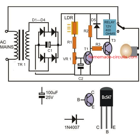
The transistors are rigged as inverters, meaning when T1 switches, T2 is switched OFF and vice versa.
The transistors T1 is wired as a comparator and consists of an LDR across its base and the positive supply via a preset.
The LDR is used for sensing the ambient light conditions and is used for triggering T1 when the light level crosses a particular set threshold. This threshold is set by the preset VR1.
The use of two transistors particularly helps to reduce the hysteresis of the circuit which would have otherwise affected the circuit if only a single transistor would have been incorporated.
When T1 conducts, T2 is switched OFF ans so is the relay and the connected load or the light.
The opposite happens when the light over the LDR falls or when darkness sets in.
Parts List:
- R1, R2, R3 = 4k7 1/4 watt
- VR1 = 10k preset
- LDR = any small LDR with around 10k to 50k resistance in day light (under shade)
- C1 = 470uF/25V
- C2 = 10uF/25V
- All diodes = 1N4007
- T1, T2 = BC547
- Relay = 12V, 400 ohms, 5 amp
- Transformer = 0-12V/500mA or 1 amp
2) Light Activated Day Dark Switch using CMOS NAND gates and NOT Gates
The second and the third figure incorporates CMOS ICs for executing the above functions and the concept remains rather similar. The first circuit out of the two utilizes the IC 4093 which is quad two-input NAND gate IC.
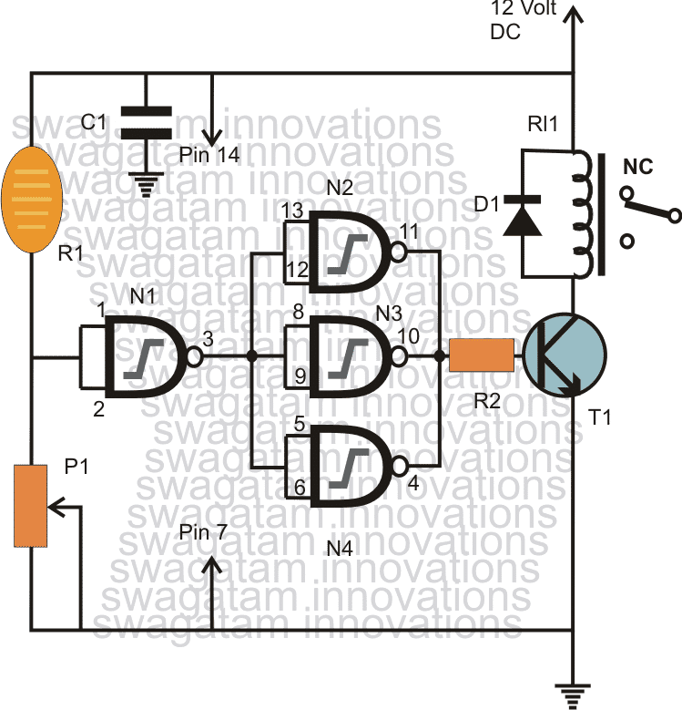
Each of the gates are formed into inverters by shorting its both the inputs together, so that the input logic level of the gates now get effectively reversed at thie outputs.
Though a single NAND gate would be enough for implementing the actions, three gates have been engaged as buffers for getting better results and in a view of utilizing all of them as in any case three of them would be left idle.
The gate which is responsible for the sensing can be seen accompanied with the light sensing device LDR wired across its input and the positive via a variable resistor.
This variable resistor is used for setting the triggering point of the gate when the light falling over the LDR reaches the desired specified intensity.
As this happens, the gate input goes high, the output consequently becomes low making the outputs of the buffer gates high. The result is the triggering of the transistor and the relay assembly. The connected load over the relay now flips into the intended actions.
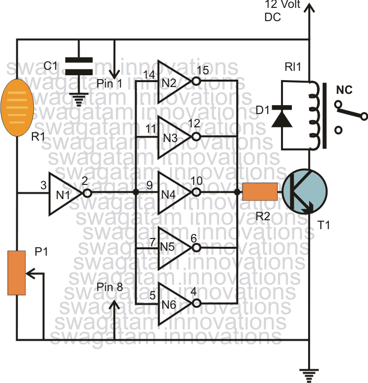
The above actions are exactly replicated using the IC 4049 which is also wired with similar configuration and is quite explanatory.
Parts List
- R1 = Any LDR with resistance of around 10k to 50k in day light (under shade)
- P1 = 1M preset
- C1 = 0.1uF ceramic disc
- R2 = 10k 1/4 watt
- T1 = BC547
- D1 = 1N4007
- Relay = 12V, 400 ohm 5 amp
- ICs = IC 4093 as in the first example or IC 4049 as in the second example
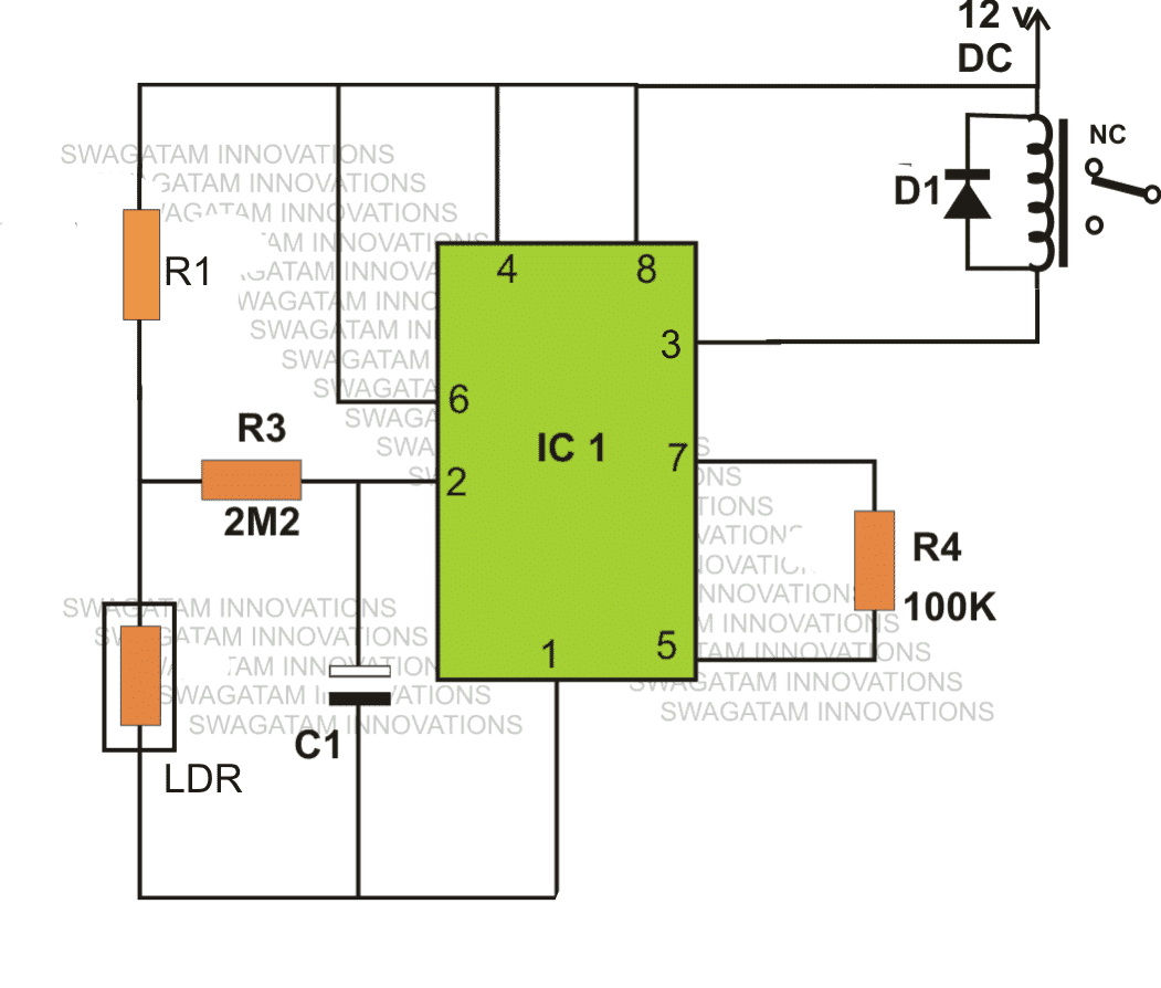
3) Light Activated Relay Switch using IC 555
The last figure illustrates how the IC 555 may be configured for executing the above responses.
Video Clip demonstrating the practical operation of the above IC555 based day night automatic lamp circuit
Parts List
- R1 = 100k
- R3 = 2m2
- C1 = 0.1uF
- Rl1 = 12V, SPDT,
- D1 = 1N4007,
- N1----N6 = IC 4049
- N1----N4 = IC 4093 IC1 = 555
4) Automatic Night Operated LED Lamp Circuit
This fourth circuit is not only simple but very interesting and very easy to build. You might have seen the new flashlights manufactured with new high bright high efficiency LEDs.
The idea is to achieve something similar but with an added feature.
Functioning Details
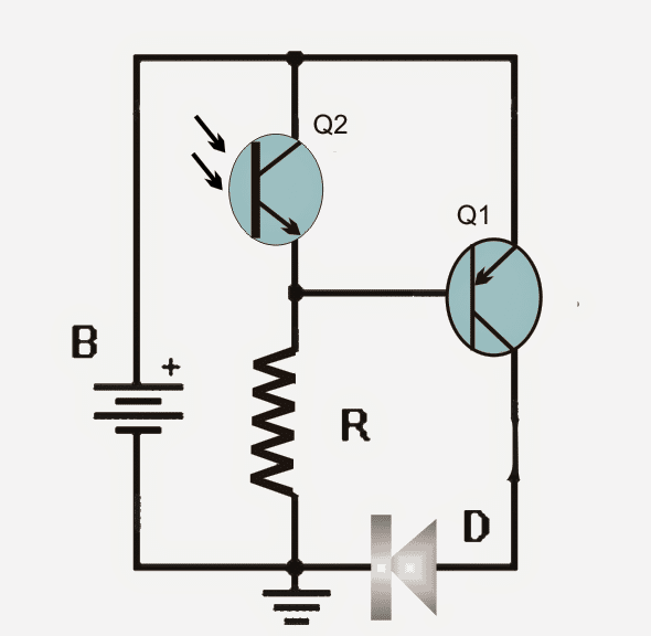
To make our circuit operative after dark, a phototransistor is employed, so that when the daylight is void, the LED gets switched ON.
To make the circuit extermely compact one button battery type is preferred here, quite akin to those used in calculators, watches, etc.
Understanding the diagram:
As long as ambient light illuminates the phototransistor, the voltage at its emitter lead is sufficiently high for the base of PNP transistor Q1 to keep it shut off.
However when darkness sets in, the phototransistor starts losing conduction and the voltage at its emitter diminishes causing the phototransistor to slowly switch OFF.
This prompts Q1 to begin getting the biasing via its base/ground resistor R and it starts to illuminate brightly as darkness gets deeper.
In order to control the level of the ambient light for which the LED may be desired to be switched ON, he resistor R values may be varied until the desired level is satisfied. Putting a potentiometer may not be recommneded, just to ensure a compact and sleek dimension of the unit.
The circuit may consume approximately 13 mA when the LED is illuminated and just a few hundred uA when its switched OFF.
Circuit Operation
Bill of material for the discussed automatic night operated LED lamp.
- 1 PNP BC557A
- One compatible phototransistor
- 1 super bright white LED
- 1 battery 3V coin
- One 1K resistor
PHOTO-ELECTRIC RELAY
You can find lots of applications in which photoelectric detection is employed to turn a circuit on/off. This below shown straightforward circuit is configured like a bistable multivibrator.
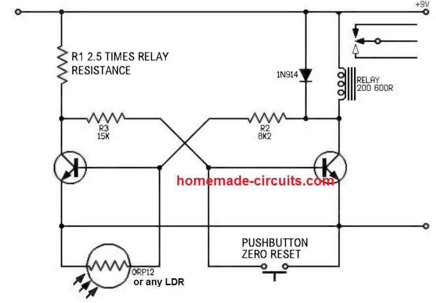
The Q1 base resistor is actually a photo-resistor with the number ORP12. In the absence of light, the resistance of the photo-resistor is high, this causes Q1 to conduct and Q2 is remains shut off. As the incident light on the photo-resistor OPR12 increases, its resistance falls to a point, until Q1 switches OFF and Q2 switches ON hard, activating the relay coil.In order to reset the circuit we can use the given push-button.
The freewheeling diode connected across the relay coil is to protect the transistor from relay coil reverse EMF spikes, and this diode could be any silicon diode such as the 1N4148 or 1N41007.
Automatic Light Sensitive Switch with Adjustable Dawn or Dusk Switching
This automatic ON/OFF light switch features a selector switch which facilitates the lamp (load) either to switch ON during night and switch OFF during day, or the opposite, that is switch ON during day and switch off at night or in darkness.
In other words the circuit can be used like a day activated automatic switch or a darkness activated automatic switch, depending upon the user preference or the specific application need.
The selection can be implemented simply with a flick of a DPDT switch.
WARNING: The circuit is not isolated from the AC mains supply and will be floating at the mains level, which can be fatal for anybody who touches the circuit in powered ON condition, without an insulated enclosure.
Circuit Description
- Parts List
- All resistors are 1/4 watt 5% CFR, unless, otherwise specified.
- R1 = 100K 1 watt
- R2, R3 = 100K
- R4 = 4.7K
- R5 = 220K
- R6 = 470K
- R7 = 68K
- R8 = 33K
- R9 = Any standard LDR
- P1 = 100K preset or trimpot
- Capacitor
- C1 = 100uF/25V Electrolytic
- Semiconductors
- D1 ----- D4 = 1N5408
- D5 = 10V 400 milliwatt zener diode
- T1 = BC547 Transistor
- Th1 = SCR C106
- IC1 = IC 741
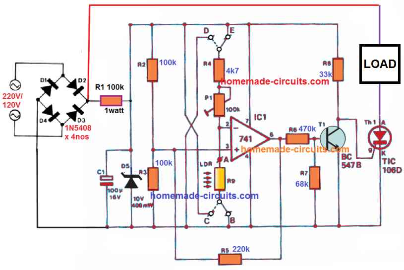
Referring to the schematic above, the working of this dual function light activated switch can be understood with the following points:
The op amp 741 forms the heart of the circuit and is wired as a comparator.
Its non-inverting input pin#3 is clamped with a fix reference derived from the junction of the resistive divider formed by R2/R3.
R2, R3 being equal in value, the reference voltage is set at the 50% of the zener voltage D5 which is used for stabilizing the rectified 310 VDC to 10 V DC.
The input DC power is supplied directly from the AC mains via a bridge rectifier set up, while the rectified DC high current is dropped through R1 to suit the attached electronic circuitry.
Now, the non-inverting pin of the op amp being fixed at around 5 V reference, the inverting input pin#2 is used for the detection of the light level via another resistive network formed by R1/P1 and the LDR.
Using as Light Activated Switch
Since the pin#3 is fixed at 5 V, means, as long as the pin#2 remains below this reference level, the op amp output remains high, enabling the T1 to remain switched ON, and the SCR/load switched OFF.
This situation takes place when the R4 end is connected with the positive line, and the LDR is connected at point B which is the ground line, and illuminated by day light.
This is because, during day time the LDR resistance drops drastically causing the pin#2 potential to drop significantly and below pin#3 potential.
So with the selector switch contacts connected across points E and B, the light sensitive switch works like an automatic light activated switch.
Using as Night or Darkness Activated Switch
In order to flip the response, and enable the light sensitive switch to work like a darkness or night activated switch, we just have to toggle the selector switch such that the relevant contacts connect the points D with the positive line, and point C with the negative line.
Once this is implemented, the LDR now gets associated with the positive line, and the R4 end gets connected with the negative line.
In this situation, if the LDR is sufficiently illuminated, causes its resistance to drop, which in turn causes the pin#2 potential to rise over the pin#3 reference level. This instantly causes the op amp output pin#6 to go logic zero, and switch OFF the BJT driver.
With the BJT turned OFF, the SCR and the load are also turned OFF in the presence of day light on the LDR.
Next, when darkness sets in, the LDR resistance increases sufficiently, causing the pin#2 potential to drop below the pin#3 potential, switching ON the BJT, the SCR, and the load, during the night time.
The circuit is now transformed into a darkness activated switch for the load or the connected lamp.
Therefore, just by flipping the selector switch connections across the B-C and D-E points, the light sensitive switch can be quickly pushed into the desired modes, either as an automatic light activated or darkness activated switch.
Hysteresis Function
Resistor R5 introduces some level of hysteresis to the op amp response so that the output of the op amp does behave erratically during the twilight or the transition periods where the light level on the LDR is at the threshold points.
The R5 ensures that the op amp output switches ON or OFF firmly, only once the light level has convincingly crossed the switching threshold.
please I have struggled but failed to get 100k ohms reliable resistor or trimpot to fix in the diagram you sent me for turning on the 12v dc bulbs, is there any idea we can join resistors to fix that
Sorry, without the 100k preset it is not possible to adjust the tripping point of the transistor and the lamps…not possible with fixed resistors….
so how many tip122 is needed and please design the circuit
I have already designed and provided you the circuit .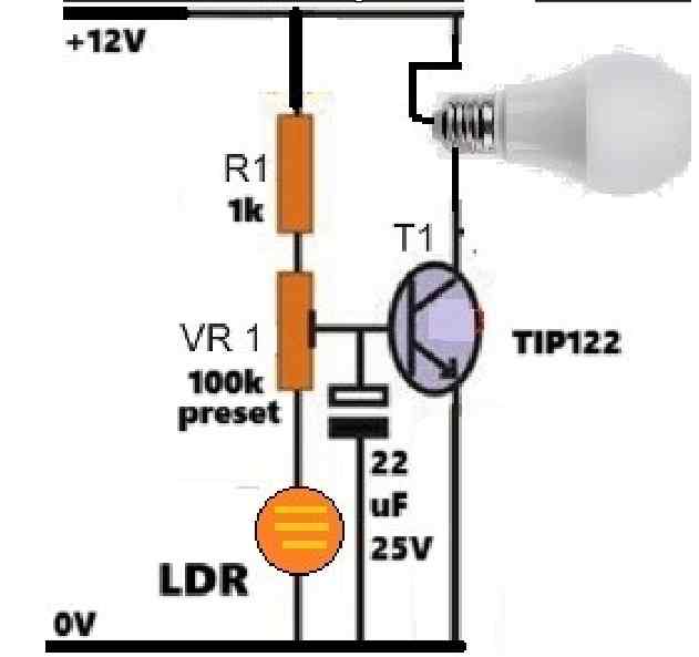
" rel="ugc">
For each room you can wire separate bulbs between the +12V and the TIP122 collector individually.
so I will just have to add the bulbs from the positive connecting them in series while adding the tip122, please just help with an illustration diagram
You have two terminals for each bulb, right? So connect the positive termina of the bulb with +12V of battery and the negative terminals with the collector of the TIP122.
Just make sure the total current of the LED bulbs does not go beyond 2 amps, that means you can connect a maximum of 24 watt of bulbs…
no, not in series…connect in parallel…
the 12v dc bulbs, for example very many bulbs that can light every room in a house for anyway let’s say the 10 bulbs to provide light solar in every room and 2 bulbs for outside, you know the LED 12v dc bulbs always sold in shops like 1w(12vdc) ,2w(12vdc), 3w(12vdc) etc… however much the dc bulbs and their consumption could be as long as the power consumption of 12vdc bulbs will depend on the battery ah, let’s just make a simple unique switch so I can make and sell to people
In that case the transistor will need to be a TIP122, a BC547 will not take the load of those 12V bulbs…
ok I was saying that I wanted to try first the diagram of bc547 since Im having very many pieces of bc547 because it’s becoming a little bit hard to get tip122, please try to make it for me because I wanted to use it with a battery 12v powering 12v bulbs
What type of 12V bulb do you want to use?
I want to try the one of 2 bc547 but I want to remove the transformer and use it direct from the DC 12v battery for lighting DC 12v bulbs any changes to be made in the circuit?
You can try the following circuit:
" rel="ugc">
please edit the diagram of the 555 ic please design it to let full 12v to pass through because it’s not letting it through, please you know the relays I’m having are 700 ohms plus so just help me because want to make the automatic 12v dc automatic switch to sell at least to earn a living please I’m just begging
IC 555 will always pass the full VCC supply voltage through its pin#3, so the diagram is OK, I think your IC 555 could be faulty, or there may be some other problem…
maybe because you added 1k resistor the way you were showing in the video but I did mine in the diagram way wi a 1 wat DC bulb and has refused completely, is it because I’m using 5mm ldr, and do ldr die? when I joined number 3 from the 555 ic to the coil and I think its negative, when I connect the way you sent me yesterday the bulb goes direct on, when I connect the number 3 from 555 that is connected to the coil, when I join it to negative the relay switches off the dc 1w bulb
In the video the 1k is used for the LED. You can check the resistance of the LDR with different light intensities and check whether the LDR resistance is changing or not between 10k and infinity (many meg ohms).
I’ve tried the 555 ic diagram and it’s not working, the relay I have is a 6 pin 12v relay, of Which in your diagram you indicated ic pin 8 to the relay coil left and it’s possitive terminal connected to it and ic pin 3 to the right terminal of the relay and it was connected to negative input, please help me because I’ve bought very many relay’s and very many ldr to do this project, since you know the 6 pin type of relay I have, please help me edit that diagram and show me the real pin out of the relay. thank you
The 555 circuit is a tested circuit, you can check out the video, so it has to work.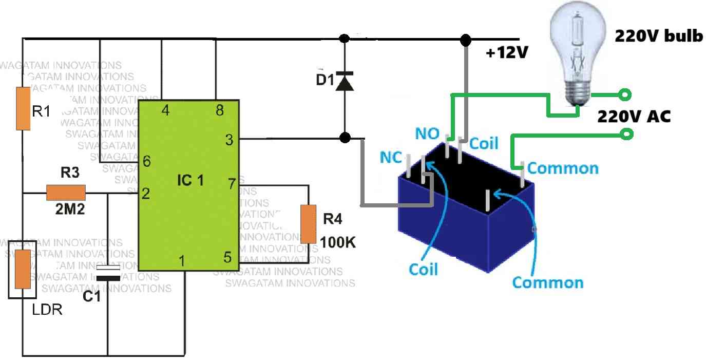
For 6 pin relay connection, you can refer to the following diagram:
" rel="ugc">
I have the 0.01 uf capacitor I have them, let me make the circuit then will update you
in the circuit of 555 ic you had put at the partlist a capacitor 0.01uf can I use 10uf capacitor 50v because it’s becoming very hard for me to get 0.01uf
For C1 in the 555 circuit, you can use a maximum of 1uF…
please send me the full diagram of 555 ic automatic simple day night switch. that diagram in the video please. thank you
The diagram is already given just above the video, in the above article.
do you remember the diagram you sent me some few days ago for turning on the AC bulbs never had a relay because I told you about how the up diagram was a little bit confusing (d,e,c,b), so please help me edit the other very diagram you sent to me some few days ago and let it do the opposite the way we want
You can try the following circuits: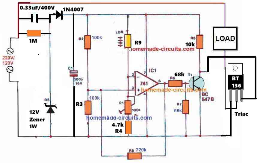
" rel="ugc">
This circuit is not isolated from AC mains and therefore it is extremely dangerous to touch in switched ON condition…
now I want you to make it do the opposite by switching the load at day time and switch it off at night
Please select the circuit which you want to use from the above article, and then just configure the relay NO or the NC contacts that will switch ON the load during day time.
no please just forget about DC or DC bulbs issues,
just make an automatic switch to always turn on AC bulbs or AC florescent lights in the morning and switch them off in the evening to save electricity bills not to allow AC bulbs or AC florescent lights to be used at night ? is it possible?
It is already given in the above article. All the above circuits are designed to do exactly that. But they will switch ON the load during evening and switch OFF during daytime…
the problem with the circuit you have sent is the transformer has already changed the AC power to DC, please try understand me and create a circuit that will allow AC mains getting switched to AC bulbs, where by the AC bulbs shall stay on only at day time
(Note here we’re using AC bulbs only) so just create a switch that will switch AC mains to AC bulbs and the switch shall be on only at day time
It is very confusing, in the earlier comment you said you want to illuminate DC 12V LEDs, that’s why I suggested you the above diagram.
If you want to switch AC load, then you can use any of the above designs with relay or with triac. All the above designs are suitable for AC 220V or 120 V AC inputs, and loads.
okay now the switch I want you to design is to keep the AC 220v on at day time only when the night begins it switches off, please use LDR and relay thank you just design only that switch it’s what I want because I’ve now understood what I want thank you
no this is circuit I want you to make is to save electricity bills at home by enforcing the use of AC 220v lights or bulbs only at day time, when the night begins AC 220v shall be switched off and DC 12v from the battery shall be allowed to pass through the circuit thus switching on the DC 12v bulbs.
just imagine like you have AC 220v bulbs wired alone and DC 12v bulbs wired alone so the switch you are going to design shall always turn on AC 220v flow to it’s bulbs only at day time when the night begins the switch shall automatically turn off all the AC 220v bulbs and turn on the DC 12v bulbs. thank you
Ok, then you can try the following circuit: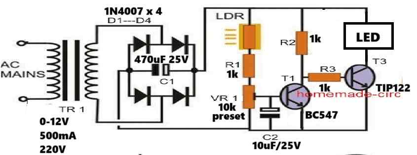
" rel="ugc">
ok I can not count the bulbs because I want to try to make this circuit and sell it to people that is why I was trying to say that let it be just allowing DC 12v to flow to the direction of bulbs however much the number bulbs as or the wattage, so we can make the circuit switch at least to work with batteries of 40ah to 100ah batteries, but as a circuit designer you can also help with the knowledge because I don’t know much because we would put a minimum current to flow to be like this and maximum current to flow is DC 12v but I don’t know much because me I know the type of relay I ordered of 12v please let the battery strength or ah also determine as long as maximum DC voltage to flow is DC 12v
Do you want a solar street lamp or an automatic day/night lamp? Solar street lamp will use battery, automatic day/night lamp switch will not need a battery, it can work with 220V AC mains input.
please I request you to design a circuit that will always allow AC 220v flow to appliances or bulbs at day time but when it reaches at night automatically it switches to turn on the DC 12v flow to DC 12v bulbs, but in case of AC 220v power outage at day time the DC 12v should still abide by the law of staying off till at night then the DC 12v can flow again please try to help me please (please let’s try to use LDR) thank you
Please provide DC 12V LED voltage and current ratings….and how many you want to use…?
please for sure it’s becoming very hard for me to get Tic106d, is there anything we can use besides tic106d ?
You should be able to get this SCR easily anywhere:
https://www.littelfuse.com/media?resourcetype=datasheets&itemid=04b0ee36-633f-4fd9-b07e-05060d2e62fb&filename=littelfuse-thyristor-c106-d-datasheet
If not then you can search for any other SCR suitable for 220V AC inputs.
please swagatam the last circuit diagram seems a little bit confusing to new learners since there is day switch, then night switch, I was requesting you to please make a circuit similar to that one that will only switch ac bulbs at night only, please try to design it to be very simple and minus the use of a transformer. thank you please
Hi Rashid,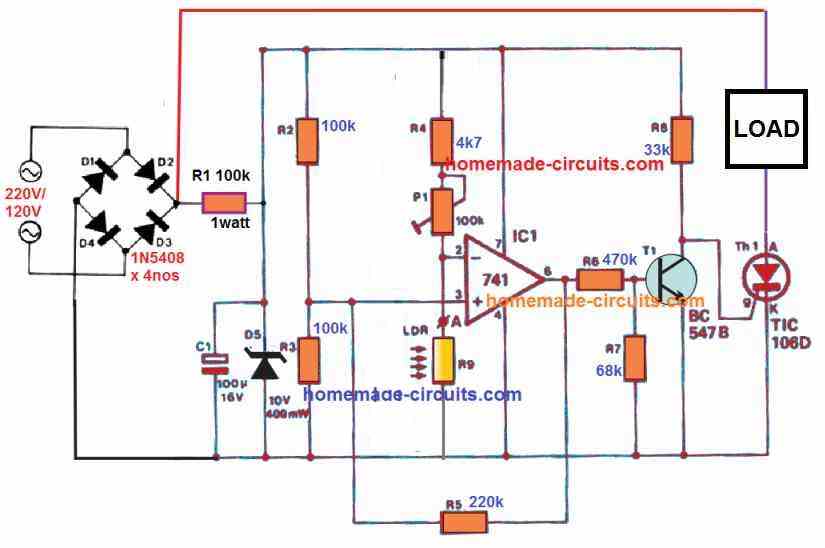
In the last circuit, the switch can be toggled to select the dark activated mode or the day activated mode. If you want a darkness activated switch, the in you can modify it in this way:
" rel="ugc">
design and connect a low voltage 220/12v lighting circuit. the connecting sequence will consist of wiring up two,220v lamp via a daylight switch which also activates the timer that connect the second lamp of fluorescent light.
Swagatam,
Instead of c1 0.1 ceramic disk can I use 0.22uf?
0.22uF will also work, make sure to connect it directly across the pin1 and pin8 of the IC or directly across the supply pins of the IC.
Hello swagatam,
Day night sensor light using ic 4049 and transistor bc 547 please tell me connection of emitter collector means where is connected voltage and ground
Hello Sharan,
The emitter of the transistor is connected to the ground supply or the 0V supply, collector is connected to the relay coil. Pin number 1 of the IC 4049 will go to the positive supply, and pin 8 of the IC will go to the ground supply.
I have equalized all the connections as you said, but the circuit is not working. Only relay is working.
The 4049 is a very simple circuit and should work, check all IC connections.
Please tell me ic 4049 pins 1-16 voltage
Short circuit the LDR points, then pin2 should become 0V, and the all 4049 gates connected to R2 should become high or 12V. The opposite should happen when the LDR is removed or pin 3 is disconnected from the positive supply.
In the first circuit:
The LDR is used for sensing the ambient light conditions and is used for triggering T1 when the light level crosses a particular set threshold. This threshold is set by the preset P1.
WHAT P1? NO P1 IS SHOWN!
Thanks for pointing out the mistake. P1 is actually the variable resistor VR1. I will correct the mistake soon.
What is the parts list for the
Automatic Light Sensitive Switch with Adjustable Dawn or Dusk Switching.
I am unable to see the diagram clearly
I have added the parts list under the specified circuit diagram.
Good day.
I have a tropical fish tank which has a 220v L.E.D UV light installed. I am running it on a timer at the moment.
Is there a possibility to have a day & night switch that only switches on during daytime ??
Regards
Leon
Yes that’s possible. You can try the first circuit from the following article. Make sure to connect the bulb to N/O contact of the relay instead of N/C .
https://www.homemade-circuits.com/3-simple-automatic-street-light-circuits-explored/
Hello Swag,
Long time since the last time I writte to you ! How are you?
Swag, I need your help to have a similar circuit as those showed here, but I like to use the system for LED’s (in DC then). So I do not need the AC transformer.
I’m sure you have a drawing for that,but I’m not able to find it in your numerous circuit.
Thanks in advance
Claude
Claude
Hello Papaciela, for switching LEDs directly with a DC source you will have just remove the relay, and put LEDs in its place. The configuration of the LEDs and the driver transistor rating will depend on the specifications of the LED.
Dear Mr. Swagatam,
I am a retired senior citizen, an ex – Government employee. Though a Registerd Medical Practitioner, at present I am spending my time to design an equipment to do ‘ Non invasive knee repairs. ‘ It is almost in the final stages. My equipment is intended to produce synovial fluid. One of the reasons for knee pain in elderly people is insufficient synovial fluid.
When I was searching for a simple oscillator circuit, I came across your website. I have gone through some of your circuits and explanations.
You are doing a great work in teaching practical electronics, simple and beautiful. Hats off. Please keep it up.
With love and regards
Dr. Luke Thomas
Hello Swagatam,
In the above circuit 4) Automatic Night Operated LED Lamp Circuit, please could you explain to me why the Q1 emitter is connected to positive and the collector to the load and ground. All of the PNP circuits I have built so far have the collector to +V and the emitter and load to ground.
Thanks in advance.
Hello Paul, the emitter of PNP is always with reference to the positive line, and its collector is always towards the negative or the ground line, and for NPN the emitter is always with reference to the ground or 0V line.
PNP collector can never be associated with the positive line, that can never work.
Hello Swagatam and thanks for the quick reply.
I’m still confused as what you say is how I understood PNP transistors to work but digging deeper into this, I’ve found several articles which suggest that the arrangement where the collector is connected to V+ and the emitter to load and ground does work although with a greatly reduced gain factor, and I have constructed your circuit with the c and e connected in both directions with success. Odd!
Hello Paul,
there’s no way you can make a PNP conduct by connecting its emitter with the negative line, and collector load with the positive line. It is like trying to use a diode by applying positive to its cathode and the load to its anode and negative line.
Hello Swagatam
Rest assured I can prove this – I will send you a video if you wish. Please consider my earlier comment about loss of gain – this is documented here: https://electronics.stackexchange.com/questions/29756/bjt-in-reverse-active-mode-of-operation
I appreciate this document is for a NPN but the same applies for a PNP.
Thanks
Hello Paul, No matter what anybody says, it’s no point discussing something which unnatural, abnormal and nontechnical. In electronics I will believe and follow only those concepts which makes sense and is recommended by the researcher and the manufacturer.
Hello Mr. Swag , I use the 555 circuit and work fine can it be supplied with a transformerless power supply ? in this post https://www.homemade-circuits.com/cheap-yet-useful-transformerless-power/
Sorry my english is not good
Hell Sarwana, yes that may be possible. You can try the first transformerless power supply design, but make sure to change the 50 ohm resistor to 5 ohms resistor, and use a 5 watt zener instead of 1 watt.
I want to use it for providing light for 12-16 hrs per day requirement.
Hen actually needs 12-16 hrs of light for cycle that need for egg laying. During winters daylight is shorter and as sun set it will automatically switch on the light and switch it on till 12-16 hrs of total light (including natural sun light + artificial light) have been completed.
In project number 1 (with transformer), why using R3? What if only using R2 (R3 removed)?
You can remove R3, it will still work
Hello sir Swag, can this light sensor circuit respond to my neighbour’s light bulb source.
Hello Seun, yes definitely, if the light source is bright enough, to prevent this you should put the LDR inside a pipe like enclosure so that it sees only the ambient light and no other artificial light
Thank you Mr SWAGATAM for your fast replay and for the added listing of parts. So
while I was thinking about the execution of the project N°2, I have got the Idea to ask you what can we add to the diagram to get the special lights remote controled instead of its dependance to the day light, I mean to switch between ON and OFF at any time with a remote controle device, any one, of course something simple.
Salutations.
Hello Rabah, Remote control is possible by integrating any preferred remote control circuit output with the relay driver stage.
You can find many remote circuits here:
https://www.homemade-circuits.com/?s=remote+control+simple
Good day sir swag? I’m here again and I need your help in regarding to 220v automatic street light by using of BT136/ BT138. Sir base on the project that I see in YOUTUBE. What do you think about the BT 136/ 138, this can work for 220v to ON n OFF the led bulb? Thank you
Hi Rav, yes it should work but you must connect a triac correctly as indicated in the following example:
Hello sir swag, actually the circuit that I see is only 3 pcs parts or 4. A bt 136, resistor, and ldr which is connected to direct 220v. The ldr connected to T1 and Gate. While the bulb connected to T1 and T2. It is possible to switch on the bt136 in dark place/night? Thank you
Hi Rav, you can try the following configuration, it should work.
It was designed by Mr. D MohanKumar
Thank you very much sir swag for your always free of time to answer my query. After I test this circuit you give, I’ll give you the feedback for the result of my test. Thank you again sir.
No Problem Rav, wish you all the best!
Hi Swag,
A bad manip…. Here again my question:
Can I change R3 by a variable resistor or potentiometer if I want to use different light ambient intensity to adjust the threshold that will activate the relay. What would be the range value of this component to obtain this.
Thank’s and regards
Hi Papa Ciela, thanks for posting your question again! If you are referring to the IC 555 circuit, you can replace R1 with a 1M pot for getting the required adjustments.
R3 and C1 are placed for implementing a slight delay in the operation, so that the relay does not vibrate during twilight transitions.
Hi Swag,
You answer at the light speed !!!
Thank you so much !!
You are welcome Claude!
lease the pin 7 and 5 connected with a resistor are not taken to ground and the pin 1 again can i use preset in place of one connected to pin 2 thanks
pin7 and 5 should be exactly as shown, they shouldn't be grounded.
Pin#1 line is the negative supply line.
1M preset can be used with pin#2
Hello,
Can you tell for the first diagram what are R1, R2, R3 and VR1 values?
Thank you
BR
you can refer to this article for more info:
https://www.homemade-circuits.com/2011/12/super-simple-light-activated-switch.html
can you help me how to make LDR opposite ? in a way that when the loght come through the LDR the electricity cant flow or turn off and when the LDR sense dark the electricity can flow or turn on…?
in the above shown diagrams, you just need to change the position of the lDR from the upper arm of the preset to the lower arm of the preset or vice versa for getting the desired results
Hello swagatam
I know what is LDR function but I don't know how to buy it and what is its name in the market.
Can you please sho me its name in the market.
Thank you
Hello Sasa,
It's called LDR everywhere, even the shopkeeper will know this and identify this component as LDR only, so you can tell him this name.
@Swagatam Majumdar what is the value of resistor and the variable (potentiometer) in figure no.1 please help my for my project to be submit in monday please
Please check the following link for the details:
https://www.homemade-circuits.com/2011/12/super-simple-light-activated-switch.html
hi can you elaborate please cant understand your reply..for LDR
make the last 555 circuit given in the above article, interchange R1 and the LDR positions, remove the relay and use the positive supply coming out from its pin3 to power the flasher circuit meaning the flasher circuit's positive line will get powered from the above circuits pin3 and NOT from any external 12V source. This configuration will shut off the LEDs during day and vice versa.
Please am constructing same automatic street light system using 555 timer circuit as my final year project work in school
Please I need your help.
Please provide more details I will try to help!
Thanks but please after u are done send me the link to watch
I think the circuit is already given in the above article. Design no. 3)
Please am constructing automatic street light system using,
1 IC NE555 1
2 Bipolar Transistor BT136 1
3 Diodes 1N4007 4
4 Zener diode 12V 1W 1
5 LDR – 1
6 AC Lamp 230V 1
7 Variable Resistor 10K 1
8 Resistor 470Ω, 1M/1W 1, 1
9 Ceramic Capacitor 330nF, 0.01µF 1, 1
10 Electrolytic Capacitor 330 µF 1
11 AC Power Supply or AC adapter 220V 1
Please I need the pdf or knowledge about of same project work to do mine
Hi, I cannot provide the exact project with the exact parts details you have provided, however I can design it with my own knowledge and understanding.