Voltage spikes can sometimes be a big nuisance as far as the safety of the various electronic appliances are concerned. I have explained how to make a simple AC Mains surge protector circuits at home.
What is a Surge Protector
A surge protector is an electrical device which is designed to neutralize minor electrical spikes and transients that normally keep appearing in the mains utility lines.
These are normally installed in sensitive and vulnerable electronic equipment to prevent them from getting damaged due to these sudden unprecedented surges and voltage fluctuations.
They work by instantaneously short circuiting any excess high voltage that may appear in the mains AC line for a very duration.
This duration is usually lasts in microseconds. Anything above this period of time may cause the surge suppressor itself to burn or get damaged
What is Voltage In Rush
A sudden voltage spike is basically a sharp rise in the voltage lasting not more than a few milliseconds but enough to cause damage to our precious equipment almost instantly.
It thus becomes imperative to stop or block these from entering vulnerable electronic gadgets like our personal computers.
Commercial spike busters are though available pretty easily and cheaply too, cannot be trusted and moreover have no reliability test arrangement so it becomes just a "assuming" game, until it's all over.
Working Design
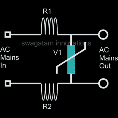
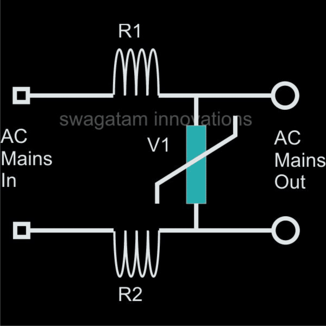
The circuit of a Simple AC Mains Surge Protector Device below, which shows how to make a simple homemade AC mains high current protector device is based on very simple principle of "speed breaking" the initial jolt through components who are well equipped in the field.
A simple iron resistor and MOV combination are more than enough to provide the protections we are looking for.
Here R1 and R2 are 5 turns of iron wire (0.2mm thick) over a 1 inch diameter air core each followed by an appropriately rated varistor or an MOV connected across them to become a full fledged spike protector system.
Sudden high AC entering the input of spike are effectively tackled and the "sting" absorbed in the course by the relevant parts and a safe and clean mains is allowed to go through the connected load.
Metal Oxide Varistor (MOV) Calculations and Formulas
The calculation of energy during application of such a pulse is given by the formula:
E = (Vpeak x I peak) x t2 x K
where:
Ipeak = peak current
Vpeak = voltage at peak current
β = given for I = ½ x Ipeak to Ipeak
K is a constant depending on t2, when t1 is 8 μs to 10 μs
A low value of β corresponds to a low value of Vpeak and then to a low value of E.
Transient Protector Using Inductors and MOV
Question Regarding Surge Prevention in Electronic Ballast
Hi swagtam, I found your email address from your blog. I really need yr help.
Actually my company has customer in china we make UV lamps and we use electronic ballast for it.
Now the problem is in china because of Over Voltage the ballast burn out so i design circuit which is in attachment which doesn't help either?
So I found your Ultimate High/Low Voltage Protector Circuit which i wants to build. or can you tell me the update if i can do in my circuit that will be great.
Solution
According to me the problem may not be with the voltage fluctuations, rather it's because of the sudden voltage surges that's blowing of your ballast circuit.
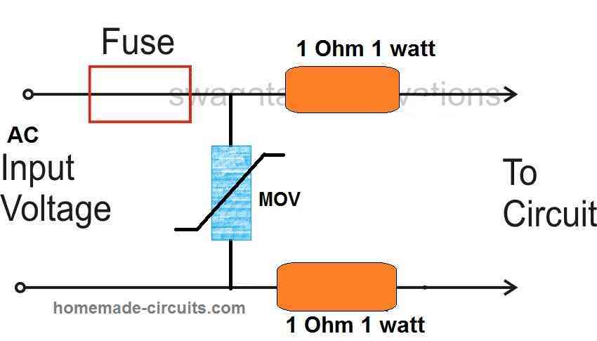
The diagram shown by you may not prove very effective, because it does not incorporate a resistor or any kind of barrier with the MOVs.
You may try the following circuit, introduce it at the entry point of the ballast circuit.
Hope it works:
Using an NTC and MOV
The following image shows how two different sudden high voltage suppressor devices could be tied up with the mains line for achieving a double edged safety.
The NTC here enables an initial switch ON current in rush protection by offering a higher resistance due to its initial lower temperature, but in the course of this action its temperature begins increasing and it begins allowing more current for the appliance until a normal working conditions achieved.
The MOV on the other hand complements the NTC output and makes sure that in case the NTC is unable to stop the up-surge onslaught correctly, it switches ON itself shorting the residual high transient content to ground and as a result establishing a safest possible supply for the connected load or the appliance.

Highly Recommended for you: 220 V AC Filter Circuit
Formulas for Calculating MOV and NTC Parameters
NTC (Negative Temperature Coefficient) Thermistor Formulas
Resistance-Temperature Relationship (NTC Thermistor)Using the Beta Parameter Equation:
R(T) = R0 * e(β * (1/T - 1/T0))
Where:
- R(T) = resistance at temperature T (in ohms, Ω)
- R0 = resistance at a reference temperature
- T0 (in ohms, Ω)
- β = material constant (in K)
- T = temperature in kelvins (K)
- T0 = reference temperature in kelvins (K), usually 298 K (25°C)
Using the Steinhart-Hart Equation (more accurate):
1/T = A + B * ln(R) + C * (ln(R))3
Where:
- T = temperature in kelvins (K)
- R = resistance at temperature T (in ohms, Ω)
- A, B, C = constants that depend on the specific thermistor.
Thermal Time Constant (NTC Thermistor)τ = (Cth * R) / P
Where:
- τ = thermal time constant (in seconds, s)
- Cth = thermal mass of the thermistor (in joules per degree Celsius, J/°C)
- R = resistance of the thermistor (in ohms, Ω)
- P = power dissipated by the thermistor (in watts, W)
Inrush Current Limiting (NTC Thermistor)I(t) = V / R(T(t))Where:
- I(t) = current at time t (in amperes, A)
- V = supply voltage (in volts, V)
- RT(t) = resistance of the thermistor at the temperature T(t) (in ohms, Ω)
Additional Formulas:
MOV:
Voltage-Resistance Relationship:
R(V) = (Vr2) / (V2 - Vr2) * Rmax
Energy Absorption:
E = 1/2 * C * Vmax2
Clamping Voltage:
Vclamp = Vr * (I / Irated)α
NTC Thermistor:
Beta Parameter Equation:
R(T) = R0 * e(β * (1/T - 1/T0))
Steinhart-Hart Equation:
1/T = A + B * ln(R) + C * (ln(R))3
Thermal Time Constant:
τ = (C_th * R) / P
Inrush Current Limiting:
I(t) = V / R(T(t))
RFI Line Filter and Surge Suppression Circuit
If you are looking for a mains AC line filter circuit having a combined protection against radio frequency interference (RFI) suppression, along with voltage surge control, then the following design could prove quite handy.
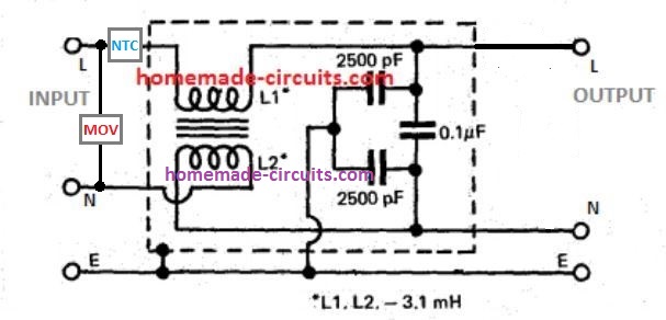
As we can see, the input side is protected with an NTC and MOV. The MOV grounds any instantaneous over voltage surge, while the NTC limits an over current surge.
The next stage constitutes an RFI line filter, comprising of a small ferrite transformer and a few capacitors.
The transformer arrests and blocks the passage of any incoming or outgoing RFI across the line, while the capacitor network reinforces the effect by grounding the residual high frequency content across the line.
The transformer is built over a small ferrite rod, having two identical winding wrapped one over the other, and one of the winding end connections swapped between the input/output Neutral line.