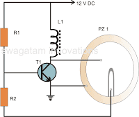
In this article I have explained how to make a very simple circuit for buzzer using piezo electric transducer, two resistors, a small coil and a BC547 transistor.
A buzzer is a high frequency oscillator circuit used for generating a buzzing sound through a transducer or speaker output.
Simple Buzzer using a Single Transistor
Just a single transistor, a ferrite inductor, and a piezo transducer, that's all you will need to make this circuit “buzz” or rather “twit” for you, with an output that may be quite loud and ear piercing.
The simple piezo buzzer circuit described here actually works in a quite unique way. Instead of the normal working concept employed by other forms of oscillators which require resistor and capacitor networks for generating the oscillations, this circuit use inductive feedback for the required operations.
Circuit Description
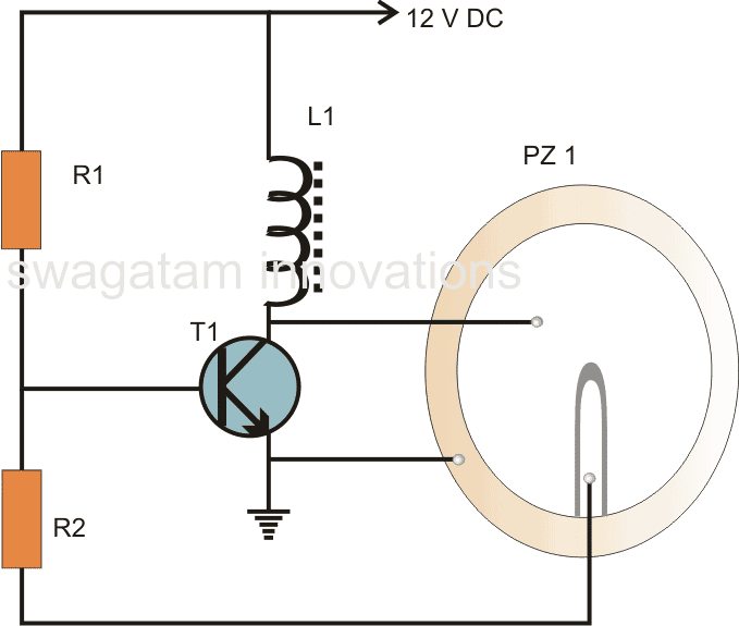
Referring to the above buzzer circuit diagram we find that the transistor T1 along with the inductor forms the heart of the circuit.
Basically the coil which is specifically called the buzzer coil, is in fact positioned for amplifying the created oscillations while the actual feed back is provided by the center tap of the three terminal piezo element used for the present application.
When a voltage is introduced in the circuit, the transistor conducts, operating the piezo element across the buzzer coil.
However this also leads to the grounding of the base of the transistor through the center tap of the piezo element, this instantly switches off the transistor and in turn the piezo also switches off, releasing the base of the transistor.
The transistor reverts to its original state and the cycle repeats, generating oscillations or the required “buzzing” frequency.
The center tap from the piezo transducer plays an important role in sustaining the oscillations and therefore in this particular design we need a three terminal piezo rather than a two terminal one.
The oscillations produced at the collector of the transistor is dumped into the coil, saturating the coil with magnetic inductions.
The coil kicks back the stored energy during the oscillations, magnifying the generated AC across it.
This stepped up AC is applied across the anode and the cathode of the piezo element, which starts vibrating sharply according the pitch of the frequency, generating a shrill, ear piercing sound in the air.
However to make the sound audible at maximum intensity, the piezo transducer needs to be glued or installed in a special way inside its housing.
Video Clip
How to Stick Piezo
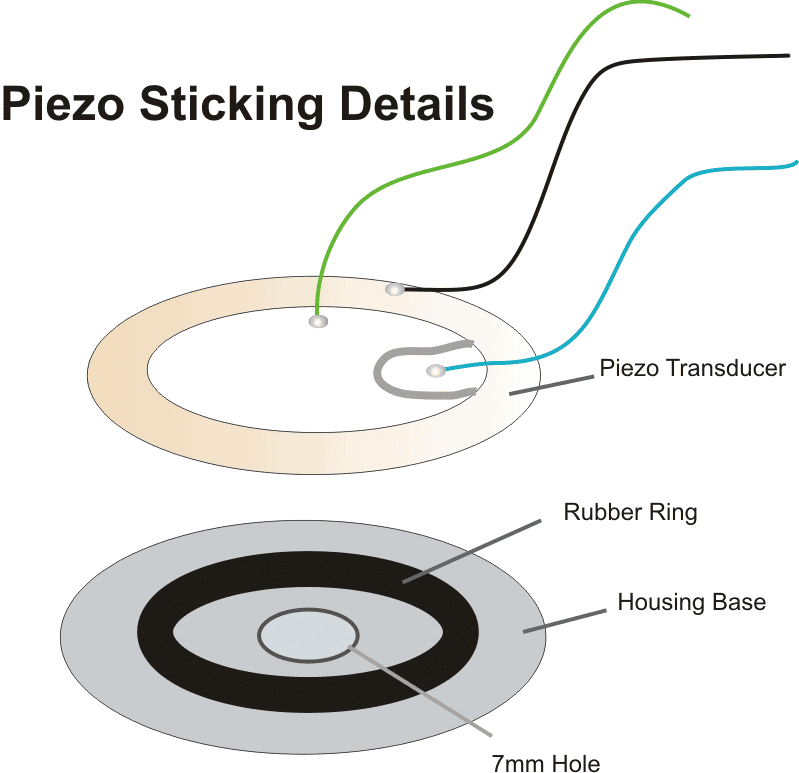
Video Clip showing the various procedures required for sticking a piezo transducer correctly:
For this particular application the piezo element needs to be stuck at the base of its housing which must consist of a hole having a diameter of about 7 mm.
The piezo element cannot be stuck directly over the base of the housing, rather it must stuck and positioned over a soft, pure rubber ring, having diameter 30 % less than that of the piezo transducer.
Only if the above fixing procedure is followed, the buzzer will sound, otherwise the sound may get choked and fail to reproduce.
Parts List
- R1 = 100K,
- R2 = 4k7,
- T1 = BC547,
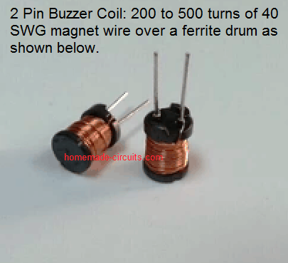
- L1 = Buzzer inductor,
- PZ1 = Piezo element, 27mm, three terminal
- Rubber ring = 22mm
Formulas and Calculations
Transistor Operating Conditions
Base Current (IB):
IB = (Vin - VBE) / RB
Where:
- Vin = Input supply voltage
- VBE = Base-emitter voltage of the transistor (typically ~0.7V for BC547)
- RB = Base resistor value
Collector Current (IC):
IC = β * IB
Where:
- IC = Collector current
- β = Current gain of the transistor (typically ~100–200 for BC547)
Saturation Condition:
IB > IC / β
Inductive Reactance
Inductive Reactance (XL):
XL = 2 * π * f * L
Where:
- XL = Inductive reactance (in ohms)
- f = Oscillator frequency (in Hz)
- L = Inductance of the coil (in henries)
Piezo Capacitance and Impedance
Capacitive Reactance (XC):
XC = 1 / (2 * π * f * Cs)
Where:
- XC = Capacitive reactance (in ohms)
- f = Oscillator frequency (in Hz)
- Cs = Capacitance of the piezo (in farads)
Combined Impedance (Z):
Z = √((XL - XC)2 + R2)
Where:
- Z = Total impedance (in ohms)
- R = Equivalent resistance of the circuit (in ohms)
Power Delivered to the Piezo
Power (P):
P = VAC2 / Z
Where:
- P = Power delivered to the piezo (in watts)
- VAC = AC voltage across the piezo (in volts)
- Z = Impedance of the piezo (in ohms)
Energy in the Inductor
Energy (E):
E = 0.5 * L * I2
Where:
- E = Energy stored in the inductor (in joules)
- L = Inductance of the coil (in henries)
- I = Current through the inductor (in amperes)
Oscillation Frequency
Frequency (f):
f = 1 / (2 * π * √(Ltotal * Ctotal))
Where:
- f = Oscillation frequency (in Hz)
- Ltotal = Total inductance (internal + external) (in henries)
- Ctotal = Total capacitance (internal + external) (in farads)
Voltage Gain of the Oscillator
Voltage Gain (Av):
Av = XL / Z
Where:
- Av = Voltage gain (unitless)
- XL = Inductive reactance (in ohms)
- Z = Total impedance (in ohms)
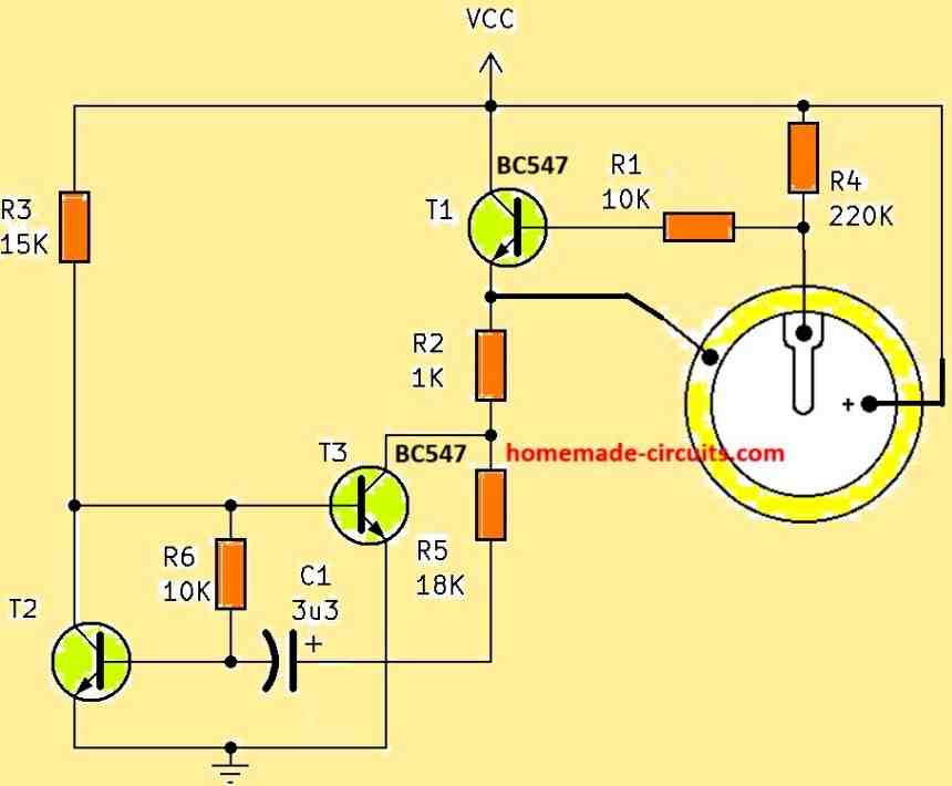
Intermittent Piezo Buzzer Circuit using Transistors
If you are looking for an intermittent piezo buzzer circuit that will produce a beep, beep, beep... kind of intermittent beeping sound, you can modify the above design in the following manner, to get this intermittent output.
Simple Buzzer using 8 Ohm Speaker
The circuit illustrated below generates sounds similar to a genuine buzzer. It simply works with two integrated circuits and very few parts.
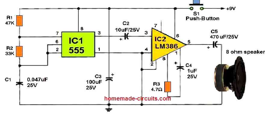
When S1 is temporarily pushed, C1 begins to charge via resistors R1 and R2. Pin 2 of the 555 oscillator/timer, IC1, is finally triggered. By driving pin#7 low, the IC begins to drain the capacitor via R2. This cycle will continue as long as S1 remains pushed.
The output of IC1 (pin 3) alternates in rhythm with the capacitor's charging and discharging, generating a sound frequency for IC2. IC2 is an LM386 low voltage audio power amplifier which amplifies the audio frequency's volume.
The speaker is employed to replicate IC1's tone frequency, that feels like a genuine buzzer sound. To get a low-frequency buzzing, you may want to increase the value of C1 to 0.1 uF.
For added stability, you can connect pin 7 of IC2 to ground through a 47 uF capacitor.
