IC 555 adjustable timer explained here can be adjusted from any time delay 1 second to 3 hours for operating any load through a relay control
The produced time delay is fully adjustable and the user has the freedom to set the time period as desired.
There are many ways of making simple timer circuits using different ICs and discrete components; here I have explained one such circuit using the ubiquitous IC 555.
The IC 555 is a pretty common electronic part among the electronic enthusiasts and is also very popular due to the involved simple configurations and low component count.
The two popular multivibrator modes of operation that’s associated with this IC are the astable mode, and the monostable mode. Both of these are useful configurations and have plenty of different applications.
Using the IC 555 in Monostable Mode
For the present adjustable IC 555 timer circuit design we incorporate the second mode of operation, which is the monostable mode.
In this mode of operation the IC is configured to receive a trigger externally, so that it’s output changes state, meaning if with reference to the ground if the output of the IC is zero, then it would become positive as soon as the trigger (momentary) is received at its input terminal.
This change in its output is sustained for a certain period if time, depending upon the external time determining components. Normally the time determining components are in the form of a resistor and a capacitor which together determine or fix the time period for which the IC output would hold its “high” position.
By changing either the value of the capacitor or the resistor, the timing can be altered as desired. The above time fixing components are termed as the RC component.

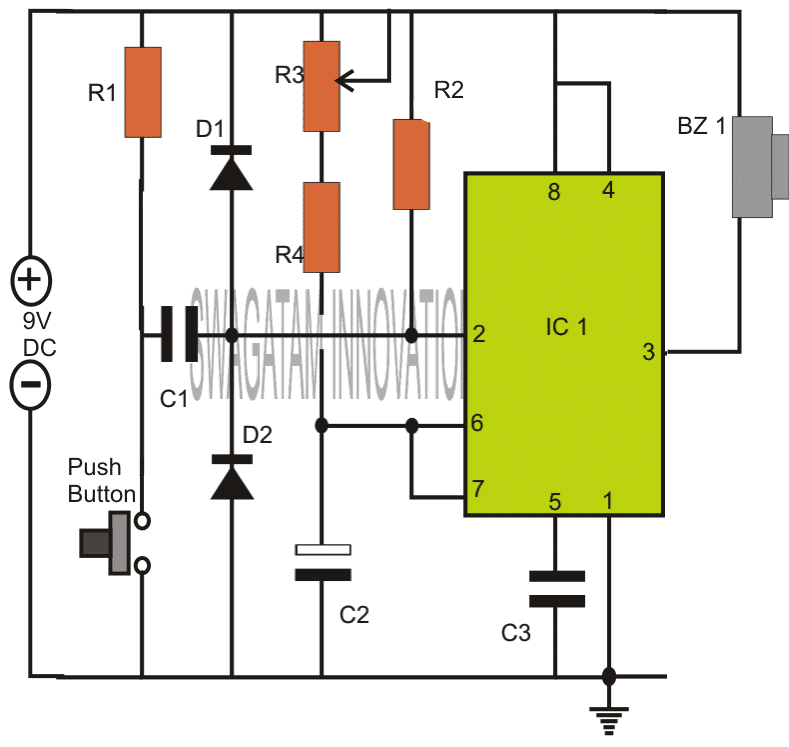
Note: Please connect the buzzer or the load between pin#3 and ground, and not between pin#3 and positive as incorrectly shown in the above diagram.
How the Circuit Functions
The 555 IC timer circuit above shows a very straightforward design where the IC 555 forms the central controlling part of the circuit. As discussed in the above section, the IC is in its standard monostable mode.
Pin #2 receives the external timing trigger from a push-to-ON switch. Once this switch is pushed, the circuit pulls its output to a positive potential and holds it until the predetermined time delay lapses.
The entire circuit can be built over a small piece of general PCB and housed inside a neat looking plastic enclosure along with the battery.
The output may be ideally connected to a buzzer for receiving the warning alarm after the set time lapses.


Parts List
- R1, R4 = 4K7,
- R2 = 10K,
- R3 = 1M pot,
- C1 = 0.47uF,
- C2 = 1000uF/25V,
- C3 = 0.01uF,
- IC1 = 555,
- Bz1 = Piezo Buzzer,
Push Button = push to ON switch circuit design requested by Mr.Bourgeoisie:

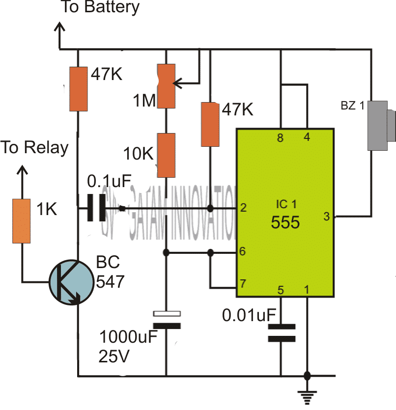
Please connect the buzzer or the load between pin#3 and ground, and not between pin#3 and positive as incorrectly shown in the above diagram.
Timer Circuit with Relay Switching
If you are wondering how the above simple timer circuits could be used for triggering a high power load through relay switching, then the following diagram will help you to implement the same by attaching a simple relay stage with the shown designs:

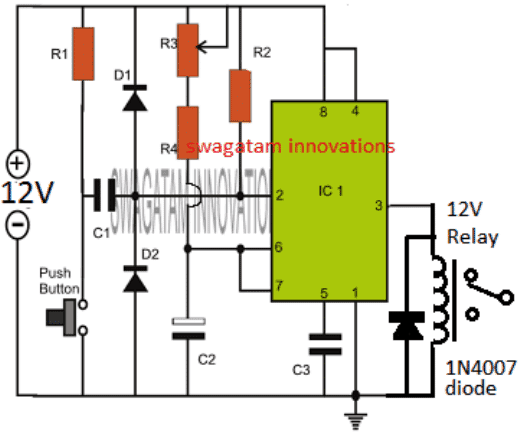
Parts List
All resistors are 1/4 watt 5%
- R1, R4 = 4K7,
- R2 = 10K,
- R3 = 1M pot, Linear
- C1 = 0.47uF Ceramic disc or PPC,
- C2 = 1000uF/25V, Electrolytic
- C3 = 0.01uF, Ceramic Disc
- IC1 = 555,
- Diode = 1N4007
- Relay = 12V/400 Ohm relay,
- Push-button = Any push-to-ON switch
Circuit Operation
In the shown diagram, when power is switched ON, the IC goes into a standby state, and no triggering action is initiated at this moment.
However as soon as the push button pressed, pin#2 is pulled down to ground which instantly triggers the IC in the monostable counting mode, and the relay is activated. The load connected with the relay is thus also activated.
The IC starts counting, and depending on the values of R3/R4, and C2, once the timing period gets elapsed, the IC resets to the previous standby mode deactivating the relay. The relay load also gets deactivated in this situation.
The cycle repeats each time the push button is pressed, enabling the user to achieve the relay triggered timing ON OFF feature in the circuit.
The timing interval can be increased or decreased to a given extent by suitably altering the pot R3 value and/or by modifying the value of C2.
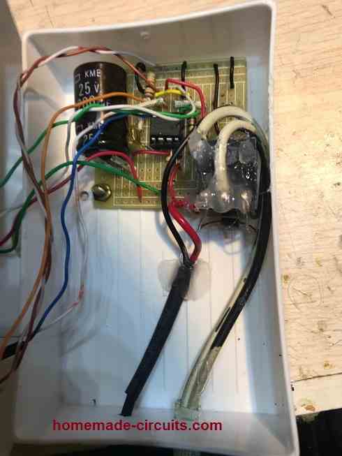
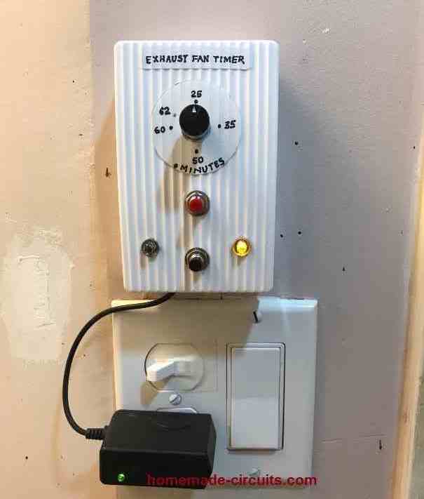
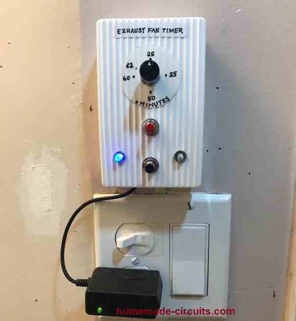
Prototype Images
The above explained 555 adjustable timer circuit was successfully built and tested by Mr. Vee, who is one of the dedicated readers of this blog, and a serious electronic hobbyist.
The circuit was appropriately modified to suit his personal timer application. The modified image can be viewed in the following diagram:

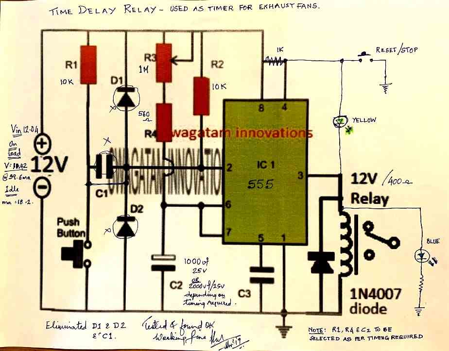
The prototype images of the above timer unit can be witnessed as shown below (built and tested by Mr. Vee):