In this post I have explained how to build a simple yet accurate timer circuit using the IC 4060 and some ordinary passive components.
Main Advantage of using IC 4060 as the Timer IC
I have already discussed this IC comprehensively in one of my previous articles, everything regarding its pin outs have been discussed there in detail. We studied that the IC 4060 is specifically suited for timer applications and also as an oscillator. In this article we’ll study how a simple versatile timer can be built using the IC 4060.
Other than the IC you would require just a couple of resistors, one pot and a capacitor for making this timer.
Referring the figure, the simplicity of the design becomes evident and therefore this circuit is perfectly suited for all electronic newcomers, who can easily build this project and enjoy its useful service.
As explained earlier in one my articles, the IC has an in built oscillator that needs just a few passive external components for making it tick.
Depending upon the values of the external RC components, the oscillation periods can be varied right from a few fractions of a second to many hours.
RC components refer to the values of the external time determining components consisting of a resistor or a pot and a capacitor.
The outputs produce a varied rate of time periods; each output generates time periods that’s exactly double to that of the previous output in a certain order of the IC pin outs.
Since here we want to use this unit as a timer we have selected the pinout which is last in the order as far the length of the time period is concerned, meaning we have selected pin #3 which generates the highest delay period.
The biggest advantage of making a timer using IC 4060 is that the involved timing capacitor can be kept as small as possible by increasing the complementary timing component value, which is the resistor.
This helps to keep the circuit simple, smaller and very sleek, unlike other timer IC like 555 which require high value electrolytic capacitors for generating even ordinary time delays.
How the Circuit is Latched when Time is Elapsed
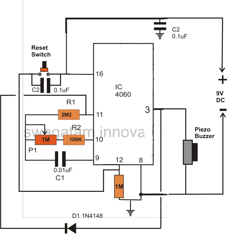
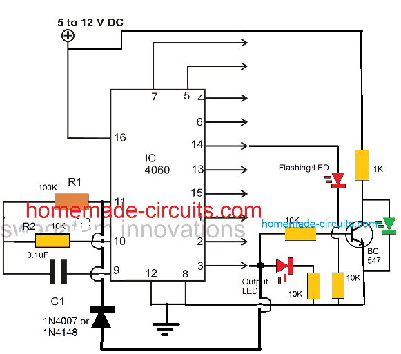
In the figure you can see a diode being introduced from the output pin #3 to one of the oscillator pin #11. This diode acts as a latching component, which latches the IC once the set time lapses and the output of the IC goes high.
If this diode is not inserted, the output would go freewheeling from logic high to logic low and keep repeating the time delays.
The circuit may be powered from a small 9 volt battery which will last almost for ever.
A buzzer is fitted at the output for the required indications of the timer output after the time delay has elapsed.
How to Reset the Timer
The IC may be reset simply by pressing the reset button or alternatively the circuit gets automatically reset when switched off and powered again.

How to Calculate Frequency or Time Delay of IC 4060 - The Formula

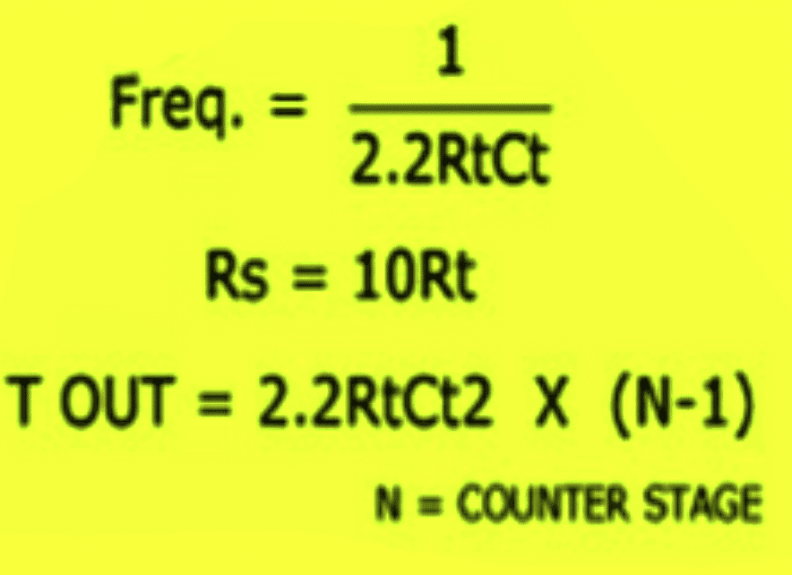
Or Alternatively the following standard formula for calculating the Rt and Ct values is:
f(osc) = 1 / 2.3 x Rt x Ct
2.3 is a constant as per the ICs internal configuration.
Rt will in Ohms and Rt in Farads
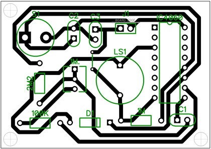
PCB Design

Adding a Relay
You can further upgrade the above design by adding a relay control to the output in order to facilitate an external mains AC load switching, as shown in the following image:

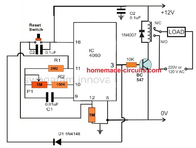
Remember the delay interval at pin3 can be increased by increasing the C1 value along with the P1 pot value. However, make sure that the C1 is always a non-polar, hence to increase its value you can connect many number non polar capacitors in parallel. For example you can connect non-polar 1uF capacitor as many numbers as you want for getting a desired long delay.
Delay OFF Timer (1 to 2 hours)
The IC 4060 can be also configured as a simple delay off timer with a delay of 1 to 2 hours or more.
A delay OFF timer basically switches ON the load initially, when the timer is switched ON, and then turns it off when the delay period lapses.

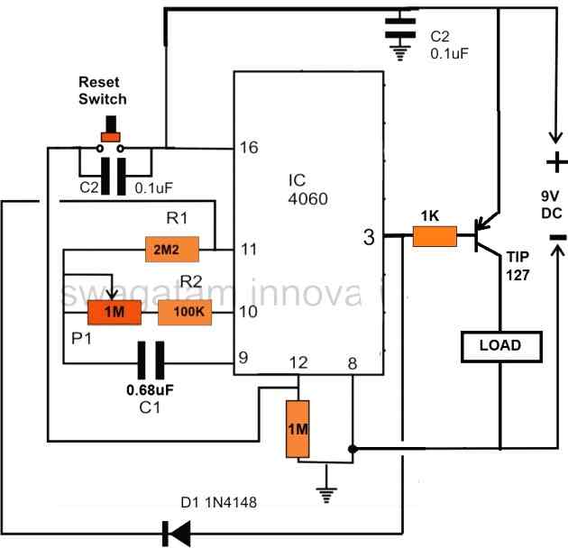
The circuit does not use a relay, instead powers the load directly through a PNP power transistor. However, if you want to include a relay, you can replace the TIP127 transistor with a BC557, and replace the "LOAD" with a relay. Don't forget to connect a freewheeling diode across the relay coil.
Note that here a PNP transistor is used for switching the load, this is done to implement the delay OFF function of the circuit. If a delay ON function is required, then the PNP transistor must be replaced with an NPN transistor.
Test Results for the above 4060 Relay based Timer Circuit
We would like to extend our deepest gratitude to Mr. Val for his exceptional expertise, unwavering dedication, and invaluable contributions to the development of our IC 4060 based timer circuit. Through his extensive knowledge and meticulous efforts, Mr. Val has not only modified and tested the circuit but also provided us with comprehensive documentation, including images and circuit diagrams, as given below.
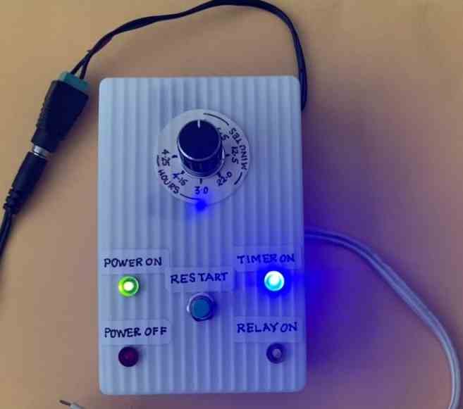
Specifications:
- RELAY ON WHEN SWITHCED ON
- DELAYED OFF TIME WITH POT SETTING

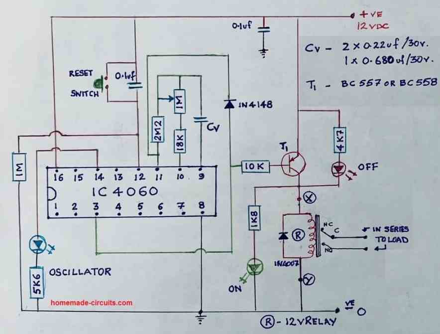

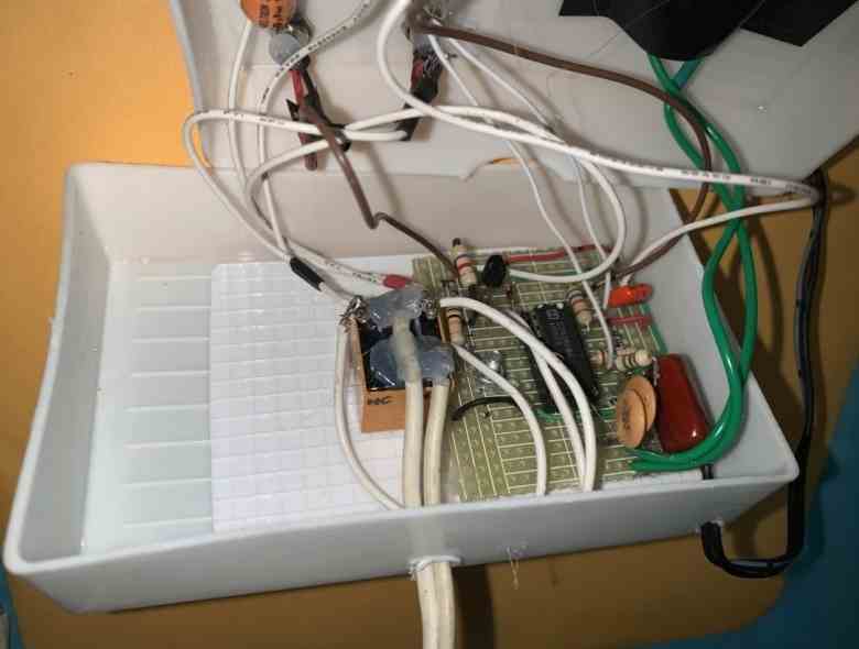

With great precision and attention to detail, Mr. Val meticulously tested the modified circuit, ensuring its flawless performance. His commitment to excellence and thoroughness in assessing every aspect of the design greatly impressed us. Through his unwavering efforts, we gained confidence in the reliability and efficiency of our timer circuit.
Understanding the Basic ON/OFF sequence of IC 4060 pinouts
The following video shows how a basic timer circuit may be configured using an IC 4060 and a few supporting passive components.

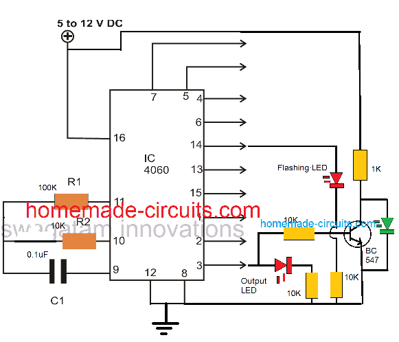
The schematic for the circuit discussed in the video can be visualized in the following diagrams:

The following image shows how to latch IC 4060 output by adding a diode across the selected output pin and pin#11

As we already know that the timing output or delay across all the shown output pins of the IC 4060 depends on the product of the values of R1 and C1, here pin#3 can be seen going after 32 logic pulses from pin#14 of the IC. Meaning when the LED at pin#14 completes 32 pulses, the LED at pin#3 switches ON, and switches OFF after another 32 pulses from pin#14. Identically you may find different equivalent rates at the other output pins of the IC.
This timing proportion is observed when R2 and C1 are selected to be 10K and 0.1uF respectively.
Simple Timer with Alarm
The next circuit is also designed using the CMOS IC CD4060, that includes a pulse generator and a counter. When power is switched on via S1, a reset voltage is given to the IC through C2. Simultaneously the IC built-in oscillator starts providing pulses to the counter.

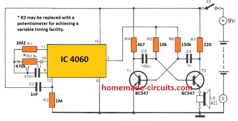
Following 213 clocks, the counter output (Q14) goes high, turning on the oscillator across T1 and T2. By doing this a sharp 3 kHz frequency that is emitted through an 8 ohm small loudspeaker. The circuit is powered down simply by turning off S1.
With the indicated R2 and C1, the buzzer will sound approximately An hour after the circuit has been started up. By upgrading R2 with a 1 M adjustable potentiometer, the buzzer time period could be varied from 5 minutes to 214 hours.
The potentiometer scale may be appropriately calibrated for quick setting up. The circuit utilizes hardly any current (0. 2 mA although the counter will be operating with 35 mA when the alarm signal is turned on) thus that a 9 V battery should promise quite an extended life.
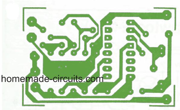
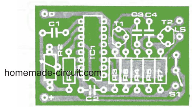
PCB Design and Component Layout for the above timer with alarm can be seen below: