
In this article I have explained many different methods of modifying voltage regulators ICs to improve their voltage and current handling characteristics. We learn how to externally modify these regulators using transistors and ICs for upgrading their current and power handling capacities.
We discuss how to modify 78XX ICs, LM317 ICs, LM350 ICs, and LM323 ICs.
Voltage regulators exist in two versions, in that their output voltage can be either positive (LM78XX series) or negative (LM79XX series) with respect to ground. They can be found in TO-220 or TO-3 packages. The pinout of an LM78XX is shown in figure 1.
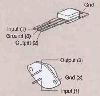
That of the LM79XX is different: the INPUT and GROUND pins are interchanged. Their main characteristics are as follows:
- Maximum input voltage of 35 V for regulators from 5 V to 18 V, and 40 V for regulators from 20 V to 24 V
- Maximum output current of 1 A to 1.5 A (internal limitation)
- Internal protection of the output transistor
- Thermal protection
- Protection against short circuits
- Available in output voltages of 5 V, 6 V, 8 V, 9 V, 12 V, 15 V, 18 V, 20 V, and 24 V
Modifying 78XX Voltage Regulators
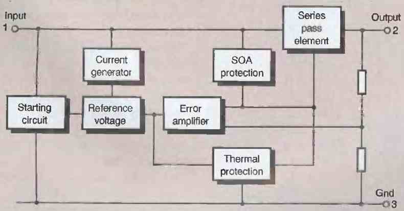
Their internal circuit diagram is shown in figure 2. The reference voltage, current generator, various protections, and output power stage can be distinguished.
In some cases, using only a voltage regulator is not sufficient, and additional components are necessary.
We propose four examples of the most common:
Insufficient regulator output current
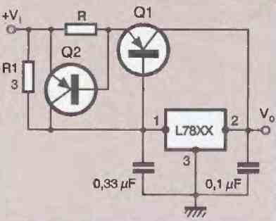
The circuit shown in figure 3 provides a solution to this problem. It allows for a significant output current while retaining protection against short circuits. Two transistors and two resistors are required. The resistance R is calculated as follows:
R = VbeQ2 / I
R = 0.7 / I
Need for a symmetrical power supply using a single positive voltage regulator:
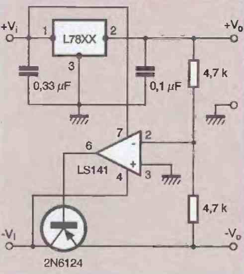
The circuit used is shown in figure 4. It requires a power transistor, an operational amplifier, and two additional resistors. The operation is very simple.
Two primary voltages, one positive and the other negative, power the circuit.
The voltage from a voltage divider divided by two and connected between the voltage regulator output and negative voltage is applied to the inverting input of an operational amplifier whose output controls the base of a power transistor. If the +Vo voltage changes, the -Vo voltage changes by the same proportion.
Need for a variable power supply using a fixed regulator
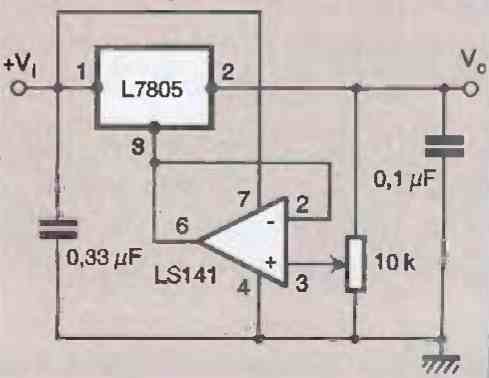
The circuit is shown in figure 5. An adjustable resistor and an operational amplifier are sufficient to adjust the output voltage. The operational amplifier is configured as a follower.
Its non-inverting input is connected to the potentiometer wiper which allows a variable voltage to be applied to it.
The GND pin of the regulator is not connected to ground but to the output of the amplifier whose voltage allows the voltage Vo to be decreased or increased.
Powering a voltage regulator from a voltage higher than the permissible one
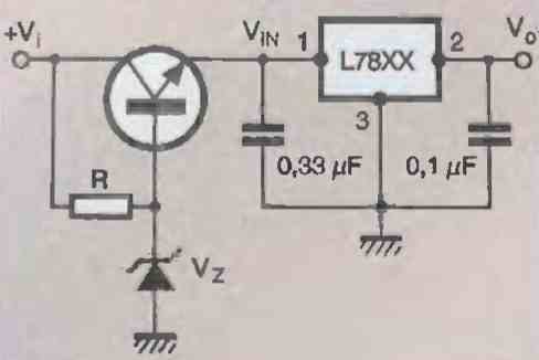
The circuit shown in figure 6 is then used. A transistor, a zener diode, and a resistor are sufficient to reduce the Vin voltage to an acceptable value for the regulator.
The output voltage of the transistor is equal to the zener voltage reduced by the Vbe voltage.
Modifying LM323 Regulator
The LM323 is a fixed voltage regulator presented in a TO-3 package that provides a positive output voltage of 5V and can deliver a current of 3A. Its main characteristics are as follows:
- Initial precision of 1%
- Maximum output current of 3A
- Internal current and temperature limitation
- Output impedance of 0.01 ohms
- Minimum input voltage of 7.5V
- Power dissipation of 30W If a current of 3A is insufficient, the circuit shown in Figure 7 can be used.
The modified circuit represented here allows, by means of three LM323s and two operational amplifiers, to increase the output current to 10 A.
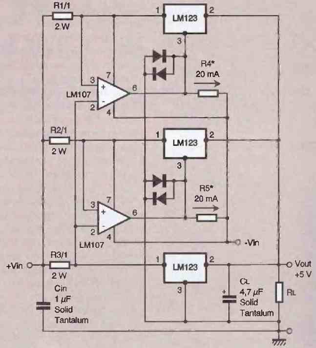
An unregulated negative voltage is required for the operation of the operational amplifiers. The regulators retain their overload protection.
Another practical application of the LM323 is the design of an adjustable power supply from 0V to 10V and delivering a current of 3A, the circuit of which is shown in Figure 8.
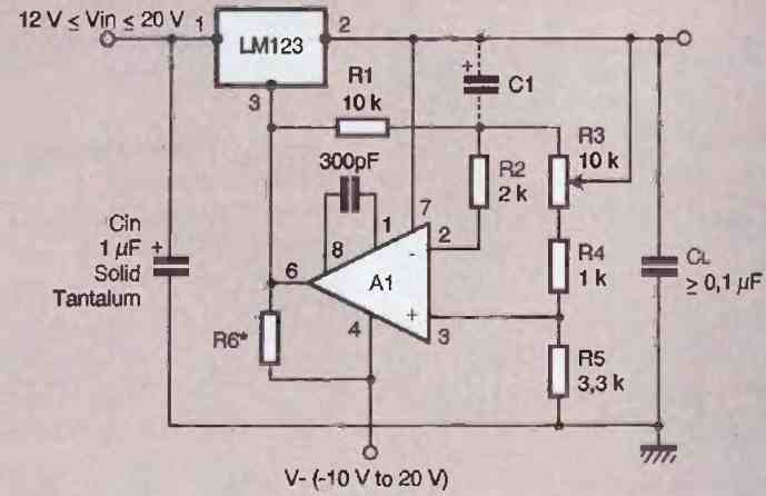
An LM101A type operational amplifier is required. It is connected to the LM323's ground pin, allowing the regulator's output voltage to be adjusted.
An additional negative power supply, which does not necessarily have to be regulated (between -10 and -20V), powers the operational amplifier.
Modifying LM317 Voltage Regulator
The LM317 is an adjustable voltage regulator most commonly available in a TO-220 3-pin package.
It is capable of supplying a current of 1.5 A and allows for a variable output voltage between 1.2 V and 37 V.
It is remarkably easy to use as it only requires two external resistors to set its output voltage.
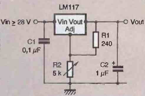
Note that its regulation is better than that of fixed voltage regulators. The circuit shown in figure 10 above gives the classic configuration of an LM317.
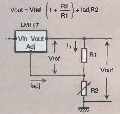
The next figure above allows for the calculation of resistor R2 according to the desired output voltage, knowing that the voltage Vref is equal to 1.25 V and that the value of resistor R1 is 240 Ω.
Internal Circuitry and Characteristics of LM317
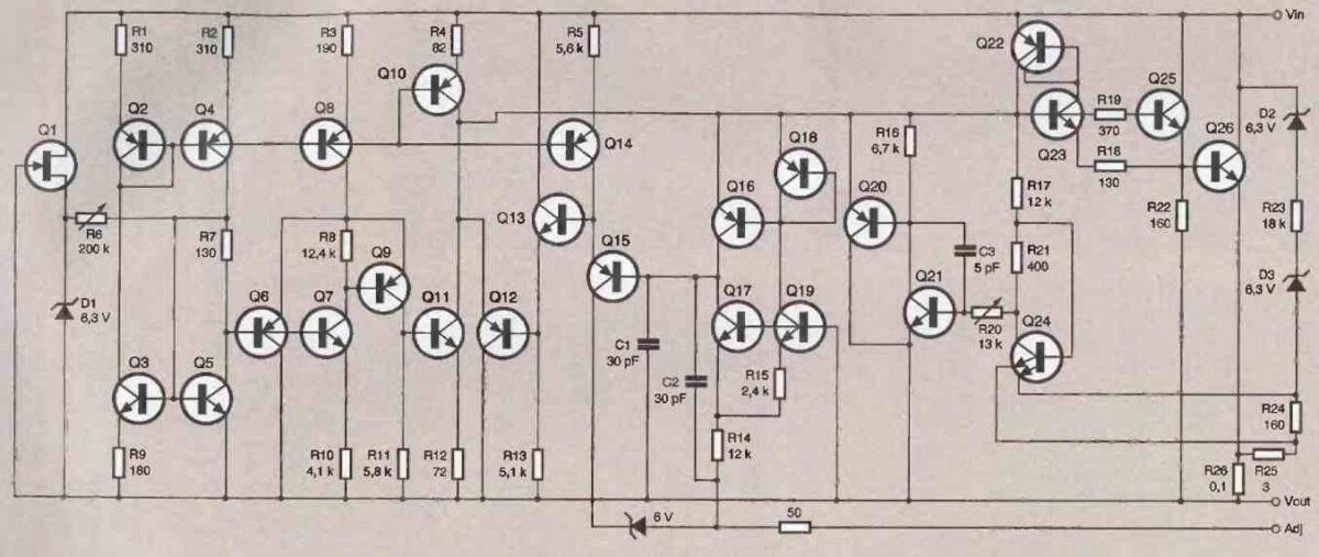
For information, we provide in figure 12 the internal circuitry of the LM317. Its main characteristics are as follows:
- Maximum output voltage tolerance of 1%
- Maximum line regulation of 0.01%
- Maximum load regulation of 0.3% (1.5 A)
- Minimum output voltage of 1.2 V
- Output current of 1.5 A
- Constant current limitation according to temperature
- Output protected against short circuits The LM317 circuit allows for the design, using external components, of voltage-regulated power supplies capable of delivering a very high current.
We propose three proven schemes that are fully usable:
8 Amps from LM317
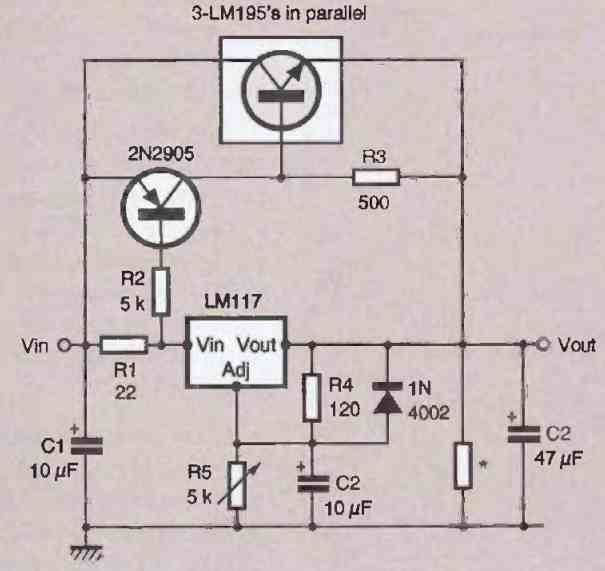
Figure 13 above shows a modified circuit using three LM195s placed in parallel and capable of delivering a current greater than 8 A.
The capacitor C1 must be a tantalum model. The resistor placed between the output pins of the power supply and marked with an asterisk must provide a minimum load of 30 mA when the circuit is not delivering any current.
LM317 Laboratory Power Supply
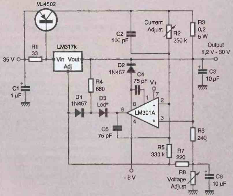
The modified circuit shown in Figure 14 above is very interesting because it allows for the inexpensive construction of a true laboratory power supply (constant voltage and constant current). It can deliver an output voltage between 1.2 V and 30 V and can deliver 5 A.
Potentiometer R2 adjusts the output current while R8 adjusts the voltage to the desired value. A LED diode placed at the output of the operational amplifier control stage indicates when the circuit is in constant current mode.
Using Parallel LM317 for Current Boost
The circuit shown in Figure 15 below is remarkable for the very high current it can deliver. It can deliver 4 A, or about 1.3 A per regulator, as three LM317s have been placed in parallel.
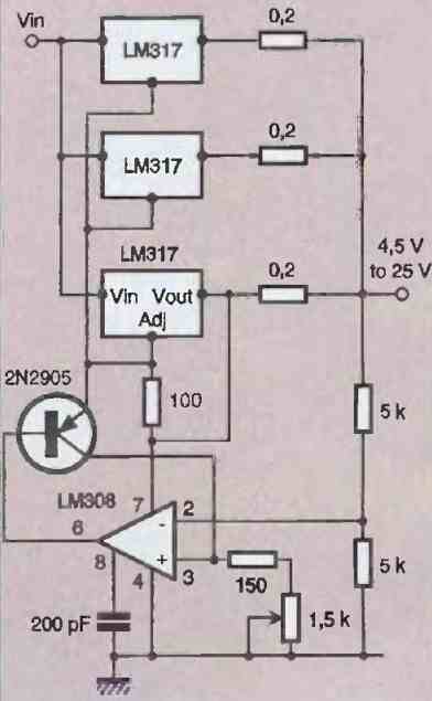
For our own circuit, we have even tried 12 regulators in parallel, giving us a current greater than 15 A. The resistors placed at the output of each LM317 allow the current delivered by each of them to be balanced.
The voltage regulation system uses an operational amplifier whose inverting input is connected to the midpoint of a voltage divider that measures the output voltage. Its output controls a transistor whose emitter is connected to the voltage adjustment pins of each LM317.
Modifying LM350 Voltage Regulators
The LM350 integrated circuit is an improved version of the LM317 as it allows for a maximum output current of 3A. Its pinout is the same as LM317, and its implementation only requires two resistors (see Figures 8).
It offers the same current limiting and temperature protection features. Its main characteristics are as follows:
- Minimum output voltage of 1.2V
- Guaranteed output current of 3A
- Thermal regulation
- Output protected against short circuits
- Constant current limitation as a function of temperature
- Maximum line regulation of 0.01%
- Maximum load regulation of 0.3.
As with other regulators, multiple LM350s can be coupled together and external components can be added to increase the output current significantly.
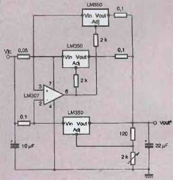
The circuit diagram in Figure 16 provides an example that allows for an output current of 10A using three LM350s and a control operational amplifier. Note the 0.1 ohm balancing resistors.
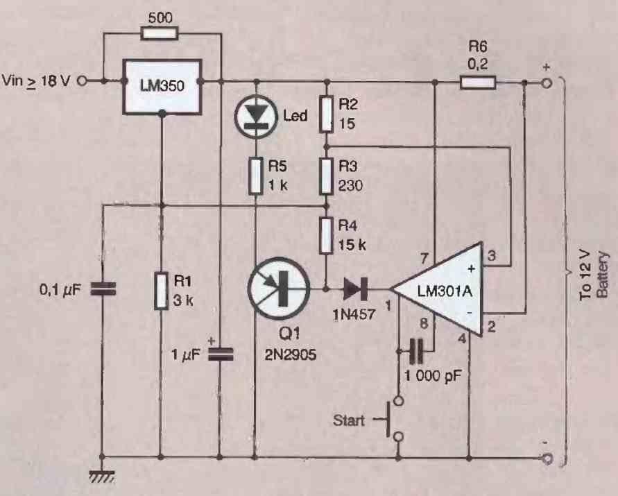
Automatic Battery Charger using LM350
Another interesting modified application is shown in Figure 17 below. It is a 12 V battery charger. Pressing the "START" pushbutton initiates the charging process, which ends when the battery has reached its nominal charging voltage of approximately 13.8V. Resistance R6 is responsible for this measurement.
We have now reached the end of the description of the most common regulators and some very useful applications. We have selected the most relevant ones to interest our readers among the many existing applications.