In this post I have explained a few circuit concepts which can be employed for converting or modifying any ordinary square wave inverter to a sophisticated sine wave inverter design.
Before studying the various designs I have explained in this article, it would be interesting to know the factors which typically makes a sine wave inverter more desirable than a square wave design.
How Frequency Works in Inverters
Inverters basically involve frequency or oscillations for implementing the boost and inversion actions. The frequency as we know is generation of pulses at some uniform and calculated pattern, for example a typical inverter frequency may be rated at 50Hz or 50 positive pulses per second.
The fundamental frequency waveform of an inverter is in the form of square wave pulses.
As we all know a square wave is never suitable for operating sophisticated electronic equipment such as TV, music players, computers etc.
The AC (alternating current) mains that we acquire at our domestic mains outlet also consists of pulsating current frequency, but these are in the form of sinusoidal waves or sine waves.
It's normally at 50Hz or 60Hz depending upon the particular country utility specs.
The above mentioned sine curve of our home AC waveform refers to the exponentially rising voltage peaks which constitute the 50 cycles of the frequency.
Since our domestic AC is generated through magnetic turbines, the wave form is inherently a sine wave, so doesn't require any processing further and becomes directly usable in homes for all types of appliances.
Conversely in inverters, the fundamental waveform are in the shape of square waves which needs thorough processing in order to make the unit compatible with all types of equipment.
Difference between Square Wave and Sine Wave
As shown in the figure, a square wave and sine wave may have identical peak voltage levels but the RMS value or the root mean square value may not be identical. This aspect is what that makes a square wave particularly different from a sine wave even though the peak value may be the same.
Therefore a square wave inverter working with 12V DC would generate an output equivalent to say 330V just like a sine wave inverter operating with the same battery but if you measure the output RMS of both the inverters, it would differ significantly (330V and 220V).

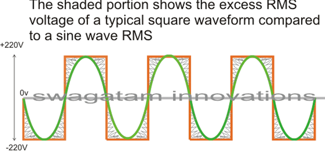
The image incorrectly shows 220V as the peak, actually it should be 330V
In the above diagram, the green colored waveform is the sine waveform, while the orange depicts the square waveform. The shaded portion is the excess RMS which needs to be leveled of in order to make both the RMS values as close as possible.
Converting a square wave inverter into a sine wave equivalent thus basically means allowing the square wave inverer to produce the required peak value of say 330V yet having an RMS just about equal to its sine wave counterpart.
How to Convert/Modify a Square Waveform to Sine Waveform Equivalent
This can be done either by carving a square wave sample into a sine wave form, or simply by chopping a sample square waveform into well calculated smaller pieces such that its RMS becomes very close to a standard mains AC RMS value.
For carving a square wave to a perfect sine wave, we can employ a wien bridge oscillator or more precisely a "bubba oscillator" and feed it to a sine wave processor stage. This method would be too complex and is therefore not a recommended idea for implementing an existing square wave inverter to a sine wave inverter.
The more feasible idea would be to chop the associated square wave at the base of the output devices to the required RMS degree.
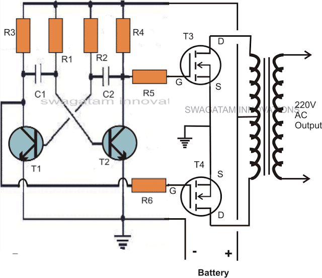
One classic example is shown below:
The first diagram shows an square wave inverter circuit. By adding a simple AMV chopper we can break down the pulses at the base of the relevant mosfets to the required degree.
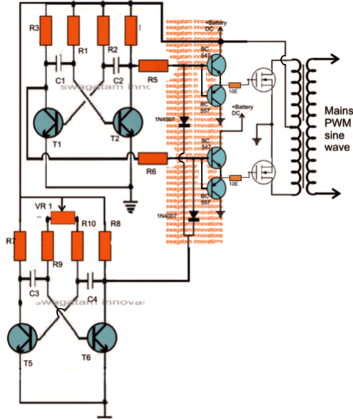
Modified square wave to sine wave equivalent inverter version of the above circuit.
Here the lower AMV generate pulses at high frequency whose mark/space ratio can be suitably altered with the help of preset VR1. This PWM controlled output is applied to the gates of the mosfets in order to tailor their conduction into the stipulated RMS value.
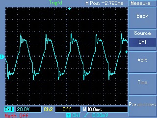
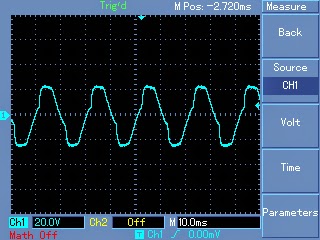
Expected typical waveform pattern from the above modification:
Waveform at the mosfet gates:
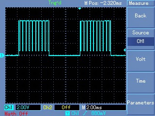
Waveform at the output of transformer:
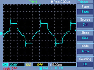
Waveform after proper filtration using inductors and capacitors at the output of the transformer:
Parts List
R1, R2, = 27K,
R3, R4, R5, R6, R7,R8, R9, R10 = 1K Ohms,
C1,C2 = 0.47uF/100V metallized
C3, C4 = 0.1uF
T1, T2, T5, T6 = BC547,
T3, T4 = any 30V, 10amp mosfet, N-channel.
D1, D2 = 1N4148
VR1 = 47K preset
Transformer = 9-0-9V, 8 amp (specifications must be selected as per the output load for correct powre optimization)
Battery = 12V,10AH
Getting Better Efficiency Rate
The above explained conversion or modification will provide around 70% of efficiency with the achieved RMS matching. If you are interested in getting better and precise matching then probably a an IC 556 PWM waveform processor would be required.
You would want to refer to this article which shows the principle behind modifying a square waveform into a sine waveform using a couple of IC555.
The output from the above mentioned circuit can be similarly fed to the gate or the base of the relevant power devices which are present in the existing square inverter unit.
A more comprehensive approach may be witnessed in the this article where an IC 556 is used for extracting precise PWM based modified sine wave equivalents from a square wave sample source.
This waveform is integrated with the existing output devices for implementing the intended modifications.
The above examples teach us the simpler methods through which any existing ordinary square wave inverter may be modified into a sine wave inverter designs.
Converting into an SPWM
In the above article I have explained how the waveform of a square wave inverter could be optimized for getting a sine wave kind of waveform by chopping the square wave into smaller sections.
However a deeper analysis shows that unless the chopped waveform is not dimensioned in the form of SPWMs, achieving a proper sinewave equivalent may not be possible.
To satisfy this condition an SPWM converter circuit becomes essential for carving out the most ideal sinewaveform from the inverter.
The basic idea is to chop the output power devices with sine wave pulse width modulation, so that the power devices force the transformer winding to also oscillate in the SPWM mode and ultimately generate an optimized pure sine wave at the secondary side. The magnetic induction of the pulsed SPWM across the transformer winding finally gets the shape of a pure sine wave due to the inductive filtration of the transformer winding.
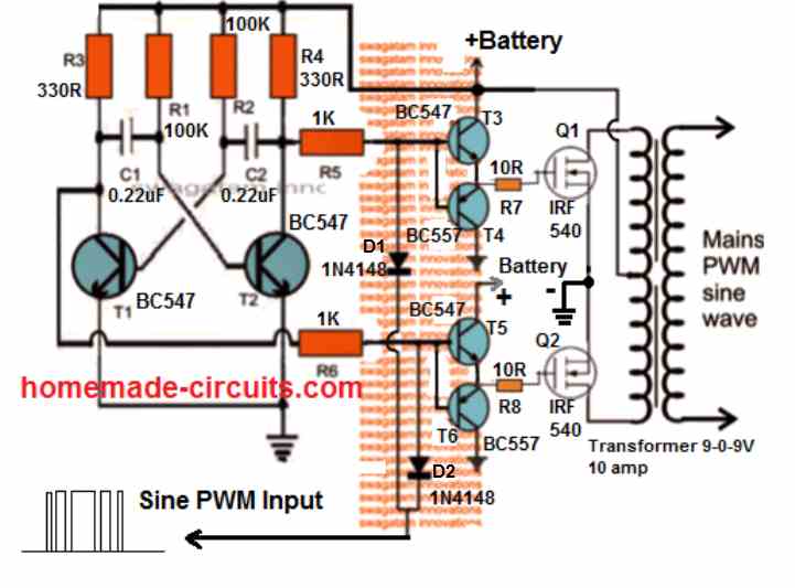
The following diagram shows how this could be effectively implemented with the concept discussed above.
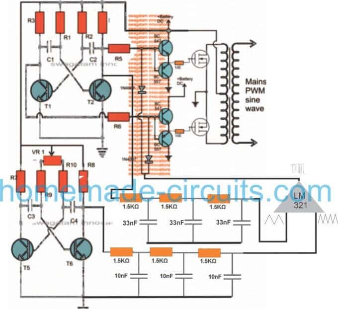
Through one of my earlier articles we understood how an opamp could be used for creating SPWMs, the same theory could be seen applied in the above concept. Two triangle wave generators are used here, one accepting the fast square wave from the lower astable, while the other accepting slow square waves from the upper astable and processing them into corresponding fast and slow triangle wave outputs, respectively.
These processed triangle wave are fed across the two inputs of an opamp, which finally converts them into SPWMs or sine wave pulse widths.
These SPWMs are used for chopping the signals at the gate of the mosfets which ultimately switch the waveform over the connected transformer winding for creating an exact replica of a pure sine waveform at the secondary side of the transformer through magnetic induction.

so if the LC filter is added to the circut will i be able to run a 20 watt ac motor load without having the adverse effects on the pump ????
LC will reduce harmonics and will help the motor to run with less noise, less heat and more efficiently
Salut Swagatam..
J'aimerais bien avoir a la sortie de l'onduleur 120 volts.pouvez vous me donner le shema?
Merci.
Salut Wileps,
you simply have to use a transformer having an 120V rated secondary winding, rest everything can be as is
il suffit d'utiliser un transformateur ayant une 120V évalué enroulement secondaire, du repos tout peut être aussi est
Sir can you please suggest me what is wrong?
1) If I connect a load with morethan 100watt the Mosfet are getting hot and even some of the component in the circuit are damaging, like the ware i used for making jumpers and some line in the viroboard.
2) This new Inverter that I build (sinewave) cannot operate fan. I tried it with a table fan, and the fan is only emitting louder sound as if it is going to bust.
In testing this sinewave circuit, I used:
*12v 20A battery.
*Transfomer removed from 500va UPS and,
*IRF3205 mosfet.
Thank you sir.
Aminu,
The PCB is getting hot because the tracks or the jumpers are not able to bear the higher current level, you should use thicker wires and tracks for the PCB, and use a big heatsink for the mosfets.
Adjust the PWM and see which PwM setting produces the most suitable results for the fan.
actually the pot should be adjusted first for setting the output voltage of the trafo at the correct level, only after this it's recommended to connect the load
Good Morning Sir,
Am back with the result.
As you asked me to do, so I did it.
All the pots are working, because the LED's light is varying.
Now, I changed the pot to 473. May be my moltimetre has fault that is why I cant see the changes in the AC volatge. But, even the bulbs I conneced did not show any change.
Ok, Thank you Sir,
I will give it try and update you with the result soon.
Again Sir,
With last and recent inverter I builded, I understand that, both cannot work well with transformer removed from old UPS.
I tested with two transfo, one is 7.1-0-7.1 removed from 500va UPS and other has no detail but it was removed from 750va UPS non of them is able to operate PC, the transistor become hot instantly but they work on TV and bulbs.
Finaly, I tried the other tranfo that I'am using which is rated 12-0-12 5A it operate PC normaly and light 26watt bulb at same time, so due to its low current (5A) it cannot operate the TV.
Sir, I need your help on what best transfo should I use, that can operat many electronic apliencies. Because, Buying or winding new transfo may cost too much.
Iam very grateful Sir,
Thank for the helps.
Aminu, use 33uF, or 47uF, or any such high value capacitor in place of the 102 capacitors and connect lED in series with R7, R8…now check the LED illumination, it should flash alternately and the flashing should change on both the LEDs oppositely as the pot is moved….this will confirm your PWM section transistors are working or not.
once this is confirmed positively you can again replace the capacitors with the 102, and if this time it doesn't work then it could be the 102 caps which can be deemed faulty.
7V trafo is the correct one and will work optimally when the PWM is attached and adjusted correctly.
Sir, You are great!!!
Iam happy to informe you that, I have builded this Simple SineWave Inverter. Now, Its working normal and it provided me with full current.
But, I did not used IC555 stage, I used the complete circuit above since it seems more familier to me.
The only problem i got was in BC557/BC547 stage where one of the BC547 used is damaged and it allows the high volt to pass through it, Though based on your resent reply I have identified and solved problem.
Now, Another Issue is on POT and some other component I used as result of their scarcity.
1) I used 473 pot, then another new 473 and finaly I change to 503 pot still I cant see any difference in AC outpot when varying both the pots that i used.
Anything wrong?
2. I used 2A102j instead of 680pf.
Can this affect the working of the pot or can it damage the applience operate with this inverter?
Thank you very much Sir.
Good Morning Sir,
I have build this new circuit, all 3 parts are made seperataly in one board, but I did not test any.
I want you to help me as usual with a trick on how to test the following stage.
1. the IC555 stage without oscilloscop.
2. BC557/BC547 stage.
Thank you very much Sir, Iam very proud of you.
Hi Aminu,
first check the circuit without the lower PWM stage
assuming your 50Hz upper inverter works normally, and it should. initially keep the PWM link from the lower circuit T6 disconnected and check the voltage at the collector of T6 which should vary as the pot is varied, next confirm the frequency at this point and make sure it's 2 to 10 times higher than the frequency of the upper stage (50Hz), depending on the value of the capacitors C3/C4
once these are confirmed you ca integrate the PWM feed as indicated in the diagram for the final analysis.
hi bro
how are you ?
can you please show a simple lc filter for the 220v side,i have 2.5uf ac cap
how much is the l=?
sorry bro, I have not investigated the concept yet so I won't be able to suggest much, however here's one link which you can refer to, it has an output filter example stage clearly explained, i hope it helps:
https://www.wpi.edu/Pubs/E-project/Available/E-project-042507-092653/unrestricted/MQP_D_1_2.pdf
hello Mr. swagatam
i have some doubts regarding this project.
1)is this a square wave or a pure sine wave inverter.
2)in the modified circuit there are 2(+ve) terminals but i cant see a -ve terminal,is there some thing wrong with the diagram or am i missing something which is obvious in epic proportions ??
pls help.
Hello Akshay, The second variant is as good as a pure sine inverter, you might possibly need to put an LC filter at the output for enhancing the results, which could help make the output much like a pure sine wave.
All the earth symbols in the diagram refer to the negative line and will need to be connected with the battery negative
Hello Mr. Swagatam.
I have couple of small questions regarding this project which might seem trivial,but i would be be grateful if u did .
1)is this a sine wave or a square wave inverter ?
2)In the modified circuit there are 2 (+ve)positive terminals and i dont see any negative terminal.is the diagram correct or m i missing something?
much appreciated.
Thank you very much Sir.
I will try this updated version too.
1. Sir, If I use IC555, is it necessary to do BC557/547 stage?
2. In my old inverter builed from first circuit (SquareWave) I used 2A473j cap instead of 474j and the inverter is still working. Can this change course problem to the appliances Iam operating with it, Sir?
Thank very much Sir.
I will contact you very soon if am through with this version and the other one that convene ic555 pmw and transistive AMV.
Hi Aminu,
If you are using PWM then the BJT will become necessary, to enable a better working of the mosfets.
473 will give 10 times higher frequency than 474, that means your inverter would be running at 500 Hz which can be bad for the connected appliances which are specified to run at 50Hz or 60Hz.
so make sure the frequency of the inverter is 50 Hz at 220V or 60Hz at 120V
When I built this circuit in the past and I normally get the correct voltage but wrong frequency I realized you modified it, I'll try this updated version…. Could I use an arduino to generate pwm and send it to the diodes I'm wondering if the voltage would be too low because the arduino would be sending a 5v or less pwm Signal
the frequency has nothing to do with the configuration, it's simply due to the PWM freq interfering with the base 50 Hz frequency….if you analyze with a scope you would be able to get the correct figures.
As for the modification a reassessment made me realize that actually the previous design too was safe and had no problems, earlier I thought may be the PWM would damage the BC557, then I realized that with no emitter current that would be impossible….so the new diagram is as good as the previous one….technical both are safe.
5V would be fine as PWMs, no issues.
Again Sir,
1) This 680pf caps is not availabe in my area. Is there any changes in Caps and resistors of PMW?
2) If I want use IC555 as PMW what is the value of following components?
A) Resistors,
B) Trimpot and
C) Caps.
Thank you Sir for your time and help.
680pf is not critical, you can use any cap below 0.1uF
you can try the following 555 circuit, just remove the transistor stage and connect pin3 directly with the diodes:
https://www.homemade-circuits.com/2012/05/making-adjustable-electromagnet-circuit.html
you can use 12V with the design
Hi Sir , good work u are doing for everyone pls I need the connection of the LM321 that connect the bc556 and BC 547
Olufade, Please find the pinouts of the IC here:
https://www.homemade-circuits.com/single-opamp-ic-lm321-datasheet-ic-741/
You are great Sir,
Thank you very much… And I will do as you mentioned.
But, Sir
1) This 10E resistors seem to be identical with the 10R resistors used in the old circuit.
Their colour are: Brown:Black:black:gold. Right?
2) If I used 1.5watt for all resistors in the circuit what will happen?
Thank you once again Sir. May God help you, protect you and reward you.
thank you Aminu, I have not removed the BC557 actually, just added a resistor at its base for preventive the damage.
yes that's right, but the 10 ohm is not critical, it can be any resistor below 50 ohms.
higher wattage resistors will not do any harm to the circuit just consume unnecessary space on the board.
Sir, I think my problem is not in the building the above two AMV, but rather in the BC557/BC547.
How can I check, If they are correctly configured?
I cross checked the two circuit I made with two AMV and I learnt that, now only mosfet is instantely becoming hot. And while connecting the battery to the circuit there is little spark and the battery wire becoming hot too.
Thank you Sir for all your help.
Aminu, You will have to configure them as shown in the diagram with correct lead connections, I also told you to measure the frequency, until you confirm the frequency at the various nodes, you cannot be sure about the results.
Thank you Sir, I will try this Lamp.
Again, on the issue of venturing…
I mean I want to build a very cheap, simple and brighter lamp that has less battery power consumption.
For Example;
A lamp with 3 to 6 bright LED type opperated with only two AA batteries.
Because, here in the market, there are many kind of this lamp, but people complaining about the quality, the battery power consumption and it's ability to opperate only on 3 AA Batteries.
So, I want, if available, any component to make changes.
Aminu, you can try the following design initially:
https://www.homemade-circuits.com/2012/10/1-watt-led-driver-using-joule-thief.html
Ok Sir.
I anticipated those bc557/bc547 to damage because they got smoke when the first problem happen.
Now, I decided to give up this circuit and build new one.
While, building new one, Sir can you please guide me on how to test any part I buid before proceding to the next stage. Thought, I mastered the first circuit but still I need some help.
I also have multimeter but, I think I lack knowledge on how to use it properly.
Aminu, the BC/547/BC557 cannot go in smokes unless something's wrongly configured.
anyway, in the new circuit first make sure the two AMV circuits upper and lower are oscillating correctly at the specified rates.
you might be having a frequency range in your meter, use it to measure the frequency across the collector and ground of the transistors.
the upper circuit must show around 50Hz…while the lower circuit should indicate some higher value depending on the pot adjustment.
Yes Sir, I have rectified it. But, another problem, one bc557+bc547 part is damage. I discovered this after I removed the transfo and I left only a board with two mosfet, then I used LED across the two 10R resistors but, the LED did not light up. While if I connect the normal one with Positive battery power it light up, and if i repeat the procedure on other side with Nagative battery power, the LED will not ON.
1. Sir, can this procedure work?
2. And is it true that if the circuit is working the LED will light up? Because, I dont have another working circuit to confirm it, other than the above Square wave I made.
Again, Sir do you have an idea on how to make a simlpe, cheap and few components brighter touch light operated on 2*AA batteries that last longer than usual?
I'am asking you this because, I have recenty graduated and I don't what to stay for Government to give me job, that is why Iam blindly searching for an opportunity.
I learnt that, our main problem in area I'm leaving is Light, that was what brought an Idea of inverter to my mind, even though there are many inverters in market that are very cost. And I have a little knowledge on electronics and I can devote my time on it freely and tirelessly.
I have no words to express a gratitude.
Am proud of you sir.
Thank you very much for your time, help and king responses.
I discovered again, I included two 27k instead of for 1k at PWM.
Thanks, for the help Sir.
yes that's a mistake, I hope you'll correct it soon…
Sir, I have discovered the problem.
I learnt that, I placed the VR wrongly that is why Iam facing the problem.
Now I changed new mosfets, and I disconnected the PWM section but the output AC voltage is very low.
I can see VR has 3 leg, one in isolation part and other 2 in the same part. And I have four resistor's leg to connet them with it.
So, Which VR leg should I connet to 1k and 27k resistors.
Sir please help me as usual How to place this pot, because I tried it in any direction but it did not work.
Thank you Sir!
Aminu, as i indicated before the trafo voltage rating should be lower than the battery voltage for enabling a correct voltage at the output, so make sure this rule is followed.
the pot two end leads should be connected with R9/R10 while the center lead connects with the positive rail.
Sir, as soon as I connected it to the battery, the mosfet is instantly become too much hot and some other component will start smoking. And I tried it without load as you suggested but the problem is remained unchange
But, it worked by the time i build the circuit. This problem was started when I loaded a laptop.
And, Sir is there any way to check the whether the circuit is fine or not before connecting it to the transformer.
Thank you Sir.
Aminu, that will never happen if your circuit is oscillating correctly, or if the mosfets are correctly connected or are not faulty.
disconnect the gates of the mosfets, and check the frequency at the collectors of the T1/T2, then at the base of the BC547/BC557, and finally at their emitter junctions….all should show an approximately 50Hz without the PWM connected.
after connecting the pWM this must increase as per the PWM frequency.
Probably Sir!!
Sir, I dont know what is wrong with my inverter that i build with the 2nd circuit, its now damage 3 mosfet and sometimes its connection is burning untill i make jumper with copper.
Pls, help me sir.
And can I use the inverter I made from 1st circuit to on tv? Because, I try it now but the tv is ON and after some mints it OFF and instantly ON again.
Thank you very much sir.
Aminu, that will be difficult to troubleshoot, you will have to find it yourself what might have gone wrong in your circuit. As you can see the concept is explained comprehensively in the above article, you will have to thoroughly understand how the two circuits are related and how these are supposed to interact, and how the pot needs to be set for an optimal response.
you can check the output voltage without any load, and check whether the pot adjustment varies it or not…it should vary
Great work sir,
This circuit is very interesting, I used the first circut to charge and on a laptop and a bulb. this is amazing.
The partlist i used are;
1. 12-0-12v 5A transfo.
2. Two FP50N06 mosfet
3. The fist circuit orsillator and,
4. 12v 20ah battey.
With this, I on a laptop and a 10 watt bulb for 30 mint and the battey never empty.
But, the transfo generate some sound and little heat and the two mosfet take less heat than transfo, So I dont know whats wrong.
Am sure my Teacher Sir Swagatam will help me if there is problem.
Thank you for all your help to us, and may god bless you and protect you.
thanks Aminu, such problems are difficult to judge….most possibly it could be due to a low quality transformer, because most companies try to save money on copper and iron and end up creating non-standard designs, and compromising on the quality of the trafos….it is difficult to get a really professionally designed trafo in the market.
Thank you very much Sir, The problem is solved by changing the new pot. *So, can you please suggested me the mosfet to use for more wattage? Let say 500 watt.
Again, I need your help on the above circuit.
*If I use 12-0-12 5A transfo what wattage can it provide me with the first and the second circuit.
*And can I use 12-0-12 transfo removed from 750va UPS with this circuit? If yes what wattage can it provide me?
Thanks once again Sir, I realy like you much.
That's great Aminu, thanks for updating the info.
you can try IRF3205 for achieving 500 watts however for this you will first need a transformer rated at 60 amps….yes a UPS 750va trafo will perhaps do the job…..and make sure the battery is also rated at 100 to 200AH minimum.
Hello engineer, great work. pls can you make me a comprehensive article on using oscillator having IC SG3524 with IC 555/556 to generate a pure sine wave coupled with mosfet and center tap transformer, or how to perfectly smoothen modified sine wave using IC SG3524 with little or no distortions. Thanks sir
Thanks Atinuke, actually the concept is already thoroughly explained in this website through separate articles. The basic idea of using a 555 pwm generator in inverter can be learned from this article:
https://www.homemade-circuits.com/2013/10/pure-sine-wave-inverter-circuit-using.html
you can replace the 4047 section with your SG3524 circuit, and integrate the 555 feed with it.
make sure to add a BC547/557 buffer stage before the mosfet stage as indicated in this concept
https://www.homemade-circuits.com/2015/05/simplest-pwm-modified-sine-wave.html
Sir, I have completed building the 2nd circuit as you advise me to do inoder to opperate Fan, Tv, etc.
So, I have a problem, that, If I connect a socket or an extansion that has an LED indicator the resistor of the LED is burning and produce smoke especial if I did not load.
And, Is it possible to build 500 watt to 1000 watt using this process, If yes, please what component should I modefy to give me higher watt.
Thank you very much for your help.
May God see you through!
pls help me
Aminu, please check the output voltage of your inverter, it could be too high, try reducing it to 220V by adjusting the shown PWM pot.
you can upgrade the inverter simply by replacing the existing mosfets with higher rated mosfets……….. nothing else needs to be changed.
Swagatam Sir, Thank you very much.
I have compeleted my project right now, and my inverter is working perfectly.
I test it with 100watt bulb and it fully on. and i try tv too. Almost all appiliences had been tested and work smoothly.
My question here is if I can I generate more watt from the above project?
let say, 500watt to above, what components should I modify?
Thank you once again Sir.
I like you very much!
That's great Aminu, I am glad to hear this.
To increase power you will need to upgrade the transformer and the battery power to the specified levels.
for example for achieving 500 watts the transformer will need to be rated at 24V/25amps, and the battery at 24V/200AH
…for the mosfets you can use IRF540, rest everything can be as shown in the existing diagram.
Sir, Iam Aminu who asked your help on simple 150watt inverter last week, and you refered me to this post, also you gave me an advice to try the second circuit of this post.
So, since Iam new here, I started by builing the First Circuit and work perfectly, I Loaded Phone and Laptop cherger, I also operate Radio that used transformerless power supplier.
My question here is;
1. can I use 0.47uF/100V metallized in C3 and C4?
2. Can I mix S8050 in T5 and T6 and PMS2222A in T1, T2 instead of BC547?
Thank You very much for your Kind and Helpfull post.
I like you very much.
Thanks Aminu, I am glad you could make the first circuit successfully.
1) 0.47/100V will do.
2) yes that would be OK too.
…sorry, correction:
C3, C4 should be minimum 0.1uF cannot be above this for proper PWM action.
Sir,
Can I used any of SW3205 or IRK3803s in place of T3 and T4?
Thanks!
yes there's no harm in trying…
Dear Swagatam,
On your 3kw pure sine wave inverter circuit diagram , I need to know the type of free wheeling diodes and wire gauge/ side of the transfomer both on primary and secondary winding.
Regards
Bernard Tendengu
Dear Bernard, please refer to the following post, you will see diodes connected across the emitter/collector of the BJTs, you will need to follow exactly the same for the mosfets also, across their drain and source:
https://www.homemade-circuits.com/2014/11/48-v-inverter-circuit.html
the diode specs will depend on the transformer wattage, and the battery voltage, you can specify these to know the details from me.
how to design 5 level cascaded h-bridge multilevel inverter with 6 power MOSFET? please put the value of the component.i need the squarewave output waveform..
I'll try to design it in an easier alternative way and publish it soon
OK I figured it out. Somehow its triggering the country firewall that was put in place to block the religously offensive material.
Could I ask you to email this png to me please?
Many thanks,
If possible, I'll try to send it…..
Hello,
Do you need my email address or can you already get it from my replies?
Please let me know.
Kind regards,
Moen
sorry, actually due to my busy schedule sending through email might not be possible, please check out the following link this might solve the issue.
3.bp.blogspot.com/-RQ-AlABHPKk/VjCP_KUUl4I/AAAAAAAALtk/FIx8aXFR2fE/s1600/modify%2Bsquare%2Bwave%2Binverter%2Bto%2Bsine%2Bwave%2Binverter.png
Hi Swagatam,
Thank you for posting the link.
But I think this is the same link where your original pic is stored and something in this link triggers the country firewall.
Would it be possible to upload this pic elsewhere like google drive or email if you have a free minute please?
Many thanks for your help,
Moen
Hi Moen,
please check out the following link:
postimg.org/image/ge9u5f79l/
Thank you Swagatam,
The new link works perfectly.
Kind regards,
Moen
You are welcome, Moen!
Hello Swagatam,
Thank you for this. I am trying to make such modification to my existing 1500watt modified sinewave inverter. But
1. your second diagram is not showing for some reason.
2. Could you please tell me if this same cct can be applied in my case for 1500 watt modified sinewave inverter?
Thank you.
Hello Moen,
yes it can be applied to any square wave inverter.
you could probably try a 555 IC for generating the chopping PWMs, if the transistorized circuit looks difficult to optimize.
Thanks Swagatam,
Would it be possible for you to look into why the modified cct is not visible? If possible could you upload it again please?
Hello Moen, it's clearly visible in my computer, may be you can refresh the page a few times for correcting the issue
any replacement or similar to bc547? bc547 not available here. thanks
you can try 2N3904, 187, 8050, 2N2222 etc
thank you sir! later they got stock on 547, my problem now is the AMV chopper or the lower circuit not working, if i connect the AMV circuit i got 0v output. i dont know how to test the circuit if working or not, but i used analog multi tester dc range, i connect the red test probe to +12 then black to collector, i got 8v, then 12 on end of diode. now i connect the black test probe to negative supply then red to base i got 2.5v, 3.5v on collector. now what is the problem on the circuit? what voltage supposed to be on end of diode? thank you
you will need a frequency meter for confirming the chopper working, or alternatively you can do the following:
temporarily change C3/C4 with 33uF capacitors or any similar high value capacitor connect a red LED in series with emitter of any one the transistors, now check the LED response, if flickers and changes the rate of flickering then you assume the chopper circuit to be working fine.
after this you can revert the circuit to its original form by replacing the configuration.
led light alternate left and right but when i replace the c3/c4 to original value its not working. so i tried to use 103 its work now but the xformer become noisy even adjusting the trimpot also the voltage current dropped. by the way boss thanks for your time to help us. i will buy frequency test and oscilloscope when i got enough money. sorry for my bad english, im hate english im not good in it.
very slight buzzing is fine…make sure the frequency from the upper astable is 50 Hz (for 220V output)…and the lower it could be around 500Hz…confirm these with a scope.
you can start posting your queries here, I'll answer them appropriately
How can I join the forum
Hello Mr swagatam my inverter which I am using for more than a year now I just on it today it showing me this (inverter out) and the output is blinking after some second it will show (protection) please I want you to help me with some ideas to solve this problem.thank you sir.
sorry Mr basiru, that would be difficult without a practical check…
Ok sir 1nf how many voltage because I put 102 but the voltage has dropped down to less than 120 and if I adjust the preset the voltage will drop to zero,sorry for my bad English,thank you.
…….change the transformer with a 9-0-9V or use a 24V battery, otherwise the voltage will continue to be low
Good job Mr. swagatam I have finished making the first circuit and it works correctly,I am now working on the second one but I didn't get the capacitor 680pf please which number is equivalent to that, am really appreciate thank you sir.
Basiru, you can use any other nearby capacitor, such as a 1nF or any other within the lower range…
IRFP260N : Power MOSFET(Vdss=200V, Rds(on)=0.04ohm, Id=50A)
And the transformer is 15v-0-15v
240V 2000MA and I want my inverter to be 500watt if possible thank you sir.
200V is unnecessarily too high…but nevertheless it will work
multiply your tafo's amp with voltage….15 x 2 = 30watts…so the maximum capacity of your trafo is 30 watts…you cannot get 500 watt from it.
Sir please can I use IRFP260N or IRF150 for T3 and T4?
Basiru, please check the datasheet of the mosfets and tell me what's the amp and voltage specs of the mosfets, and what your inverter wattage is intended to be?
Thank you sir for T3 T4 Can I use IRFP260N?
Good morning sir I hope everything is ok with you please in this article the second diagram Is this all that is required of one to produce an inverter (complete diagram)? or is just a section of it? Thank you
Basiru, first make and confirm the working of the first circuit, if it works correctly then you can proceed with the second stage modification
Hi mr swagatam
As you know… I have inverter using sg 3525.. So should I use your second transistor circuit or should I use another sg 3525… And Connect only one pin like pin 11.
Thanks .
Hi hisham,
use the second circuit and connect the diode ends with the mosfet gates and check the response by adjusting the pot….
Okkk sir. The meter is ok.. i did measured the pwm without the mosfet and i got the 60hz …. so maybe the problem could be the mosfets or the transf. ?
problem is not in the trafo or the mosfet….first measure the basic frequency without the PWM connections…and onec thew 60Hz is confirmed then you can connect the pwm back in position…PWM frequency is supposed to be 4 times more than the basic frequency (60Hz)
Hello sir.. i have the same problem . I am using the sg3525. It show 60hrz for 5 secs then jump to 130 and after 10secs like 280hrz .
Hello Hector, your meter might be getting "rattled" with the PWM frequency and showing false readings….please check it using an oscilloscope….or first confirm the 60Hz without the PWM integration, once it's confirmed you can restore the PWM connection back in place.
Q.
Hello sir.
I have the same problem with this inverter i am using the sg3525 .. the frecuency just staid at 60 hrz for 5 seconds after that jump to 135 and like 10 seconds later to 385 .. how can it staid at 60hrz.
1. 1
—————————– — ————————-
0.7*112k+3( 1000 )*200nf. 78400+3000*0.0000002
Thank 's.
Hi genious
Can I use irf740, 10A, 400V, rDS(ON) = 0.550Ω. Instead of irf540
It will work, but a 400v is not an appropriate match…
preferably the voltage rating should be below 100V and the current above 30 amp