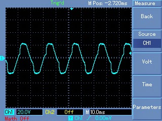
In this post I have explained a few circuit concepts which can be employed for converting or modifying any ordinary square wave inverter to a sophisticated sine wave inverter design.
Before studying the various designs I have explained in this article, it would be interesting to know the factors which typically makes a sine wave inverter more desirable than a square wave design.
How Frequency Works in Inverters
Inverters basically involve frequency or oscillations for implementing the boost and inversion actions. The frequency as we know is generation of pulses at some uniform and calculated pattern, for example a typical inverter frequency may be rated at 50Hz or 50 positive pulses per second.
The fundamental frequency waveform of an inverter is in the form of square wave pulses.
As we all know a square wave is never suitable for operating sophisticated electronic equipment such as TV, music players, computers etc.
The AC (alternating current) mains that we acquire at our domestic mains outlet also consists of pulsating current frequency, but these are in the form of sinusoidal waves or sine waves.
It's normally at 50Hz or 60Hz depending upon the particular country utility specs.
The above mentioned sine curve of our home AC waveform refers to the exponentially rising voltage peaks which constitute the 50 cycles of the frequency.
Since our domestic AC is generated through magnetic turbines, the wave form is inherently a sine wave, so doesn't require any processing further and becomes directly usable in homes for all types of appliances.
Conversely in inverters, the fundamental waveform are in the shape of square waves which needs thorough processing in order to make the unit compatible with all types of equipment.
Difference between Square Wave and Sine Wave
As shown in the figure, a square wave and sine wave may have identical peak voltage levels but the RMS value or the root mean square value may not be identical. This aspect is what that makes a square wave particularly different from a sine wave even though the peak value may be the same.
Therefore a square wave inverter working with 12V DC would generate an output equivalent to say 330V just like a sine wave inverter operating with the same battery but if you measure the output RMS of both the inverters, it would differ significantly (330V and 220V).
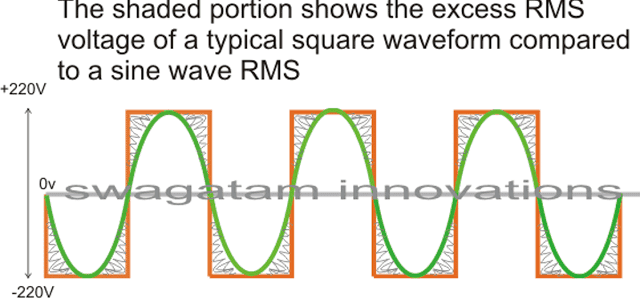
The image incorrectly shows 220V as the peak, actually it should be 330V
In the above diagram, the green colored waveform is the sine waveform, while the orange depicts the square waveform. The shaded portion is the excess RMS which needs to be leveled of in order to make both the RMS values as close as possible.
Converting a square wave inverter into a sine wave equivalent thus basically means allowing the square wave inverer to produce the required peak value of say 330V yet having an RMS just about equal to its sine wave counterpart.
How to Convert/Modify a Square Waveform to Sine Waveform Equivalent
This can be done either by carving a square wave sample into a sine wave form, or simply by chopping a sample square waveform into well calculated smaller pieces such that its RMS becomes very close to a standard mains AC RMS value.
For carving a square wave to a perfect sine wave, we can employ a wien bridge oscillator or more precisely a "bubba oscillator" and feed it to a sine wave processor stage. This method would be too complex and is therefore not a recommended idea for implementing an existing square wave inverter to a sine wave inverter.
The more feasible idea would be to chop the associated square wave at the base of the output devices to the required RMS degree.
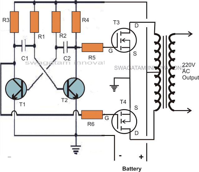
One classic example is shown below:
The first diagram shows an square wave inverter circuit. By adding a simple AMV chopper we can break down the pulses at the base of the relevant mosfets to the required degree.
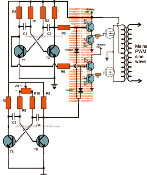
Modified square wave to sine wave equivalent inverter version of the above circuit.
Here the lower AMV generate pulses at high frequency whose mark/space ratio can be suitably altered with the help of preset VR1. This PWM controlled output is applied to the gates of the mosfets in order to tailor their conduction into the stipulated RMS value.
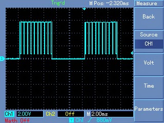
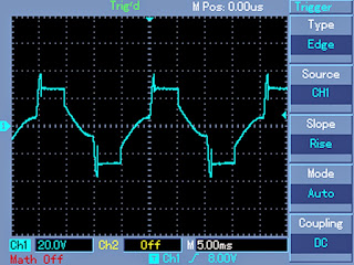
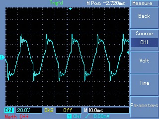
Expected typical waveform pattern from the above modification:
Waveform at the mosfet gates:
Waveform at the output of transformer:
Waveform after proper filtration using inductors and capacitors at the output of the transformer:
Parts List
R1, R2, = 27K,
R3, R4, R5, R6, R7,R8, R9, R10 = 1K Ohms,
C1,C2 = 0.47uF/100V metallized
C3, C4 = 0.1uF
T1, T2, T5, T6 = BC547,
T3, T4 = any 30V, 10amp mosfet, N-channel.
D1, D2 = 1N4148
VR1 = 47K preset
Transformer = 9-0-9V, 8 amp (specifications must be selected as per the output load for correct powre optimization)
Battery = 12V,10AH
Getting Better Efficiency Rate
The above explained conversion or modification will provide around 70% of efficiency with the achieved RMS matching. If you are interested in getting better and precise matching then probably a an IC 556 PWM waveform processor would be required.
You would want to refer to this article which shows the principle behind modifying a square waveform into a sine waveform using a couple of IC555.
The output from the above mentioned circuit can be similarly fed to the gate or the base of the relevant power devices which are present in the existing square inverter unit.
A more comprehensive approach may be witnessed in the this article where an IC 556 is used for extracting precise PWM based modified sine wave equivalents from a square wave sample source.
This waveform is integrated with the existing output devices for implementing the intended modifications.
The above examples teach us the simpler methods through which any existing ordinary square wave inverter may be modified into a sine wave inverter designs.
Converting into an SPWM
In the above article I have explained how the waveform of a square wave inverter could be optimized for getting a sine wave kind of waveform by chopping the square wave into smaller sections.
However a deeper analysis shows that unless the chopped waveform is not dimensioned in the form of SPWMs, achieving a proper sinewave equivalent may not be possible.
To satisfy this condition an SPWM converter circuit becomes essential for carving out the most ideal sinewaveform from the inverter.
The basic idea is to chop the output power devices with sine wave pulse width modulation, so that the power devices force the transformer winding to also oscillate in the SPWM mode and ultimately generate an optimized pure sine wave at the secondary side. The magnetic induction of the pulsed SPWM across the transformer winding finally gets the shape of a pure sine wave due to the inductive filtration of the transformer winding.
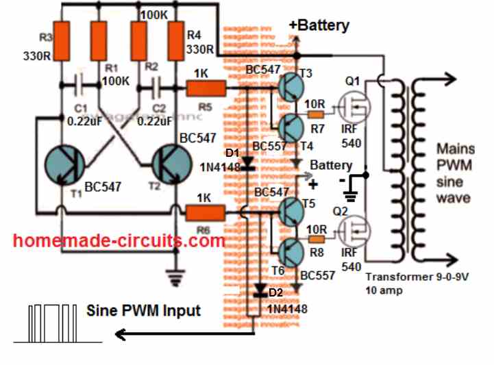
The following diagram shows how this could be effectively implemented with the concept discussed above.
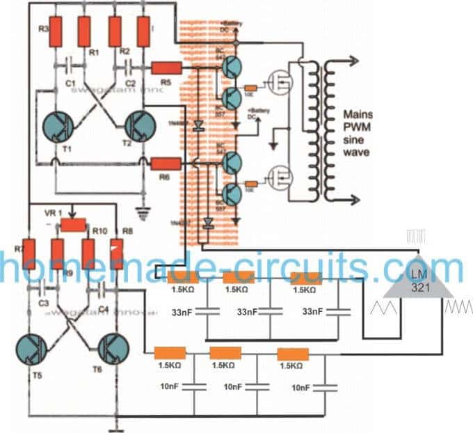
Through one of my earlier articles we understood how an opamp could be used for creating SPWMs, the same theory could be seen applied in the above concept. Two triangle wave generators are used here, one accepting the fast square wave from the lower astable, while the other accepting slow square waves from the upper astable and processing them into corresponding fast and slow triangle wave outputs, respectively.
These processed triangle wave are fed across the two inputs of an opamp, which finally converts them into SPWMs or sine wave pulse widths.
These SPWMs are used for chopping the signals at the gate of the mosfets which ultimately switch the waveform over the connected transformer winding for creating an exact replica of a pure sine waveform at the secondary side of the transformer through magnetic induction.
Love says
Can not perfect trafo design affect the waveform.
Petros Chris says
hello mr Swag,
I found your site from Google. A lot of stuff here, it is very good!
I know that the Square Waveform inverter needs a classical iron (50hz) transformer to work.
I have a dumb question.. do a spwm inverter (which pwm frequency is for example 1 khz) also need
a classical iron transformer OR it needs a ferrite toroid transformer.
I am confused because of the pwm’s high (ralative to 50hz) frequency.
thank you mister!
Petros Chris
Swagatam says
thanks Petros, you may be right, 1 kHz could cause problems for an iron core trafo, in that case you can reduce it to around 200Hz or 300Hz
Petros Chris says
thank you sir for your quick reply.
sara says
i want a design of a modified sine wave inverter in matlab simulink
Steve says
Thank you very much Sir for the thump’s up and for replying me. The issue is that am using a stabilizer container to cover the inverter…thus it wount contain upto 24(12pairs) of IRFP150N because the Vero Board will be too long. I learnt there are higher IRFP MOSFETs, but i dont know the numbers and how many watts they dispense that give 3kva with lesser pairs.
Swagatam says
Hi Steve, no need of ding 12 pairs of mosfets, if you use 24V as the supply, just 3 mosfets on each channel will be enough..
Steve says
Ok sir, but 3 MOSFET of IRFP150N will only give me 750watts. I need the specification of 3or4 pairs of MOSFET that can give me upto 3kva, please Sir.
Swagatam says
Steve, if you intend to use the mosfets without heatsink then it will 250 watts each…but with heatsinks, they will be 40 x 24 = 960 watts each according to me.
Emmanuel Etim Offiong says
Used two pair RU190N80 in each Chanel and it can handle up to 5kva load
Steve says
Good morning Sir, ive successfuly built a 1000w inverter with a 24-0-24 to 240v transformer, using a 4pair IRFP150N MOSFET for the Power Stage and its working well. I need to build another 3000w inverter but if i use the IRFP150N MOSFET it will be too long and ridiculus, so please which MOSFET can i use that will make it easy? Thank you Sir
Swagatam says
That’s great Steve, appreciate your efforts.
you can use IRFP150N mosfet for achieving 3kva, without any problems, it won’t be an overkill..
if possible please send me a small video clip of the working inverter which you have made to my email…I’ll be grateful!!
my email is homemadecircuits @ gmail.com
Solomon says
Hello sir, i asked some questions in one of ur post and i see no reply, let me ask u the same questions here:
1. In choosing or selecting MOSFETs, what must i consider, is it the volt or the amp of the MOSFETs?
2. Can i use stabilizer transformer to connect with my inverter circuit?, or does a stabilizer and inverter has different pattern of winding
Swagatam says
I have already answered them under the other post
Mehedi shakhawat says
Sir I hv some questions-
1. instance of ( R1,R2,R3,R4,R5,R6,T1,T2,C1,C2 the 50Hz oscillator circuit)
can I use a 4047 oscillator with 50-60Hz?
2. instance of (R7,R8,R9,R10,C3,C4,T5,T6,VR1 the pwm circuit) can I use a 555 PWM circuit?
3. I want to make 4047 for oscillator, with 50-60Hz and then can integrate 555 PWM with it as like as u shown the 2nd circuit, is it possible?
4. if possible then what ll be 555 PWM frequency?
sir plz make me understand
Thank u
Swagatam says
Mehedi,
yes It is possible, a few of my other designs have already used the same principle which you are referring to.
Mehedi shakhawat says
So of it is possible then what will 555 PWM frequency at pin 3 of 555? plz make it clear
Swagatam says
frequency can be anything between 400Hz and 700Hz, but the PWM must be set correctly to get proper output
Mehedi shakhawat says
ok I understand bt can u give me any suggestion for proper 555 PWM circuit? one more thing can I drive 555 ic directly from 12volt 9amp battery? is it need to any regulator for 555 ic, if need then what volt regulator need?
Swagatam says
you can use the 555 section from this article
https://www.homemade-circuits.com/infra-red-ir-led-flood-light-circuit/
if your 12V is constant then 9amp will not matter, you can use it for the 555 circuit.
manash Athparia says
Is the second diagram is a pure sine wave or modified sinewave inverter
Swagatam says
no it is not pure sine but it is an improved modified sine
manash Athparia says
Can I expect same sine wave output if I connect 555 pwm with the first square wave circuit?
Swagatam says
where exactly do you intend to connect??
manash Athparia says
Maybe a laptop adapter
Swagatam says
I was referring to the following statement, could not understand this:
“…if I connect 555 pwm with the first square wave circuit?”
manash Athparia says
The first circuit with two bc547 and two MOSFETs
Swagatam says
yes it is actually possible! you can hook it up directly with the gates of the mosfets.
afsal says
Sir please help me to convey the details regarding the conversion of 12 volt 50 hz square wave signal to 12 volt 50 hz sinusoidal wave…pls help me in the designing part ,
Swagatam says
Afsal, you can achieve it through a suitably dimensioned L/C integrator circuit.
Nataneil says
I know that when using only n channel mosfet for full bridge inverter the mosfets on the high side must be higher than the voltage applied to the drain. How can that be achieved? Can I parallel them for more power instead of using one set of mosfet for switching?
Swagatam says
paralleling will increase the wattage handling capacity, it won’t help the bootstrapping implementation.
SODIQ ENIOLA says
Hi Swagatam Sir
I implemented one of your CD4047 circuit and I’m having a good square wave at the output
But I want to make it a square wave to be suitable for all appliances
I tried to use three pole RC as filter but it doesn’t really work
I tried a low pass filter but only one of the two waves is giving a trapezoidal pattern
I want to try a bandpass filter but I don’t know which OpAmp to use
Can you please give me a link to a circuit of any filter that you believe will work perfect or even a complete Sine wave circuit
Thanks for always being there Sir
Swagatam says
Hi Sodiq, the RC filter shown in the last circuit is a square wave to triangle wave converter, and it is a proven design, and therefore it has to work. Please check the RC stage separately using different frequencies and try adjusting the RC part values by some trial and error until you get the desired triangle waveform.
Nataneil says
Sir I am Nataneil a new person on your site. I am seeking help to build a 24v input fullbridge inverter. I have only irfz46n n channel mosfets for the high side and low side, a cd4017 ice, lm555 timer ice. I need to know how do I increase the voltage for the high side and to how much voltage.
Swagatam says
Hi Nataneil, you can increase the voltage by configuring the IC 555 output with a voltage doubler stage….if possible I’ll try to include it as a new post in my website soon, alternatively you can try implementing the concept which is explained in this article:
https://www.homemade-circuits.com/2017/03/sg3525-full-bridge-inverter-circuit.html
but since this concept is researched from various online sources I cannot guarantee its working.
for a foolproof results, you can perhaps go with a specialized design as given below using IC.
https://www.homemade-circuits.com/2014/01/simplest-full-bridge-inverter-circuit.html
Aabhishek Sharma says
Hi sir, I'm now double stressed, I, this time recently checked only the square wave part of circuit with my old 12-0-12 5amp transformer and this time I got 266v even without pwm, I really think that the circuit and 555pwm have damaged both of transformer now what to do? This time life sucks ?.
Aabhishek Sharma says
Hi sir, every thing else is going good now but the LEDs are still fusing because of high voltage 260v(without load) as you know with loads it's 230v in mine case (refer to upper comments) and I can't use 9-0-9 transformer because I had bought 12-0-12 10A far earlier, and the voltage problem is also due to that reason I know. So what to do now? Can I use a converter shown in your blog (anyone from your blog) for 12v to 15v? Is it safe I'm positive towards this regard, please read full and reply soon.
Swagatam says
Hi Aabhishek, to control high voltage you can add the following circuit to your inverter and see if it helps.
https://www.homemade-circuits.com/2014/01/automatic-output-voltage-regulator.html
Aabhishek Sharma says
Hi sir, could you please help me with some other idea with this matter. Read older comments for revising summary of problem. Please let me know if you have any help for me
Aabhishek Sharma says
I'm using 12-0-12 10A as I couldn't buy a new 9-0-9
Swagatam says
there's no other idea, either you use the 741 circuit which is suggested to regulate the output, or change the trafo.
or alternatively you can buy another 12V battery and put in series with your present battery to get 24V and use this 24V with your 12V trafo…then adjust the PWM to get 240V at the output
Aabhishek Sharma says
Hi sir ???new problem arised, today I checked my circuit without pwm(only square wave circuit) and multimeter was showing 595v to 600v output and then by connecting pwm I tried it to adjust then it showed "1" means limit crossed. Earlier this problem was not there why is it happening even without pwm, and also with pwm. This problem happened only today, please tell me what is wrong now. I'm littrally very stressed ?, this was my holiday project and holidays are going to be over.
??☹️my electronics role modal please help me. Please.
Swagatam says
Hi Abhishek,
make sure the PWM frequency is not over 200 or 300Hz.
for your 600V issue you can read the following article.
https://www.homemade-circuits.com/2017/07/inverter-voltage-drop-issue-how-to-solve.html
and please don't comment under this article because it is flooded with comments and I have to press "load more" button repeatedly…you can comment under some other inverter article
Aabhishek Sharma says
Sorry sir, I'm commenting again here but sir firstly I tested it without pwm then I tested the same transformer with my another square wave inverter then output was 360v. And I think this setup have damaged both of my transformer as I tested old 5amp transformer 12v then also the output was 260v, because earlier I had tried both of my transformer with this setup using pwm also and I think my both transformer are now damaged due to this full set (may be high frequency done this damage) please help, and can we have a video call so I can make you understand more easily.
Aabhishek Sharma says
Hi sir, my transformer is of good quality it's made by shopkeeper on order its big and weighs 8kgs, sir yesterday I added new mosfets and increased them in parallel but when tested no output was there (fluctuations) only some stabilizer like abnormal sound comming when I removed then also conditions were same,I'm very stressed.I think may I'm these problems are because I'm using zero pcb (pcb with square boxes and predefined holes) and not the copper claded, and also due to some improper soldering, because transformer is good. I have written thanks because everytime you give true knowledge and guidance. PLEASE reply soon.
Swagatam says
Hi Abhishek,
if transformer is good then it should take the load. and the voltage should not drop…. I am sure something is not correct in your circuit or the parts which I cannot identify from here.
adding mosfets will not help at all, because it's not correct ,a single pair of IRF540 can handle upto 200 watts to 500watss easily.
try with BJTs if you are not able to use mosfets…try with TIP142 instead of the mosfets
Aabhishek Sharma says
Hi sir, can you please tell me how much watts power a samsung 32inch led tv consumes?
Swagatam says
I have no idea about it, you may find it behind the TV
Aabhishek Sharma says
Hi sir I have replaced the lower pwm with 555pwm as you advised and it's good. I have adjusted it without load on 240v but when I connect 3 Watt incandescent bulb the output dropped the voltage by multimeter was 178.so how to adjust it whether while adjusting I have to also connect a load then the voltage without load must come upto near 300v what to do master.
Swagatam says
Hi Aabhishek, since this is a simple circuit and does not employ any load control circuit, therefore the best way to adjust the PWM is by connecting the load, and anyway the voltage which you may see in your meter without load may not be correct, because the meter will always show a much higher voltage without load due to its high impedance nature, therefore the best way is to adjust the preset with a load connected, and remember I had told you to use a 9-0-9 trafo, at 10 amps and a 12V 7 to 10AH battery fully charged.
Aabhishek Sharma says
Hi sir, now I can power mobile charger and 3w bulb (tested) on inverter but when I connect 7w LED bulb the bulb is not glowing and frequency sound increases.what to do sir?
Swagatam says
Aabhishek, something is not correct in your circuit, it seems the trafo is not saturating correctly, and this can happen when either the transformer or the battery or both are not matching correctly.
when you connect ammeter in series with the battery the meter should show a current equivalent to the load current.
Aabhishek Sharma says
Hi sir I think led bulb might be fused due to high voltage 260v ac, when i connect 3w bulb the voltage goes to 230v and when connecting my phone charger then voltage drops to 215 v what to do? Is there any way you can suggest so I could use this inverter as a good inverter with no further problems or issues. PLEASE HELP. So finally I can say you thanks for this project.
Swagatam says
Hi Aabhishek, LED bulb are rated to work with 285V so it cannot fuse at 260V.
Your transformer is not taking the load due to lack of amps, change the transformer with a good quality heavy duty transformer…in todays market most transformers are falsely labelled…for example 3 amp trafo can be seen labelled as 5 amp…no need of saying thanks
Aabhishek Sharma says
Hi swagatam sir, is it possible adding mosfet in parallel with reducing the chances of MOSFET damage and also reduces mosfets heat?
Swagatam says
You must first find out why your mosfets are burning if it's due to overloading then you can you can add parallel mosfets, but I don't think it's due to overloading.
I hope you are my following my suggestions and not doing just anything haphazardly???
Aabhishek Sharma says
Hi sir, I want to ask that is it possible that while adjusting preset the mosfets can damage. https://plus.google.com/+AbhishekSharmatechperson/posts/9PNR5Rfx2Rm this is image link for pwm circuit.
Swagatam says
No that's not possible, in your mosfets can get damaged due to a duplicate mosfet, static electricity from your hands, wrong pin connection, drain short circuit or perhaps from reverse transformer emf if diodes are not connected
Aabhishek Sharma says
Hi sir, today I checked the circuit without pwm it was working good without pwm but now I used it with pwm then for some seconds voltage was upto 175v and then without adjusting it reached 201v and mosfets were hot (heat sink is used) and smoke was comming. PLEASE HELP. https://plus.google.com/+AbhishekSharmatechperson/posts/AndSBSBEkVh link for modified circuit as I'm not using bc547 and 557 STAGES.
Swagatam says
Hi Abhishek, the buffer stage BC547/BC557 was specifically introduced to keep the mosfets safe, but since you were having difficulty in configuring them therefore I allowed you to try without it…but I think it should be included, so better put it back in place as shown in the diagram, I'll update the diagram soon and make the stage simpler by removing the extra diode at the emitter of the BC547.
And remember you shoold NOT make the design on a breadboard…use a strip-board and make it by soldering…
Aabhishek Sharma says
Hi sir.,ok I will do it again and I'm using zero pcb and always solder, no breadboards!. Hope doing this will help, sir I really respect you and your knowledge you are like my favourite teacher.
Aabhishek Sharma says
Sir in my PCB there is no space to put those bc547 and 557 STAGES, so what to do I really want to make this inverter Perfectly working. PLEASE HELP ME sir.
Swagatam says
Thanks Abhishek, how can I help you if there's no space in your PCB??
replace the lower oscillator with a IC 555 PWM oscillator as shown below
https://3.bp.blogspot.com/-L9gXRB3GcDc/Vvek1mJUGOI/AAAAAAAANZE/ocPbYVXjnQMDKpxwDB0sd2fu5uqlJkutw/s1600/pwm%2Bcircuit.PNG
connect the output pin#3 with the PWM diodes associated with the mosfet gates
Aabhishek Sharma says
Hi swagatam sir again problem even with the modified version of this inverter (see last comment) which you approved when I removed mosfets it was giving 300v output without using pwm circuit but the transistors in first oscillator were becoming hot so you suggest me an alternative, and I have changed mosfets 2 times from starting day and till now. Working without mosfets. Im using 12-0-12 10A transformer and 7.6ah battery. See last conversation for circuit and tell me an alternative this is first time I'm having problems in making something. I'm using 12-0-12 10A transformer.
Swagatam says
Hi Abhishek, this is such an easy circuit, not sure why you are getting so much of problems, may be because you are doing it without understanding the concept, or using damaged parts.
By the way who told to remove mosfets??? how can you drive the transformer without the mosfets??
I am not able to understand what exactly you are doing….
I would advise that you first thoroughly understand the working of the two circuits and all the parts and only then proceed.
Aabhishek Sharma says
Hi sir,
Can I use transistor Darlington pairs instead, of irf540. May be the seller from whom I take irf540 has given damaged mosfets.
Swagatam says
Hi Aabhishek, yes you can definitely do that, that's what I had recommended you earlier…..you can use 2N2222 and 2N3055 in darlington mode…or any other similar combination will do
Aabhishek Sharma says
https://plus.google.com/+AbhishekSharmatechperson/posts/RH3rnQjRYLm please check the circuit in link, I have less time.
Aabhishek Sharma says
Please sir reply fast, check this link circuit
https://plus.google.com/+AbhishekSharmatechperson/posts/RH3rnQjRYLm
Swagatam says
abhishek, I have already answered you…your diagram is incorrect…you must use two separate diodes from the gates just like you did in your previous BJT based circuit.
I hope you have understand this time.
Aabhishek Sharma says
Hi sir, I made new circuit, you may please see this and suggest
https://plus.google.com/+AbhishekSharmatechperson/posts/RbQWxq8bZoD
Swagatam says
PWM diode is correct, however the 1K and the 1n4148 can be removed…you can directly connect the gates with the cpllector of the transistor
Aabhishek Sharma says
Hi sir, I think you haven't focused on my question, I WAS ASKING " can I make this modified sine wave inverter by not using the upper bc557 and bc547 stages, diodes and all, by using the main upper AMV and lower pwm, and mosfets, no bc557 and bc547 stages , as these things are creating complications." * I MEAN IF I REMOVED THE BC547 AND 557 STAGES AND JUST USING UPPER (MAIN AMV) AND LOWER PWM AND MOSFETS ONLY. PLEASE REPLY FAST TILL AFTERNOON PLEASE MO ?.
Swagatam says
that is what I exactly suggested…use the first circuit in the above article which has used only mosfets no BJTs….you can integrate the PWM directly to the gates of the mosfets
Aabhishek Sharma says
Hi sir, how to connect, I mean only one side of pwm output is connected to only one MOSFET gate, if it's not clear please check link https://plus.google.com/+AbhishekSharmatechperson/posts/RH3rnQjRYLm
Swagatam says
Abhishek, do exactly as you did in your previous circuit…using two diodes, it is so simple.
Aabhishek Sharma says
Hi sir, when I test pwm, with 16v supply separately, it's out put is 6v,ac,and the output can only be measured when I connect only one prob of multimeter to the capacitor output , when I connect both probes output on screen is 0v, is this normal,?
Another question is that only lower circuit is said to be pwm or the upper bc 547 and 557 and 1n4007 circuit also a part of pwm
Swagatam says
Abhishek, your method is incorrect. You must connect the meter probes across the collector/emitter of the transistor…and the meter should be in the DC range NOT AC range. and the measured volatge must vary from some minimum value to maximum value in response to the pot rotation.
The Bc547/557 is not in the PWM section.
you can try the first circuit from this article…connect the LEDs and see the effect of the PWM on the LEDs..if it illuminates from fast to slow and vice versa then the circuit working OK.
after this you can reduce the capacitors to 1uF for fast PWM..
https://www.homemade-circuits.com/2012/01/how-to-make-any-light-strobe-light.html
Aabhishek Sharma says
Hi sir, one question can I make this modified sine wave inverter by not using the upper bc557 and bc547 stages, diodes and all, by using the main upper AMV and lower pwm, and mosfets, no bc557 and bc547 stages , as these things are created complications. Please reply as as possible.
Swagatam says
You can try it as shown in the first diagram, make sure to use 1K for the gate resistors and put 1N4148 diodes parallel with these resistors in the following manner:
1.bp.blogspot.com/-IJ69-6jHAI8/UjGwaj9sxVI/AAAAAAAAFOY/vdqUBesdFqA/s1600/how+to+prevent+mosfet+from+burning.png
Aabhishek Sharma says
Hi sir, yesterday night I tested my above circuit by 12v battery for adjusting the 50k preset with multimeter connected at output of transformer, so in first round the voltage was going on decreasing from 210 to 90v ac, In 2nd round the output was 250v and suddenly the point where I had connected the negative terminal catches sparking and fuse burnt,so I removed and again connected battery negative (to point where pwm -ve, oscillator-ve and both sources of MOSFET were connected together) but again that point shorted sparked. I'm using pcb (not printed one), can you assume what is problem or which part should I check. Please help me
Swagatam says
Abhishek, sparks should never come,,,it means there's a short-circuit in your circuit or something is not working correctly.
first make the basic circuit without the PWM….and make sure it produces 250 to 300V and is able to illuminate a 60 watt bulb very brightly.
after this check the PWM circuit with a DC voltmeter connected across collector/emitter of any one of the transistors…the Dc V must change as you vary the 50 pot. also confirm the frequency of the PWM with a frequency meter.
If you are having problems with a transistor oscillator you can replace it with a IC555 PWM circuit which is much easier to adjust
Aabhishek Sharma says
Hi sir, I removed the second AMV circuit and checked everything in first upper circuits for shortings using multimeter I found in one MOSFET source and drain of that mosfet beeped, while in other this was not happening, so I think shortings of source and drain shows that mosfet is faulty, so replacement of one MOSFET will be OK or I replace both, how to protect new mosfets from further defects. Please reply fast. I'm really interested in making this inverter perfectly working.
Swagatam says
You can refer to the following article for learning how to protect mosfets
https://www.homemade-circuits.com/2013/09/mosfet-protection-basics-explained-is.html
if your mosfets are duplicate then cit cannot be protected.
you can replace them with BJTs if you are unable handle mosfets
Aabhishek Sharma says
Hi sir the link you sent is seen and understood but I want to ask that after replacing MOSFET, now can I check the inverter or I need to give some protection to the mosfets, which diodes can I use with mosfet to protect them. Can I test inverter without providing any diode protection to mosfets.
Swagatam says
Abhishek, although all mosfets are protected internally with diodes, still you can place diodes across the primary of the trafo… from center tap to the outer taps..cathode will go to the center tap, and anode to the outer taps…you will need two diodes from ceter to the outer taps.
1N4007 diodes can be used for the diodes.
Aabhishek Sharma says
Hi sir, every time you are so helpful, I want to ask that can you explain the procedure for adjusting preset (50k I have used) without damaging any thing. PLEASE HELP ME, tell me a safe method. How to adjust it.
Swagatam says
Hi Abhishek, the procedure is simple.
initially keep the preset slider at the center.
Now switch ON the inverter and connect an AC voltmeter at the output of the transformer for measuring the voltage.
after this slowly adjust the preset until the output voltage settles down to 220V.
I hope you have used a lower rated 6-0-6V or 9-0-9V trafo for a 12V battery
Aabhishek Sharma says
Hi sir, I'm using 12-0-12 10A,transformer for 12v 7.6ah battery. Is it OK? Will the circuit work perfectly. OR any correction I should make. PLEASE REPLY FAST.
Swagatam says
12-0-12 will produce 180V output with PWM activated…you will have to use a 6-0-6 10 amp or 9-0-9 10 amp trafo for getting proper results
Aabhishek Sharma says
Hi sir, I only have 12-0-12 10A transformer, you must have specified in article that it's necessary (mandatory) to use 9-0-9 v transformer this is very disappointing.Now the problem is budget and I already spent rs 1050 on that transformer, shopkeeper will also not take that back because it was made on order, can you please tell me a solution so I could get 220v to 230v AC from the same transformer i.e 12-0-12, should I increase input if yes, how? Please help, I couldn't ask my parents for this. PLEASE HELP.
Aabhishek Sharma says
Hi sir, please reply fast,can I use 820pf capacitor instead of 680pf, and 50k preset instead of 47k in second circuit, because 680pf capacitor are not available in market. And tell me how to adjust the preset and from where to measure the rms to adjust preset, explain me whole process please. PLEASE HELP ME.
Aabhishek Sharma says
Hi sir, I'm using 50k preset (not the potentiometer) and 820pf capacitor instead of 680pf capacitor, is it OK? How to adjust the preset, what is the process.
Swagatam says
Hi Abhishek, yes those are OK will do!
for confirming the frequency you can take the help of the following software
https://www.homemade-circuits.com/p/transistor-astable-multibivrator-amv.html
Aabhishek Sharma says
Hi sir,
Can you tell me how to connect preset in this as the circuit shows,all three terminals are connected at different places, I don't know how to connect, can you please assist me through any image or photo explanation, please reply fast.
Swagatam says
Hi Abhishek, the arrow symbol indicates the center pin of the preset and the outer two points correspond to the outer two pins of the preset…
Aabhishek Sharma says
hi sir,
please tell me how to tell shopekeeper if want transformer for 100 to 150 watts inverter? ,as if i say them i want 12-0-12 10A transformer they say tell us "va" .thay dont understand me,tell me what should i say them in their language if i wat transormer for 150w inverter ?
Swagatam says
Hi Abhishek, If they are asking for VA, then tell them the value by multiplying 12 x 10 = 120 watts….. there's nothing too critical about it….
Swagatam says
Abhishek, those are not Darlington pairs, those are arranged to generate a push pull action on the mosfet gates…they are in NPN/PNP formation
Abhishek Sharma says
hi swagatam sir ,can you elaborate about circuit shown in link
http://www.theengineeringprojects.com/wp-content/uploads/2012/11/H-Bridge-Circuit-1.jpg and 1.from where should i take output
2.what kind of transformer is used.
Swagatam says
Hi Abhishek, you can feed the mosfet ends with any push pull frequency source such a from a 4047 IC, a SG3525 IC or IC 4017 etc
Abhishek Sharma says
Hi sir what is the value of the transformer used (in amperes) in the link
http://www.theengineeringprojects.com/wp-content/uploads/2012/11/H-Bridge-Circuit-1.jpg and can I replace all mosfets with irf540. And can I use centertap instead?
Swagatam says
the trafo value will depend on your choice of output voltage and current and also the battery specs, just as we do for push pull inverters.
center tap cannot be used, for center tap you won't require a H-bridge circuit you can simply use a 4047 type IC for it
DareDiamond says
Please Sir, How Can I make the the Frequency Of this Circuit Variable?
Swagatam says
By changing R1/R2
Ehtesham Nisar Ahmed says
Thanks for posting such a nice and useful project.
I want to make an inverter of 1000-Watts or higher, could please guide me what components mainly required
Best Regard
Swagatam says
I have already posted a related circuit in this website, please use the search box to find it.
Aminu Yahaya Ibrahim says
Sir, I have already built this inverter. But, It is sometime giving above 230v output, depend on the battery AH I use.
Colud you help me with any output filter, so that the out will be constant at 220v to 230v?
Thanks
Swagatam says
Aminu, it is not required as long as the output is between 210V and 240V, it is quite normal.
If you add an output regulator it will make your design unnecessarily complicated
Eric Pugh says
Hi there, I have read over your blogs and am very impressed with your electronic knowledge, I have a question for you, I will be running two dc to ac inverters rated at 10,000 watts surge and 5,000 watts constant running watts each. They are however MSW ( modified sine wave) I am wondering if there is a circuit I could build for each of these that could convert them more closely to a standard sine wave to make them safer for use for sensitive electronics ETC, computers, tv,s video games and the like? I am familiar with basic and communication electronics but rather weak when it comes to inverter modifications. the inverters are a HF( Harbor Freight) product that carry the CEN-TECH brand name. I havent been able as of yet to find a schematic for these units. It would be greatly appreciated for any help you could offer…thank you in advance
Mad Scientist
Swagatam says
Thanks Eric, It is definitely possible using the concept explained in the above article, however first you will have to figure out how the mosfet stages are configured in your existing inverter, and then target the right mosfets for integrating the explained circuit theory…otherwise you may end up ruining the entire inverter or create catastrophic results.
You can also try a much improved version using SPWM which I may soon present in one of my future articles in detail. In the meantime if you need any help you can feel free to consult me
SHADAB RAZI says
Sir can we convert 230v square in to 230v sine wave directly please help me out
Swagatam says
you can convert 330V square wave into 220V sine wave using SPWM,
john omaba says
Good day sir, the VR has two legs or three legs. Bcos the one i have is three legs but the one on diagram is just end to end with the transistors. Thanks
Swagatam says
all presets and pots will have 3 legs
Rahul anymation says
what is freq of oscillator?how to calculate?
Aminu Yahaya Ibrahim says
Yes Sir, it has.
But what I mean is this, UPS works on little corrent battery i.e 7ah and it's able to operate a computer that needs high watts ?while majority of inverters cannot.
I learn this due to the suggestion you made to start our homemade inverter with big ah battery ? e.g 100ah or 200ah to operate 100 watts which is not as big as deck top.
thanks you Sir.
Swagatam says
your assumption is not correct, an inverter can be equally efficient just like an UPS as far load handling is concerned…except the waveform and automatic functions which are the more enhanced in UPS.
please show me where did I say that a 100 watt load would require a 100 AH battery??
Swagatam says
A 100 AH battery will be required for a 100 watt load if a back up of 10 hours is expected….so I might have said on that context.
Aminu Yahaya Ibrahim says
Sir this is Aminu.
Sir I wonder why UPS can operate computer ? using a 12v 7ah battery ? while inverter cannot work with such a higher watts device on 12v 7ah.
Swagatam says
Aminu, an UPS also has a built-in inverter so that's a wrong assumption.
without an inverter the UPS cannot create the back up supply
Carmen B Gavin LATA says
Hi friend I like your projects. I actually want to build and try your design. So, for the first circuit in which you used two power mosfet , can i replace them with IRF150n? If so, what will be the output power. And also kindly tell me if i use IRF150n with the second schematic contains four transistor what will be the power then? Thanks. You always helped me alot.
Swagatam says
Thank friend, the output will depend on the wattage rating of the transformer and the battery AH capacity…the mosfets rating should be selected such that they are able to comfortably handle the power consumed by the transformer and the connected load.
only the mosfets are responsible for power delivery, other transistors are only for buffering they need not be changed
middle east says
Sir
I have su-kam inverter trusty . 1500 w . 24 v .when connecting to home all fans making noize . What should i do to remove that noize from fans . Shall i add capcitor to the out put . If yes which type and size
Thanks
Swagatam says
yes you can try it…..you can see the following example design and follow the configuration:
4.bp.blogspot.com/-khKat0UA8Jw/UITpCnNd7yI/AAAAAAAAA_A/8x-KAD2aHLE/s1600/simplest60+Hz+Inverter+circuit+diagram.jpg
Akshay Rathore says
I would like to know if this circuit has been implemented and tested as i am experincing some problems and would like to brain storm for possible rectifications from those who have implemented this exact circuit.
Aminu Yahaya Ibrahim says
Sir what I mean is that, If I used the 2nd circiut the fan is not operating but the circuit can operate many appl and If I remove PMW part and leave AMV and BC547/557 the result is the same. whhile with the first circuit (squar wave) that has no bc547/557 stage, the fan can work with little noise.
Swagatam says
Aminu,
connect a 60 watt incandescent lamp to the inveter output and check its brightness with PWM ON, and without PWM, this will tell you whether or not PWM is reducing the output power?… and why the fan may be finding it harder to rotate with the PWM ON.
Aminu Yahaya Ibrahim says
Sir,
I did it.
I used this ic555 configuration, as you suggested me alias.
http://www.www.homemade-circuits.com/2012/05/making-adjustable-electromagnet-circuit.html?m=1
After I connect this to the AMV, I can vary the volt from 0. to 220v and above.
I dont realy know if, my circuit is faulty or not.
I tried many electronic app and they work, But the fan is still incline to operate.
I wondar why, the First circuit (Square wave) can operate the fan with little noise, While if I connect the PWM part (including this newly adopted i.e IC555 part) it woun't operate.
Anyway, Sir, Your help is always appreciated and Iam very much proud of you Sir.
Thank you once again.
Swagatam says
Aminu, the PWM is chopping the actual 50 Hz, that means it is actually reducing the overall power….so this in turn means that the transformer needs to be more powerful for a PWM inverter because the PWM is cutting off 50% current…so this could be the issue…try another trafo with higher wattage and check the response.
Aminu Yahaya Ibrahim says
Ops, Iam wrong Sir.
The volt is not 220-240 its almost 200v peak and almost 195v the low, so, its not stable. It is shaking ups and down within a second.
This is why the multimeter is reading wrongly.
Swagatam says
Aminu as long as you don't confirm the lower circuit performance you'll always be in doubt regarding the circuit proceedings, I think you should try replacing the lower AMV with a 555 IC AMV, I'll try to update the modification soon in the article, may be tomorrow, you can then try it out and check the response.
Aminu Yahaya Ibrahim says
I did it Sir,
But the test is done with 0.2uf i.e 224j instead of the one you suggested, because I have only a pair of 104 which was used in PWM.
Based on this test i can see the volt is ok, Its around 220 to 240 now with PWM but I tried to adjust the pot and nothing change even if the pot turned to the end of each direction.
But I load only 26watts economy ligh bulb.
Aminu Yahaya Ibrahim says
Ok Sir,
I will try it and update you with the result as soon as possible.
Thank for the help Sir.
Aminu Yahaya Ibrahim says
Sir,
Right now I do some changes as follows,
I used 7.2_0_7.2 tranfo 650Va.
I chanced mosfet to IRF3205.
I removed pwm.
finaly, the fan operates with some low noise if compared with my last test.
and if I connect pwm part, the fan fails to operate and produce louder noise.
Thank very much, its few staps remain to build a very reliable low cost inverter.
Swagatam says
Aminu,
PWM will reduce the RMS of the output voltage therefore the transformer's primary rating should be lower than the battery voltage, 7-0-7V is a good trafo but its current should be at least 10amps, and for higher loads the battery AH should be at least 10 to 20AH fully charged.
If the PWM frequency and duty cycle is high, the fan will make noise, so adjust it until the noise is almost gone.
reduce the lower AMV capacitor values to 0.1uF to reduce the frequency and adjust the pot to optimize the duty cycle, and then see the response.
Aminu Yahaya Ibrahim says
Sir,
with pwm the AC output volt is between 180v to 111v or even lower, but without pwm the volt is alway above 200v AC.
I used three transfo
1. 7.2-0-7.2 transfor removed from 650va
2. 12-0-12 5A
3. 500va transfor that has no details printed on it.
each showed the same result.
I used 12v 20AH battery.
Sir, The inverter has no any other problem now because I discovered them and solved them today.
But, the issue of operating Fan is still unchanced.
the fan is 50watts and its only producing loud soud without turning, even if I used my hand to help it to turn, it won't.
and this problem is the same with both oper and lower circuit.
Thank you Sir for the help.
Swagatam says
Aminu,
remove the PWM feed from the lower circuit, and check the response.
and what's the battery AH?
and what's the transformer amp rating, let me know about these, I'll try to troubleshoot.
would it be possible for you to use power BJTs instead of mosfets just for testing sake? because BJTs are much easier to handle than mosfes.
Aminu Yahaya Ibrahim says
Sir,
I am refering to this recent one that you asked me to build and I builded it. I dont mean it has problem, Iam the one coursed it.
I found the track and jumper are borning and the mosfets are getting hot instantelly when i load a higher watts. so through your help all those was solved.
base on my check I discovered the courses of the problem as follows: the battery power is set to cross over the circuit then goes to transf and it is also solved through the procedure I sent in the last mail.
Sir, still Iam exeriencing some problems that i dont know their source.
1. one of the mosfet is getting hot If i load the
laptop or any higher wattages appilience like
100watts bulb.
2. my multimeter is ok, but when connected it to
the inverter in order to test the AC output volt, the multimeter is reading wrongly and if connected to main AC its reading normal 220v or 219v.
3. still the inverter can not operate Fan.
As usual, I need your help Sir to solve them
thank you very much sir.
Aminu Yahaya Ibrahim says
Morning Sir,
The problem of component borning has been solved by following this procedure.
1. I connected the battery positive directely to the centre of transfo and then I used thin copper ware with switch to the positive input of the circuit board.
2. The negative of the battery is also directely connected to the sourse of the two mosfet then I used another thin copper ware to the board.
I think, this can save all the components in the board.
Sir, still Iam exeriencing some problems.
1. one of the mosfet is getting hot If i load the laptop or any higher wattages appilience like 100watts bulb.
2. my multimeter is ok, but when connected it to the inverter in order to test the AC output volt it is reading wrongly and if connected to main AC its reading normal 220v or 219v.
3. Still the inverter can not operate Fan.
As usual, I need your help Sir to solve them
thank you very much sir.
Swagatam says
Aminu, which inverter circuit are you referring to?, is it the above inverter or the ready one faulty inverter which you are presently repairing?
if it is the one which you are repairing, it would be difficult for me to judge and troubleshoot because I don't know what kind of circuit may be used in it and what stages may be involved…
Akshay Rathore says
and what will be the effects on the same motor load if i was to directly connect it to the output of this inverter ???
thanx for all ur help.