
In this post we try to diagnose a burnt SMPS circuit and try to troubleshoot and repair the circuit. The shown unit is a cheap readymade Chinese make SMPS circuit. This article is written as per the request made by Mr. Kesava.
My SMPS got Burnt
The below attachment is 12v 1.3 amps SMPS for charging Agriculture Sprayer..If charge full the green led will glow...If charge low the red led will glow...
But now this charge not working...And i check inside , The AC input bridge rectifier IN4007 1diode got damaged...i replace it with new one diode..Now the new diode also damaged....Pls guide me sir....
In our area shop..this type of chargers are not available sir...But my aim is not to buy new one..i itself want to rectify with u r guidance sir....Pls help me sir....
Sorry for bad english.I'm not good sir...
Thanks & Regards N.Kesavaraj
Troubleshooting the Problem
Hi Kesava,
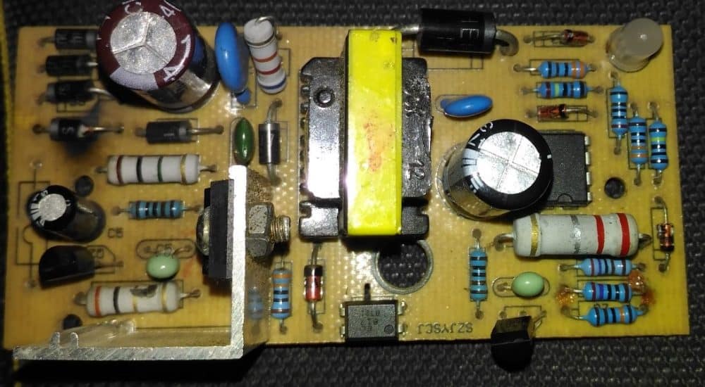
It's most probably due to a burnt mosfet, the one which can be seen on a heatsink. You can try replacing it with a new one, and also make sure to change the adjoining 10 ohm resistor which also looks like it is burnt.
Regards.


Repairing the SMPS Circuit
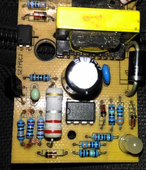
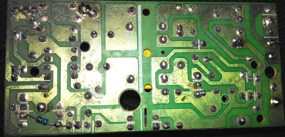
Referring to the images above, the primary side of the unit appears to be the popular 1 amp 12V SMPS adaptor using a mosfet based switching design, and includes an opamp based auto cut off charger section at its secondary section of the board
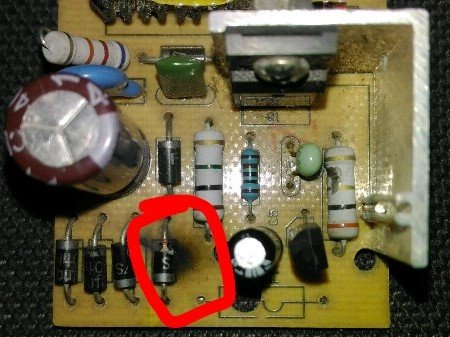
From the first two images we can clearly see that one of the diodes being completely blown apart, and responsible for shutting down the entire circuit board.
A bridge rectifier can be normally seen at the beginning of any SMPS circuit and is introduced primarily for rectifying the mains AC to a full wave DC, which is further filtered using a filter capacitor and applied to the mosfet/inductor stage for the intended flyback primary side switching operation.
This primary side switching causes an equivalent low voltage pulsating DC to be induced at the secondary side of the transformer, which is then smoothed using a large value filter capacitor at the the secondary side for acquiring the final stepped down SMPS DC output.
From the image it appears that the entire design is based on a mosfet, inductor switching topology wherein the mosfet becomes the main switching element in the circuit.
The diodes in the bridge rectifier appears to be the normal 1N4007 diodes which are capable of handling not more than 1 amp current, therefore if this 1 amp value exceeds the diodes can get ripped through and damaged.
The diode might have burnt due to a high current passage which in turn might have happened due to a stalled mofet inductor operation. Which means that the mosfet might have stopped osculating causing a short circuit through itself, allowing the entire AC to go through the components within the input supply line.
How to Repair the SMPS Circuit.
The shown burnt SMPS can be repaired with the following simple steps.
1) Remove the mosfet from the PCB and check it with a multimeter
2) Without any doubt you will find the mosfet being the faulty component, so you can quickly go for a replacement of the same using a correctly matched mosfet
3) After changing the mosfet make sure to change the burnt rectifier diode also, and ideally change all the 4 diodes in the bridge, to ensure no weakened diodes are present in the network.
4) You may also want to check if there are any other parts such as resistors or thermistor that may look suspicious and if any replace them with new ones.
5) Once all the doubtful elements are replaced it is time to switch ON the SMPS for the final verification.
However this must be done with a series protection load in the form of a series incandescent bulb to make sure that the circuit does not blow of due to some other hidden fault. A 25 watt bulb will be just good for safeguarding the unit from any catastrophic circumstances.
6) On switching on the SMPS, if the the bulb does not glow, it would probably indicate all's well and the unit has been repaired successfully. Now you can feel free to check the output voltage of the SMPS with a meter and confirm that it is producing the right readings.
7) Finally without removing the bulb connect an appropriately rated DC load and check whether it is working correctly or not.
8) If everything seems to be working normally you can remove the series bulb, and repeat the testing process, but make sure to include a small fuse in series with the input supply permanently.
9) However in case the bulb shows a bright glow, would indicate a serious problem persisting in the SMPS circuit and will need to be investigated afresh, this may be done by first switching off the unit and then checking each and every component in the primary side of the trafanformer.
10) The components which needing a recheck will be fundamentally the ones which are prone to high voltage and current damage, such as small BJTs, diodes and low value resistors.
11) The components which can be left unchecked are the ones which are adequately rated and are able to protect itself from from high voltage and current inrush. These may include high value resistors above 50K, or low value wirewound resistors above 1K.
Similarly, capacitors which may be rated above 200V can be left unchecked unless one of these look somewhat damaged externally.
Testing for a Burnt Inductor Transformer
Every SMPS circuit will essentially include a small ferrite transformer, which this part can also possibly become the cause of a burnt SMPS circuit, although the chances of a damaged transformer can be too remote.
This is because the wires inside the inductor might require some time to burn, and before this can transpire the other more vulnerable parts such as diodes and transistors would be forced to blow off ,preventing any further damage to the inductor.
So basically you can be rest assured that the transformer is the one element which might be the safest and the undamaged part in a given faulty SMPS circuit.
If in a rare event the inductor burns, this would be distinctly visible from the burnt insulation tape which may be also melted and stuck with the winding. An SMPS with a burnt transformer could be virtually irreparable, because a burnt transformer would mean most of the elements burnt out, along with PCB tracks uprooted. Time to buy a new SMPS unit.
The secondary side mostly will not require any checking as it is isolated from the primary and can be expected to be aloof from the dangers.
Well, this concludes this article explaining tips to repair an SMPS circuit, if you think I have missed some crucial points, or if you have something important to add in the list, please tell us through your valuable comments.
More Tips and Solutions to Repair SMPS can be studied in the following table:


With over 50,000 comments answered so far, this is the only electronics website dedicated to solving all your circuit-related problems. If you’re stuck on a circuit, please leave your question in the comment box, and I will try to solve it ASAP!