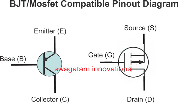
In this post I have explained the method of correctly replacing a BJT with a MOSFET, without affecting the final outcome of the circuit.
Introduction
Until MOSFETs arrived in the field of electronics, transistors or BJTs to be precise ruled the power switching circuits and applications.
Though even Bipolar Junction Transistors (BJTs) can not be ignored due to there immense flexibility and low cost, MOSFETs also have certainly become hugely popular as far as switching heavy loads is concerned and due to the high efficiency associated with these components.
However even though these two counterparts may look similar with their functions and style, these two components are completely different with their characteristics and configurations.
Difference Between BJT and MOSFET
The main difference between a BJT and a MOSFET is that, a BJT operation depends on current and needs to be proportionately increased with the load, whereas a mosfet depends on voltage.
But here the MOSFET gets an edge over a BJT, because voltage can be easily manipulated and achieved to the required degrees without much trouble, in contrast increasing current means greater power that's to be delivered, which results in bad efficiency, bulkier configurations etc.
Another big advantage of a MOSFET against the BJT is it's high input resistance, which makes it possible to be integrated with any logic IC directly, no matter how big the load may be that's being switched by the device. This advantage also allows us to connect many MOSFETs in parallel even with very low current inputs (in mA).
MOSFETs are basically of two types, viz. enhancement mode type and depletion mode type. Enhancement type is more frequently used and is the prevalent one.
The N-type MOSFETs can be turned ON or activated by applying a specified positive voltage at their gates while P-type MOSFETs will require just the opposite that is a negative voltage to get turn ON.
BJT Base Resistor vs MOSFET Gate Resistor
As explained above, a the base switching of a BJT is current dependent. Meaning its base current needs to be increased proportionately with increase in its collector load current.
This implies that the base resistor in a BJT plays an important role and must be correctly calculated to ensure that the load is optimally switched ON.
However, the base voltage for a BJT does not matter much, as it can be as low as 0.6 to 1 volts for a satisfactory switching of the connected load.
With MOSFETs it's just the opposite, you can switch them ON with any voltage between 3 V and 15 V, with current as low as 1 to 5 mA.
Hence, a base resistor may be crucial for a BJT but a resistor for the gate of the MOSFET may be immaterial. That said, a low value gate resistor must be included, just to safeguard the device from sudden voltage spikes and transients.
Since voltages above 5 V or up to 12 V are easily available from most digital and analogue ICs, a MOSFET gate can be quickly interfaced with any such signal source, irrespective of the load current.
How to Replace a Transistor (BJT) with a MOSFET
In general we can easily replace a BJT with a MOSFET, provided we take care of the relevant polarities.

For an NPN BJT, we may replace the BJT with a correctly specified MOSFET in the following manner:
- Remove the base resistor from the circuit because we don't typically need it anymore with a MOSFET.
- Connect the gate of the N-MOSFET directly to the activation voltage source.
- Keep the positive supply connected to one of the load terminals, and connect the other terminal of the load to the drain of the MOSFET.
- Lastly, connect the source of the MOSFET to ground.......DONE, you have replaced the BJT with a mosfet within minutes.
The procedure will remain as above even for a PNP BJT to be replaced with a P-channel MOSFET, you will need to just reverse the relevant supply polarities.
Compatible Pinout Replacement Diagram for PNP BJT with P-Channel MOSFET
