
Troubleshooting BJT circuits is basically a process of identifying the electrical faults in the network using multimeters across the various nodes in the circuit.
BJT troubleshooting techniques is a huge topic and therefore including 100 % solutions and strategies can be perhaps difficult within a single article.
Basically, the user should know about a handful of fundamental moves and measurements which may enable him to spotlight the location of the problem and help recognize the remedy.
Quite certainly, the initial step in having the ability to troubleshoot a BJT circuit would be to get thoroughly familiar with the tendencies of the network, and to have idea regarding the specified voltage and current ranges.
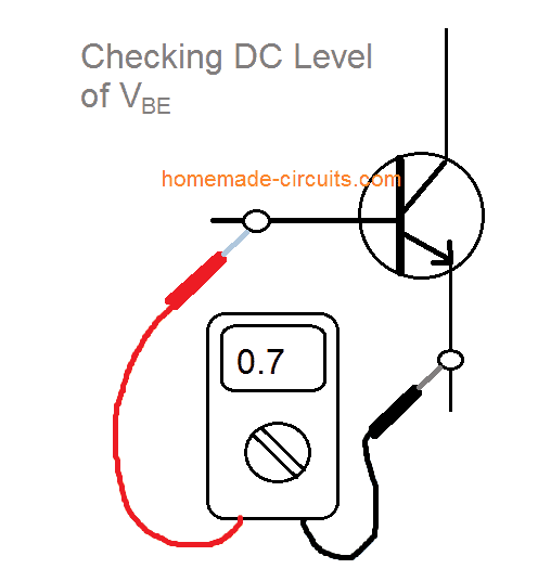
Checking Base-Emitter Voltage
Remember, for any BJT in the active region, the most crucial measurable dc level is actually its base-to-emitter voltage VBE .
For a BJT that's in a switched ON condition, the voltage across its base and emitter VBE should be in the vicinity of 0.7 V.
The correct relationships for testing VBE can be seen in below shown Figure. Observe that the positive (red) lead of the digital multimeter is touched to the base terminal for an npn transistor and the negative (black) lead to the emitter terminal.
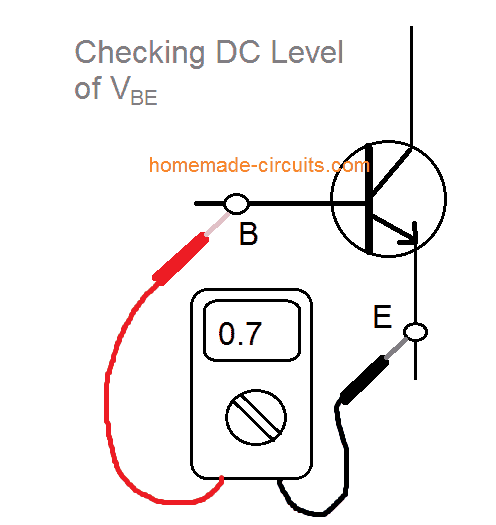
Any different form of display not matching the approximate 0.7 V, such as 0, 4, or 12 V, or a negative could be an indication of a faulty device, and the network connections might require a deeper analysis during such a situation.
For a pnp transistor, the very same strategy may be used however the meter probe polarity will need to be reversed for getting a similar response.
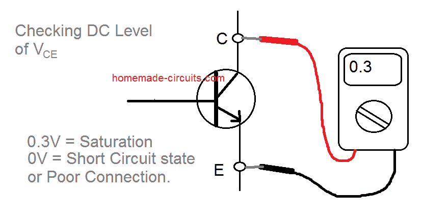
Checking Collector-Emitter Voltage
While troubleshooting a BJT, another voltage level having equal significance is the collector-to-emitter voltage.
Recollect from the general characteristics of a BJT that values of VCE in the vicinity of 0.3 V indicate that the device is saturated - a situation that must not really exist unless of course if the BJT is working in a switching mode. Having said that:
For a standard Bipolar Junction Transistor amplifier working in the active region, VCE is normally around 25% to 75% of VCC.
For Example if supply voltage VCC = 20 V, and a display on the meter for collector-emitter current VCE is may be 1 to 2 V or 18 to 20 V then undoubtedly it is an an abnormal outcome.
Unless, otherwise this is intentionally designed the network and connections must be inspected. This can be witnessed in the below shown image.
Checking BJT Open Loop Connections
If collector-emitter voltage VCE = 20 V (with supply VCC = 20 V) there could be a minimum of two chances that can arise, either the device (BJT) is damaged and has developed the characteristics of an open circuit across collector and emitter pins, or perhaps an interconnection between collector-emitter or base-emitter circuit loop is open.
The situation can be witnessed below, which may create a collector current IC being at 0 mA and VRC = 0 V.
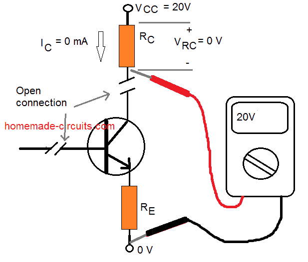
Here we can see the black probe of the voltmeter is attached to the common ground of the source and the red probe to the lower terminal of the resistor.
With collector current not present and a corresponding zero voltage drop around RC may result in a reading of 20 V.
When the meter is joined to the collector terminal of the BJT, the reading will probably be 0 V because the supply VCC is cut off from the active device due to the open circuit.
Checking Incorrect Resistance
Probably the most typical faults in the troubleshooting procedures is the incorporation of incorrect resistance values for any given network.
Think about the effect of utilizing a 680 Ohms resistor for the base resistor RB, instead of the required correct network value of 680 k.
For supply voltage VCC = 20 V and a fixed-bias configuration, the resulting base current would be 28.4 mA, instead of the required 28.4
μA. A huge difference!!
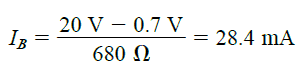
A base current of 28.4 mA would undoubtedly mean the device is in the saturation region which might result in damaging the device.
Due to the fact real resistor values in many cases are not the same as the minimal color-code value, it might be advisable to confirm the resistor value with a Ohm-meter before applying it in the circuit.
This will ensure that genuine values are closer to assumptive ranges and give the user certain assurance regarding the correct resistance value being exercised.
Troubleshooting Unknown Situations
There may be occasions when disappointment can build up.
You might have inspected the BJT on a curve tracer or some other BJT testing instrument and found it to be absolutely fine.
All resistor levels appear appropriate, the inter-connections look reliable, and proper supply voltage may have been employed - what then??
At this point the troubleshooter should make an effort to achieve a greater level of thinking.
Can it be that the internal network from the wire and the end connection of a lead is bad?
How frequently did you find that simply pressing a BJT at some appropriate places resulted in a “make and break” condition across connections?
In another circumstance you may find the supply switched on with the correct voltage but the current-limiting control has been mistakenly positioned at zero point, blocking the specified right amount of current to the circuit.
Naturally, the greater the sophistication of the network, the larger could be the spectrum of possibilities.
Whatever the case, probably the most successful strategies to troubleshooting a BJT network is always to examine the various voltage levels with reference to ground.
This usually is done by connecting the black (negative) probe of a voltmeter to ground and “touching” the essential points of the network with the red (positive) probe.
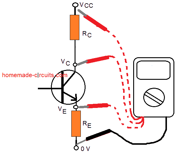
In the figure above, when the red probe is attached directly to supply VCC, it must display the fed VCC voltage level on the meter.
This is simply because the network works with a single common ground for the connected supply and other parameters.
At VC the reading must be less, depending on the voltage drop across RC. And the voltage VE must be lower than VC by a magnitude equal to VCE or the collector-emitter voltage.
The failure of registering any of these instances would be enough to define a faulty connection or element. If VRC and VRE carry fair values but VCE shows 0 V, the likelihood may be that the BJT is internally damaged resulting in a short-circuit kind of reading between collector and emitter terminals.
As noted earlier, if VCE registers a level of about 0.3 V as defined by VCE = VC - VE (due to the variation of the two quantities as assessed above), the system may indicate a saturated condition with a BJT that may be defective or perhaps may not be defective.
It must be relatively apparent through the above discussion that the voltmeter whether analogue or digital is pretty crucial in the repairing procedure.
Current (ampere) ranges are often determined through the voltage levels itself, measured across the various resistors, rather than unnecessarily “breaking” the network to insert the milliammeter probes of a multimeter.
For checking bigger schematics, precise voltage ranges are supplied in datasheets with reference to ground for effortless testing and recognition of probable troublesome areas.
Solving a Practical Example #1
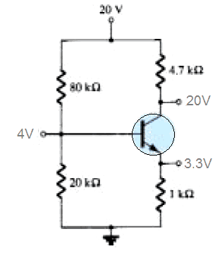
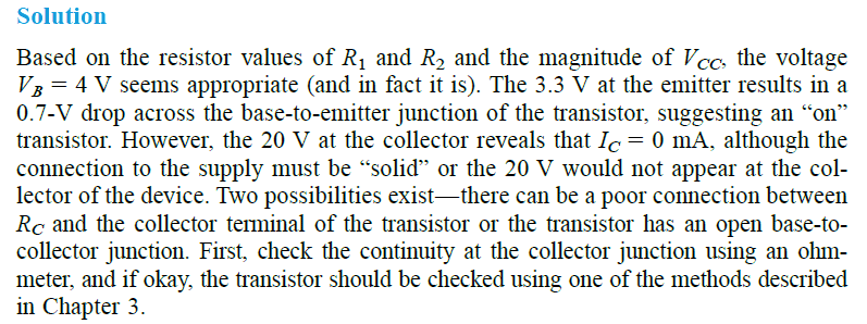
Referring to the various voltage readings for the following BJT configuration, find out if the design is supposed to work correctly, if not state the cause of it.
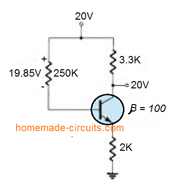
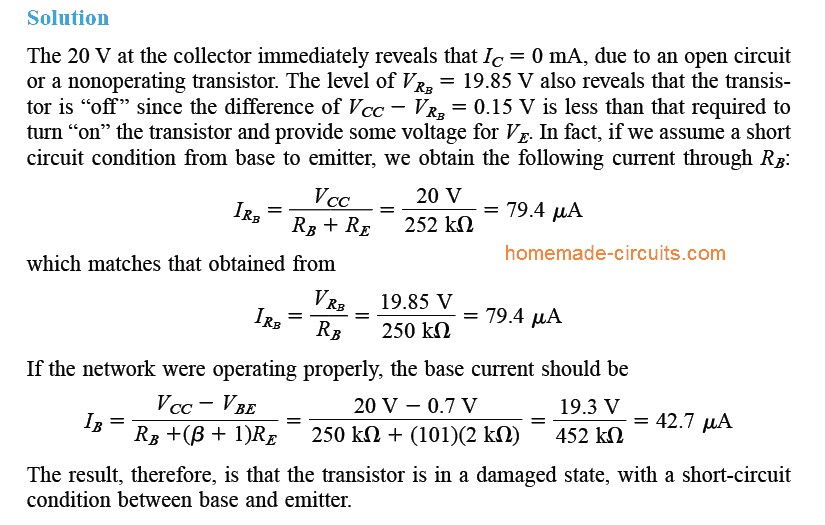
Example #2
Referring to the readings shown the diagram, determine whether the transistor is in “on” position or not, and if the network is operating properly.
Over to you
I hope the tutorial could enlighten you regrading how to troubleshoot BJT transistor circuits. The article discussed about an npn device so far.
I will soon try to update the post with more information regarding the troubleshooting techniques for a pnp transistor.
If you have further doubts please use the comment box below for expressing your thoughts.