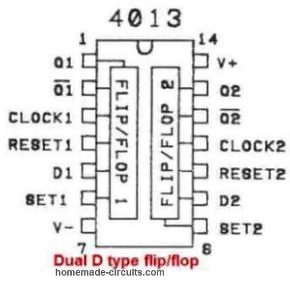
IC 4013 is a CMOS-based dual D-type flip-flop integrated circuit. It is widely used in digital circuits for applications such as counters, shift registers, and control circuits. Below is the detailed datasheet for IC 4013.
Pin Configuration:

IC 4013 has a total of 14 pins.
The pin configuration is as follows:
| Pin Name | Pin # | Type | Description |
|---|---|---|---|
| VDD | 14 | Power | This pin is the Supply Voltage (+3 to +15V) input of the IC |
| GND | 7 | Power | This pin is for supplying Ground (0V) input |
| Q1, Q2 | 1, 13 | Output | These pins generate the Output from the two D Flip-Flops |
| Q1, Q2 | 2, 12 | Output | These pins generate Inverted outputs from the two D Flip-Flops |
| CLK1, CLK2 | 3, 11 | Input | These pinouts are for supplying the Clock input for the two D Flip-Flops (Rising Edge) |
| D1, D2 | 5, 9 | Input | These pinouts are D (data) inputs for the two D Flip-Flops |
| S1, S2 | 6, 8 | Input | These pinouts can be used to Preset the Flip-Flop output to 1 |
| C1, C2 | 4, 10 | Input | These pinouts can be used to Reset the Flip-Flop output to 0 |
Electrical Characteristics:
- Supply Voltage: 3V to 18V
- Maximum Quiescent Current: 5µA at 15V
- Maximum Operating Current: 3mA at 15V
- Maximum Power Dissipation: 500mW
- Input Voltage High Level (VIH): 3.5V to 18V
- Input Voltage Low Level (VIL): 0V to 1.5V
- Output Voltage High Level (VOH): 90% of supply voltage
- Output Voltage Low Level (VOL): 10% of supply voltage
- Operating Temperature Range: -55°C to +125°C
Functional Description:
A circuit that can store one bit of data is called a D flip-flop. It may either provide HIGH or LOW output.
As the clock switches from LOW to HIGH, the output adapts to whatever is on the data (D) input. Also referred to on the rising edge of the clock. (Some D flip-flops, on the other hand, alter on the falling edge.)
The D flip-flop only analyzes what is on the data (D) input at the precise instant when this transition occurs, according to this.
Certain D flip-flops only alter their output when the clock swings from HIGH to LOW because they have an inverted clock input. On the falling edge is the term used to describe this.
Furthermore, the CD4013's D flip-flops feature Set (S) and Clear (C) pins. Irrespective of the clock, these can be utilized to either reset the output to LOW or set it to HIGH.
Application:
IC 4013 is commonly used in digital circuits for various applications such as:
- Counters
- Shift registers
- Control circuits
- Frequency dividers
- Timers
- Flip-flop circuits
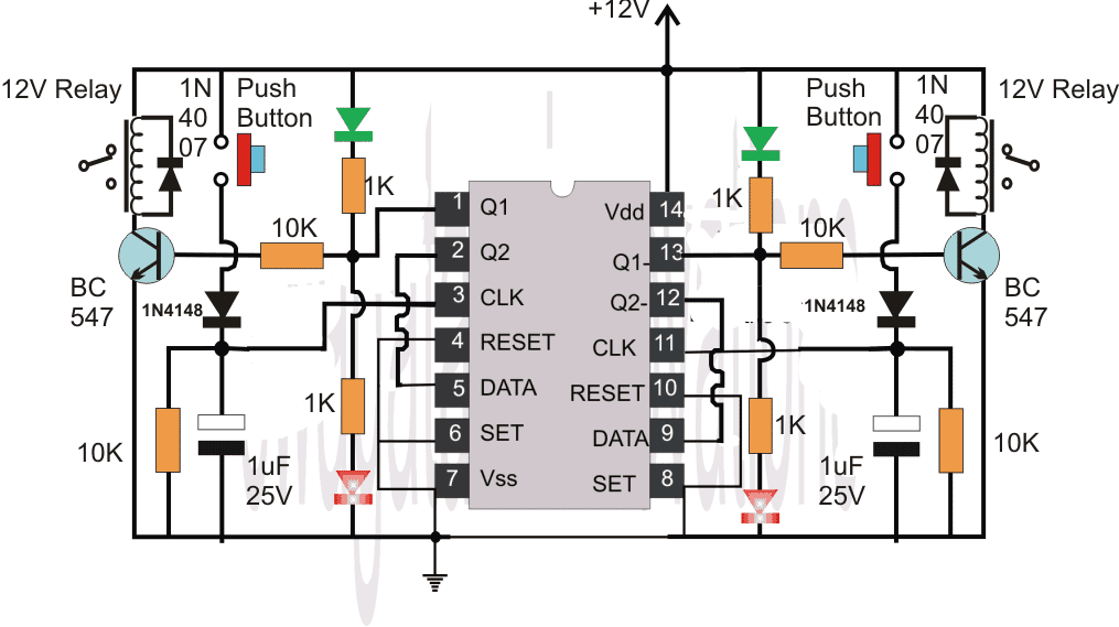
An example circuit of the IC 4013 can be seen in the following figure:

The relay on both side of the IC 4013 can be switched ON/OFF by pressing the associated push button.
More explanation can be found in this flip flop article
In conclusion, IC 4013 is a versatile and often used in digital circuits because of its low power consumption, strong noise immunity, and simplicity of usage.