
The IC CD4020 is a 14-bit Binary Counter IC, manufactured by Texas Instruments. It consists of 12 output pins numbered Q1 to Q14, except Q2 and Q3. Whenever an Input clock pulse is applied to the clock pin of the IC, the binary value is increased from 00 0000 0000 0000 to 11 1111 1111 1111. This corresponds to 0 to 16383 in decimal.
This IC functionality may be utilized to produce counters and dividers, and it's additionally widely employed in timing-related applications. Thus, if you're seeking for a 14-bit binary counter that can be incremented with a clock pulse, this IC could be the one you are looking for.
Electrical Characteristics:
The electrical characteristics of IC 4020 are as follows:
- Supply Voltage (VCC): 3V to 15V
- Operating Temperature Range: -55°C to +125°C
- Input Voltage (VIH): 2/3 VCC to VCC
- Input Voltage (VIL): 0V to 1/3 VCC
- Output Voltage (VOH): VCC - 0.1V
- Output Voltage (VOL): 0.1V
Pinout Configuration
The pinout configuration of the IC 4020 can be seen in the following diagram:
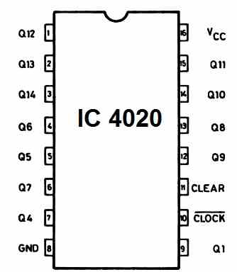
The IC 4020 has in all 16 pinouts.
Pin#16 is the positive supply input of the IC
Pin#8 is the ground supply or 0V pin of the IC.
Pin#10 is the Clock input pinout of the IC. This pin receives the clock frequency input
Pin#11 is the Clear or the reset pinout of the IC. This pinout can be applied with a positive high to clear the outputs to zero.
The remaining pinouts, pin#9, 7, 5, 4, 6, 13, 12, 14, 15, 1, 2, 3 are all outputs of the IC 4020.
Understanding the pinout function of IC 4020
The pinout working of the IC 4020 can be understood with the following points:
Q1 means, divide 2 to the power 1 = 21
Q4 means, divide 2 to the power 4 = 24
In this way, Q12 means, divide 2 to the power 12 = 212
Now, which frequency will be divided by the above explained pinouts? It is the input frequency at pin#10 of the IC, which is the clock frequency.
The clock frequency applied at pin#10 will be divided the respective output pins Q1, Q4, Q5, Q6, Q7, Q8, Q9, Q10, Q11, Q12, Q13, Q14.
For example, let's consider pin#4 which is Q6. Q6 = Divide by 26 which is equal to 64.
This implies that if the frequency at pin#10 of the IC is 64 Hz, then the pin#4 which is Q6 will generate a frequency of 1 Hz.
We get the result by dividing the 64 Hz frequency at pin#10 by Q4 output, which is equal to 26 = 64, that is 64/64 = 1 Hz. Therefore, Q4 will generate a 1 Hz frequency when 64 Hz frequency is applied at pin#10.
Applications
The main applications of the IC 4020 is as given below:
- Frequency division
- Timing delays
- Binary counting
- Clock generation
- Pulse generation
- Data counting.