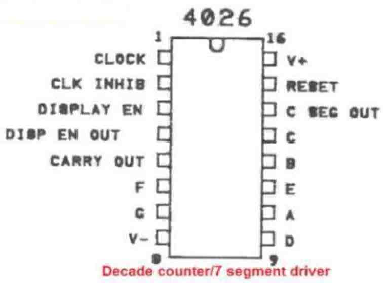
IC 4026 is comprised of a 5-stage Johnson decade counter and an output decoder that transforms the Johnson code into a 7-segment decoded output to drive a single 7 segment numerical display. These devices offer significant advantages in display applications that prioritize low power dissipation and/or low package count.
Both sides of IC 4026 have common inputs, including CLOCK, RESET, and CLOCK INHIBIT, while common outputs include CARRY OUT and the seven decoded outputs (a, b, c, d, e, f, g). CD4026 also features additional inputs and outputs, such as the DISPLAY ENABLE input and DISPLAY ENABLE and UNGATED "C-SEGMENT" outputs.
When a high RESET signal is applied, the decade counter is reset to its zero count. The counter advances one count on the positive transition of the clock signal, provided the CLOCK INHIBIT signal is low. Counter advancement through the clock line is blocked when the CLOCK INHIBIT signal is high.
The CLOCK INHIBIT signal can function as a negative-edge clock when the clock line is held high. The JOHNSON counter has antilock gating, which ensures proper counting sequence.
The CARRY-OUT (Cout) signal completes one cycle every ten CLOCK INPUT cycles, and it is utilized to clock the next decade directly in a multi-decade counting chain.
The seven decoded outputs (a, b, c, d, e, f, g) activate the appropriate segments in a seven-segment display device used to represent decimal numbers 0 to 9. The CD4026 outputs are only activated when the DISPLAY ENABLE IN is high.
The IC 4026 series type is available in 16-lead dual-in-line plastic packages (E suffix), 16-lead small-outline packages (NSR suffix), and 16-lead thin shrink small-outline packages (PW and PWR suffixes).
Pinout Configuration

- Pin 1: This is the Clock input pin, where an external clock signal should be applied.
- Pin 2: This is the Clock inhibit pin. Connecting this pin to +Vcc, causes the IC to reject the clock input. When connected to GND, this causes the IC to accepts input clock pulses.
- Pin 3: This is the Display enable / disable pin. When connected to +Vcc, it enables the 7 segment pins (A to G) so that they become active. When connected to GND it disables all the display pins.
- Pin 5: This pin works in the divide by 10 mode or carry-out. This pin is turned high for every 10th input pulse. This pinout becomes useful when number of IC 4026 are cascaded to operate so that 2 or more digits can be used at the output.
- Pins 6, 7, 9, 10, 11, 12,13: All these pinouts are the output pins for common cathode 7 segment display (A to G).
- Pins 16 and 8 are +Vcc and GND respectively.
- Pin 15: This pinout is the Reset pin. When this pin is connected to the supply positive the counting process is reset to zero. To enable normal counting operation of the IC this pin must be grounded.
Absolute Maximum Ratings:
- Supply Voltage (Vdd): 18V
- Input Voltage (All inputs): -0.5V to Vdd + 0.5V
- Output Voltage (All outputs): -0.5V to Vdd + 0.5V
- Operating Temperature Range: -55°C to 125°C
- Storage Temperature Range: -65°C to 150°C
Electrical Characteristics:
- Supply Voltage Range: 3V to 15V
- Supply Current (Quiescent): 5uA typical, 10uA max.
- Supply Current (Active): 3.5mA typical, 10mA max.
- Clock Frequency Range: DC to 5MHz
- Output Voltage (High): 90% of Vdd min.
- Output Voltage (Low): 10% of Vdd max.
- Propagation Delay Time: 70ns typical, 100ns max.
Applications:
- Digital counters
- 7-segment display drivers
- Timers and clocks
- Frequency dividers
- Decade counters
Two practical application circuits can be learned in the following links:
Visitor Counter Circuit Using IC 555 and IC 4026
Vehicle Parking Lot Counter Circuit
Digital Counter Circuit using IC 4026
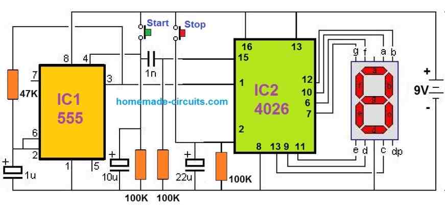
The following diagram explains how to build a simple digital frequency counter using the IC 4026.
