IC 4046 is a Phase-Locked Loop (PLL) chip that consists of various functional blocks such as a voltage-controlled oscillator (VCO), phase detector (PD), phase comparator (PC), charge pump (CP), and other circuitry.
Here is the datasheet for IC 4046:
General Information:
- Manufacturer: Multiple Manufacturers
- Product Category: Phase Locked Loops (PLL)
- RoHS: Yes
- Product: CMOS Micropower Phase-Locked Loop
Electrical Characteristics:
- Supply Voltage (Vcc): 3V to 18V
- Input Voltage (Vin): 0V to Vcc
- Operating Temperature: -55°C to +125°C
- Output Current (Iout): 20 mA
- Frequency Range: 0.01 Hz to 10 MHz
Features:
- Wide supply voltage range
- Low power consumption
- High stability and accuracy
- Excellent temperature stability
- Low external component count
- Output compatible with TTL, CMOS, and ECL logic families
Pin Configuration:
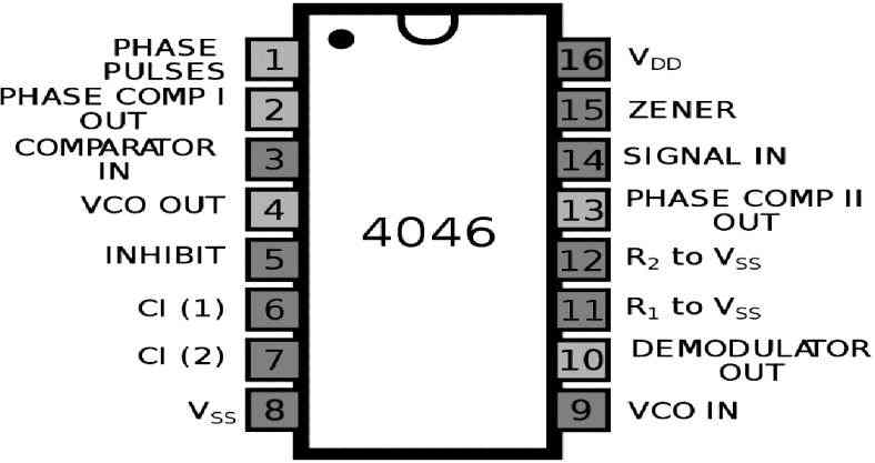
The pinout configuration of the IC 4046 can be understood by looking at the following diagram and the below given explanation:

Pin#1 = PCP_OUT (phase comparator pulse output)
Pin#2 = PC1_OUT (phase comparator 1 output)
Pin#3 = COMP_IN (comparator input)
Pin#4 = VCO_OUT (VCO output)
Pin#5 = INH (inhibit input)
Pin#6 = C1A (capacitor C1 connection A)
Pin#7 = C1B (capacitor C1 connection B)
Pin#8 = VSS (ground supply voltage)
Pin#9 = VCO_IN (VCO input)
Pin#10 = SF_OUT (source-follower output)
Pin#11 = R1 (resistor R1 connection)
Pin#12 = R2 (resistor R2 connection)
Pin#13 = PC2_OUT (phase comparator 2 output)
Pin#14 = SIG_IN (signal input)
Pin#15 = ZENER (Zener diode input for regulated supply)
Pin#16 = VDD (+supply voltage)
How the IC 4046 Works

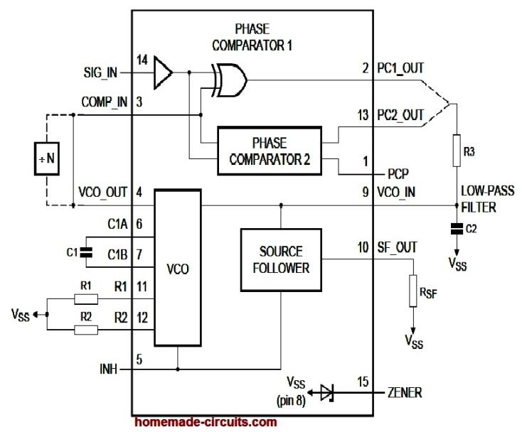
Referring to the internal diagram of the IC and the pinouts we can understand the basic working of the IC 4046 through the following explanation.
The phase detector detects the phase input. The detected output is fed to a VCO which is a voltage controlled oscillator. This creates a feedback loop across the phase detector output and VCO.
The feedback from the phase detector output causes the VCO to adjust the input phase and frequency, so that the output is phase locked and the output phase is always perfectly synchronized with the input phase.
There are a couple of phase comparator in the IC, I will try to explain one of these phase comparators.
There is also a VCO or voltage controlled oscillator inside the IC 4046. he VCO has an externally connected capacitor and resistors, which sets the center frequency for the VCO output. This sets up the VCO oscillator.
The VCO has an input voltage pinout VCO_IN which is pin#9.
If suppose we put a potentiometer across the Vcc and ground pins of the IC, and connect the wiper of the pot to the above pin#9 then we can change the VCO output frequency proportionately by changing the potentiometer adjustments.
So basically, by adjusting the voltage at the input of the VCO pin#9, we can adjust the VCO output frequency at pin#4.
Now, I have explained how the phase detector or the phase comparators work.
The phase comparators are built using exclusive OR gates. There are two inputs to the phase comparators, namely: SIG_IN, COMP_IN.
The exclusive OR gates checks and analyzes the above two input signal waveforms and averages out the ON/OFF times of the two frequencies and creates a mean waveform across their outputs. These outputs are PC_1 out, and PC_2 out respectively.
Now, how do we generate an average potential resulting from the above two output waveform of the IC 4046?
We do this simply by adding a low pass filter across the two outputs of the comparator and the gorund.
This low pass filter is created by adding a resistor R3 and capacitor C2 between the two outputs of the comparator and ground line.
This low pass filter will analyze the corrected ON time and OFF time across PC_1 and PC_2 and will convert them into an average constant DC at the center of the RC network.
This average RC potential acquired from the outputs of the phase comparators can be fed back to the VCO so that it automatically adjusts the input signal phases according to the output phase.
There are a couple of more items included in the IC 4046 which are optional but can be sometime very useful indeed.
These are a zener diode and a MOSFET source follower.
The source follower is connected with the average DC from the RC network and this buffered by the source follower so that this potential can be used for driving an external load such as a motor or an LED.
The zener diode can be used for stabilizing an external voltage to the zener value.
Application:
- Frequency synthesizers
- Clock recovery circuits
- FM demodulators
- Phase-locked loops
- Modulators and demodulators
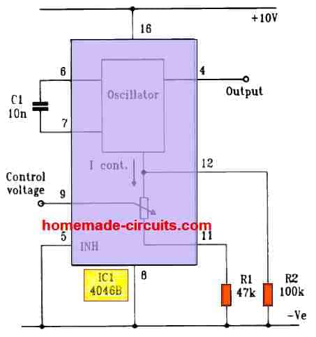
One practical application of a voltage controlled oscillator circuit using the IC 4046 can be seen in the following diagram:
