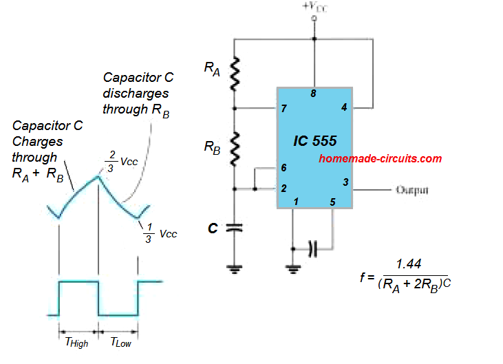
This IC 555 software calculates the values of the resistors and capacitors for a NE555 timer chip, which is designed as a astable multivibrator (oscillator), or square wave generator. You simply have to type in the duty cycle and the frequency and the calculator will work out realistic values for the resistors and capacitors.
Alternatively, you can insert the RA, RB and C values manually to check what corresponding output results you get for the frequency and the Duty cycle, and then you can change the figures accordingly until the intended results are determined.
Please remember that the lowest duty cycle will be 50 %, therefore should you need a smaller duty cycle you will need to apply an inverter on the output, by ticking the check box.
Furthermore the parameters explained in the equations of the IC 555 astable timer are only estimations which can be inaccurate by approximately 20% from the empirical outcomes.
NE555 Astable Circuit Schematic with Calculations

IC 555 Astable Calculator
In a 555 astable circuit, R1 is connected between pin 7 (discharge) and VCC, while R2 is between pin 7 and pin 6. The capacitor (C) is connected between pin 6 and ground.
Results:
Frequency: 0 Hz
Duty Cycle: 0 %
ON Time: 0 ms
OFF Time: 0 ms