In this article I have explained a simple circuit for enabling the turn signal lamp of any car to carry out a two-way function of DRL lights as well as well the stipulated turn lights. The idea was requested by Mr. Artem.
Technical Specifications
Thank you for your fanaticism with electronics, this is really noticeable through your blog. I've been experimenting with some of your circuits, and everything is okay for now.
Here I kindly ask your professional advise on my project.
Some tiny vehicles have a certain lack of room to place LED lights in order to look fine. For one of those, Nissan Micra i was asked to combine LED Turns and DRL lights without placing one next to another..
Considering a small city car ergonomics i searched the market.
I ordered twin color Y+W 1Watt 350mA LED-Emitters from China, so I could combine both functions by means of some kind a controller at one spot.
And as it often happens, seller did not provide any specs for his product.
4-pin LEDs actually have common "+" so i can not drive six of them in series or implement any known driver. Please advise something useful, I believe you are able to.
Thanks in advance,
Artem,
Moscow,
Russia.

The Design
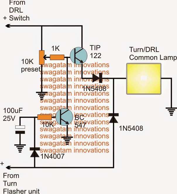
The proposed circuit which combines and enables illuminating DRL and turn signal lamps through a single common lamp can be seen above.
The circuit basically allows the same lamp (preferably LEDs) to implement a dual function of DRL lights as well as turn signals, depending on which one is switched ON.
The DRL switch is supposed to be switched ON permanently, so that the connected lamp illuminates through the TIP122 transistor, and as soon as the turn signal flasher is switched ON, the TIP122 is instantly disabled through the BC547, allowing the turn signal to flash the LED at the given frequency.
The above happens since the BC547 becomes triggered ON through the turn signal switching and keeps the TIP122 base grounded and disabled.
The 100uF/25 plays a crucial role here, and makes sure that the BC547 stays disabled for both the ON and the OFF periods of the turn signal inputs, therefore this capacitor might require some tweaking until the right minimum timing is determined.
Bigger values will work but this might result in a delayed switch ON of the DRL each time the turn signal is deactivated, therefore the 100uF value could need some adjustments.
The 10k preset at the base of the TIP122 may be used for determining the brightness level on the DRL, so this becomes an added feature in the design.
Feedback from Mr. Artem
Thank you for the circuit.
But it seems you get me a little wrong. I wanted the circuit to drive 350ma double color leds, which has single common "+"positive and two "-"negative pins for white and yellow respectively. Both lamps are in single body for ergonomic reasons.
Your suggested circuit doing the job well but we must take two colors with common positive pin in account.
Solving the Circuit Query
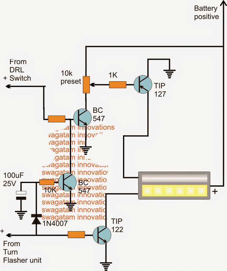
As per the above response, the earlier diagram can be modified as shown below for executing the new function.
I have assumed the LEDs to be having the current limiting feature originally, therefore it's not been shown here or included in the proposed designs. Otherwise 5 ohm, 2 watt resistors could be included in series with the respective negative lines of the LED module.

Question Regarding Switchback Driver Controller
The following request was sent by Mr. Dejan Djordjevic
Hi Swagatam,
Can you build a solid state switchback driver controller. You probably know has this works but if needed I have explained.On internet I find some schematics but they use relay and whole assembly is to big. Can you make schematic without relay?
This controller have 3 wires, yellow, black and red.On yellow wire you connect signal from car turn signal, on red connect DRL (daytime runing lights) and black is ground for both.When DRL is ON and you turn ON turning signal DRL will go OFF.When turn signal is switched OFF DRL will automaticaly go ON again.So, this controller is just switching between DRLs and turn signals.You can see one example here
My Reply:
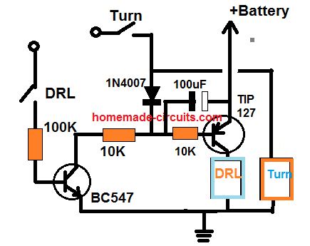
Please check the following diagram, I hope this will do the job

Feedback from Dejan
I tried this circuit and it's working fine.Just small correction if it is possible- can you add a little delay when switching from turn signal to DRL?For example-if turn light is not working for 2 seconds then DRL is switching on.
My Reply:
The delay feature is already present. You can increase the 100uF capacitor value, or increase the 10K near the transistor base to increase delay