In this post I have explained all the basics of inductors, its working principle, and how to design inductors with the help of formulas and calculations.
Inductors are vastly used from mobile, laptop chargers to high-end communication equipment like mobile base stations to the satellites orbiting the earth. Let us take a deep dive into the world of inductors.
What is an Inductor?
An inductor is a two-pin passive component that stores energy in the form of a magnetic field when a current flows through it.
It could be a tiny piece of straight copper wire or wire wound into rings called a coil.
An inductor inherently opposes the change of current through it. It is denoted by the letter L and its SI unit is Henry, H.
Figure 1 depicts the symbol of an inductor.

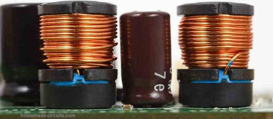
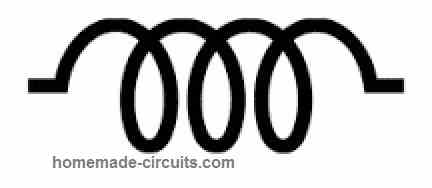
Figure 1: Symbol of Inductor
Working of Inductor
Let us take a simple circuit as shown in Figure 2, where a battery is connected to an inductor L in parallel, and a switch S in series. When the switch S is turned on, current starts flowing through the inductor, a magnetic field is produced and the inductor becomes an electromagnet.
This electromagnet has its North Pole, N, and South Pole, S, like a conventional magnet. And magnetic lines flow from N to S pole.
Now, if we reverse the polarity of the battery, the direction of the current changes, consequently poles of the electromagnet are reversed, and the direction of magnetic lines of force also gets reversed.
The strength of this induced magnetic field is measured in magnetic flux density denoted by the letter B and the SI unit is wb/m2. Where magnetic flux ø is the total number of magnetic lines and measured in SI unit Weber.
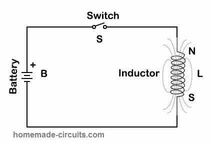
Figure 2: Inductor Circuit
EMF
Now let us continuously turn on and off the switch S, this is similar to applying alternating current. Any change in the electric current induced, changes the flux. This change in flux, induces an electromotive force (EMF) in the inductor which is given by :
ε= -Ldl/dt
Where ε is the electromotive force in volt, L is the inductor value in Henry and dl/dt is the rate of change of current with respect to time.
Kindly note that, the negative sign which indicates the EMF is of opposite polarity to the applied voltage. This is called back EMF or counter EMF.
Inductive Reactance
The opposition, resistance, to the induced current, induced by the magnetic field is called Inductive reactance and given by :
XL= 2πfL
Where XL is inductive reactance in ohms, f is the frequency in Hz, and L is inductance in Henry.
How much is one Henry?
An inductor has an inductance (L) of 1 Henry if the EMF (ε) induced in it is 1 Volt when the current is changing at the rate of one ampere per second (dI/dt).
Inductors in Series and Parallel
Like other discrete components resistor and capacitor, we can connect Inductors in series and parallel too.
In series, see Figure 3, total equivalent Inductance will be :
L total =L1+L2+….Ln
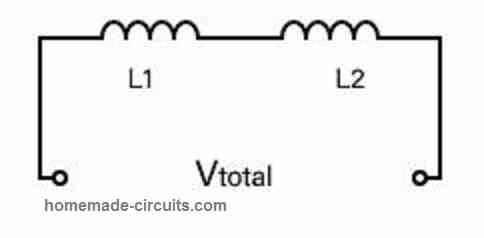
Figure 3: Inductors in Series
In parallel, see Figure 4, total equivalent, Inductance will be:
Ltotal = 1 / (1/L1+1/L2+…1/Ln)
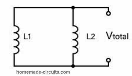
Figure 4: Inductors in parallel
Q Factor of the Inductor
There is no such thing as an ideal inductor in the practical world so every inductor has some resistance, R, in addition to inductance. The lower the resistance higher the Q or quality factor of the coil.
Q Factor is expressed as:
Q = wL / R = XL / R
Thus, Q is the ratio of inductive reactance of the inductor and its resistance. As we can see Q is inversely proportional to the R so the lesser the resistance of the inductor better the Q factor it has. This is also called the efficiency of the coil or inductor.
Types of Inductors
There are different types of inductors available based on their geometrical shape and type of core used.
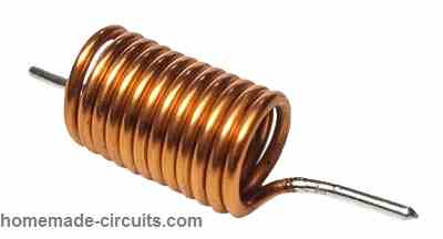
Air Core
As the name suggests, these have only air in the core of their winding. Air does not provide the flow of magnetic lines freely, rather opposes the flow of the line. This is called reluctance R (in H-1).
As air has high reluctance these types of inductors are used in high-frequency RF circuits where a low value of inductance is required.
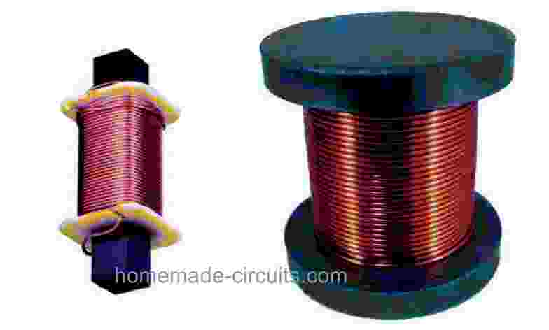
Iron Core
In this type of inductor, wire is wound on a ferromagnetic material soft iron as its core. Iron core allows an easy path to the magnetic lines of force.
This property is called permittivity µ (in H/m). As iron core inductors have a higher value of inductance they are used in low-frequency line filtering and audio equipment.
Ferrite Core
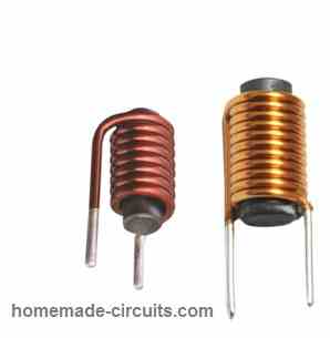
These types of inductors are most widely used. In this type of inductor, ferrite is used as a core. They find their application mainly in power conversion, broadband communication, and interference suppression.
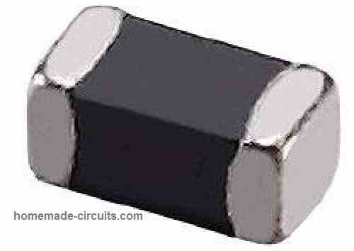
Multi-Layer Inductors
In this type of inductor, layers of coils are wound one over the other. They are used in communication equipment like mobile and Bluetooth devices. These types of inductors have a high inductance level.
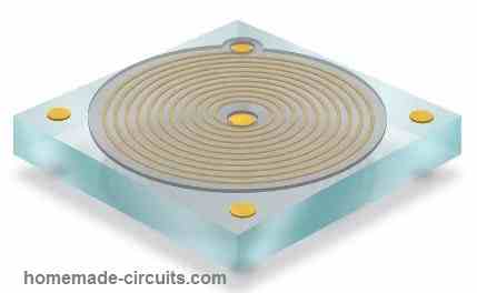
Thin-film Inductors
These types of inductors are made with thin-film coils, shaped like spirals. They are designed similar to semiconductors. They are made up of alumina, ferrite, or magnetic material. They are also called chip inductors. They find applications in wireless LAN networks, voltage-controlled oscillators, and impedance matching.
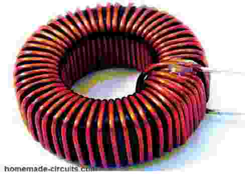
Toroidal Inductor
They have a geometrical shape like a donut made with a ferromagnetic core on which coil is wound. They are widely used in power supplies, inverters, and amplifiers.
Designing an Inductor
Here I have explained to design a ferrite core inductor. There are formulas available on the internet for designing ferrite core inductors based on their geometrical shape. But for that, one has to make precise measurements like outer diameter, inner diameter, spacing, wire thickness, which would require instruments like Screw Gauge and Vernier Calliper as an overhead, and involve manual error also.
I don’t want to intimidate you, however you may find different versions of formulas that are available for the same shape of inductor design, that could utterly confuse you.
The methodology presented here is very easy to use and reliable also.
Before I begin let me introduce you to a new parameter AL called inductance factor or inductance per turn or permeance.
It is a value of specific inductance (measured with 1 turn) characteristic for a given magnetic core, measured in Henry/turn2.
And it is given by:
AL=L / N2
For designing an inductor, following two parameters must be known:
- Inductance required, L (in millhenries)
- DC Current, I (in ampere)
Now compute L*I2 for a required inductance of 100 µHenries when the maximum current is 1A
So , L*I2 = 100 x 10-6 x 1 = 0.1 millijoules
Next, read the corresponding AL value for LI2 by looking at the ferrite core selection chart, depending on which geometrical shape of core you have selected.
We have chosen a PQ-type ferrite core, see figure 5, for our design so we will look at AL vs LI2 in the PQ chart, see figure 6.
This chart data will be supplied by the ferrite vendor or you can search online if you know the exact specifications and part number of the ferrite. Seeing the chart for PQ type core, , 42016 (part number) we have AL=1200.
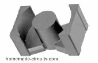
Figure 5: PQ Type Core
Now we have the following data with us:
- Inductance required = 0.1 milliheneries
- current = 1 Ampere
- AL = 1200
As we know current is 1A, and looking up the wire sizing table, select SWG22 copper wire size which can carry current up to 1.2A.
Calculate the required number of turns by putting these values in the below equation:
N= 103√L/AL
Calculations:
N= 1030.11200
N = 1000*0.3162/34.6410
N = 9 Turns
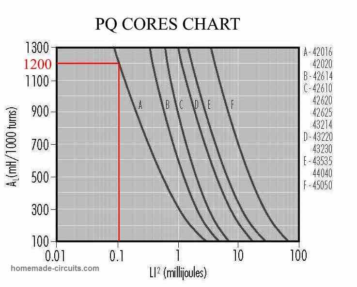
Figure 6 : PQ Ferrite Core Chart
More Inductor Calculations
All inductive components used for tuning, filtering, coupling, choking, and interference suppression are covered in this chapter. Manufacturers differ greatly in the variety of inductors they provide, more than for most other sorts of materials.
Some retailers only have a few recognized varieties, while others have hundreds. If you can't locate what you're looking for in one company's catalog, you must try another.
Inductors come in a variety of shapes and sizes.
Chokes are intended to filter out unwanted signals or inhibit them. These are constructed on ferrite cores with a high loss. Audio-frequency chokes with large inductance (>1H) and radio-frequency chokes with low inductance (0.22/uH to 1mH) are the two types. Multiple chokes are the types that are pre-connected and ready to use as filters.
Tuning coils are designed for radio frequencies larger than 100 kHz. These are wrapped on a plastic former and have a threaded ferrite or iron dust core that could be trimmed with a screwdriver. These coils need to be mechanically strong so that shock or extreme heat do not push them out of alignment.
Saturation of the core isn't a big concern because they can only conduct tiny currents. Inductors with two or more layers wound on the same former, such as those used in oscillators and high-frequency transformers in radio and television circuits, fall into this group.
Inductors that can store energy are intended for use in power supplies. Stability is unimportant, however these must be able to achieve a high saturation flux density.
The core frequently contains a gap to improve saturation, or is constructed of iron dust, that include air spaces within the core. Such coils wound on ferrite torroids, for example, are designed to carry large currents.
Choosing Ready made Inductors
While choosing a coil, the following factors must be considered:
Self-inductance (L): This could range between 1/uH and 1.5H.
Quality factor (Q): This is a magnitude that indicates the inductor's selectivity – the strength of its response to signals at a certain test frequency. The better the coil, the higher the value of Q. Numbers usually vary from 20 to 100.
Q increases with frequency and increases with inductance in coils. A coil built on a pot core is often advised for attaining optimum Q at relatively lower (i.e. audio) frequencies.
Maximum rated current: Crossing this current limit could result in coil melting.
Temperature coefficient: This is rarely mentioned, although it is typically 100 — 200 ppm/°C, however it can be higher.
Screening: A metal can protects the coil from external magnetic fields while also preventing the coil's magnetic field from interfering with other sections of the circuit.
Other characteristics, such as adjustable frequency range, stability, and DC resistance, are frequently listed in catalogs if they are relevant to the designer.
How to Calculate Inductors
Despite the availability of a wide range of inductors, some specific coils might be required to match a particular application. Plastic formers, iron dust cores, pot cores, ferrite rods, torroids, and enameled copper wire in different sizes can be acquired for winding inductors as per the requirements.
1) Air-cored single-layer coil: The coil's length ℓ is ten or more times bigger than its radius r. The needed number of turns can be calculated using the following formula:
N = 5/r x √L(10ℓ + 9r)
In this formula r and C are in mm and L is in uH.
Example#1: The number of turns necessary to wind a coil having a length of 40 mm, radius 4 mm, and self-inductance 10 uH is = 5/4 x √10(10 x 40 + 9 x 4)
= 1.25 x √(10 x 346)
= 1.25 x √4360 = 82.5 turns
For the coil, use enameled copper wire. Smaller coil d.c. resistance and the greater Q could be achieved by using the thicker coil wire.
How to Use ferrite pot core:
The inductance factor or specific inductance of the core, AL, which is the inductance per turn squared, is typically provided by the manufacturers. This simplifies the computations, as the number of turns necessary could be figured out using the following formula:
N = √(L/AL)
Example:
Let's say we have a coil with an AL = 250mH/turn2 . Then in order to wind a 150 mH coil, we can calculate the number of turns as given below:
N = √(L/AL)
N = √(150 x 10-3) / (250 x 10-9) = √60000 = 775 turns
It is important to note that if the wire is excessively thick, it may be impossible to accommodate the complete number of winding on the bobbin. The magnetic field is almost totally restricted inside the core with a pot core, therefore screening is typically unnecessary.
How to Use Torroids
Torroids are a quick and easy approach to make high-frequency chokes and transformers to a specific value. Because the magnetic field is restricted to the core, screening is not required.
Torroids are constructed from a variety of blends, each with its own unique permeability and tailored to a certain spectrum of resonant frequencies. Manufacturer's data tables include torroids of various sizes and blends, as well as the inductance, which is frequently of a 100-turn coil.
The number of turns necessary for coils with different inductance values could be estimated in the same way as explained just above. We also get tables that also specify which wire gauge required for the winding.
Using Ferrite Beads
These types of ferrite cores may be fitted onto the wires to serve as high-frequency chokes. They are very effective in suppressing transients on power supply cables.
The 555 timer IC for example, generates significant spikes that might impact other parts in the very same circuit. These spikes could be muffled by passing the power lines to the ic via one or two ferrite beads.
please can I make inductor with laminations sheets efficiently, what will be the efficiency compared with ferrite inductor
Yes that’s possible, efficiency may be good and same as a ferrite core, at frequencies below 100Hz
Thanks for your educational information. I read one of notes that multiple of tiny guage wire is better than single large guage wire windings for inductor, why is it better. Most inductors with large size wire.
Yes, that’s called bifilar winding, and it helps improved absorption and delivery of current. It minimizes skin effect.
Hi Mr. Swagatam;
I have a couple of transmitter and receiver (p/n: fs1000a and xy-mk-5v 433Mhz). Sould I
connect them any aircore inductors as an antenna or no necessary?
Hi Suat, An inductor is not necessary for the antenna, the antenna can be any long flexible wire. However, I have seen the antenna wire is intentionally coiled which itself works like an antenna, but I don’t find any difference in performance.