
A simple, cheap yet highly effective infrared remote control safe lock circuit can be studied in the following post.
Using IC LM567
The LM567 IC is one of my favorites simply because it's too versatile, and becomes applicable in most of the crucial circuit concepts through hassle free configurations.
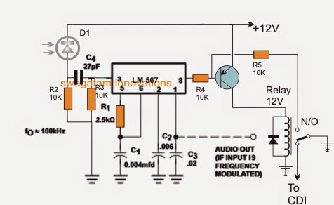
One such crucial yet simple IR remote control receiver application can be seen in the above diagram, which activates only through a unique predetermined frequency as set by R1/C1 in the circuit.
The above concept can be used in automotive security applications for locking the safe/vault through a uniquely set frequency code.
In the shown circuit R1/C1 determines the latching frequency of the unit, which may be calculated using the following formula:
f = 1/R1C1, which constitutes to be 100kHz for the shown values of R1, C1.
Pin3 which is the receptor pinout of the IC is configured with a IR diode for receiving an incoming tone locked frequency set at the matching 100kHz frequency.
How it Works
When such a matching frequency is detected at pin3 of the IC, pin8 responds and becomes low momentarily activating the transistor latch.
The transistor and relay latch together to acknowledge the response and open the safe lock for the user.
Any other frequency which may not coincide with the set R1/C1 value is simply rejected by the IC keeping the vault secured and locked, thus the system becomes extremely foolproof and safe from potential bike thieves.
pin1 output from the IC can be configured with an audio amplifier and buzzer in case an audio signal is felt essential during the remote control activation.
However this may require the transmitter to be equipped with a modulated audio signal over the carrier base frequency.
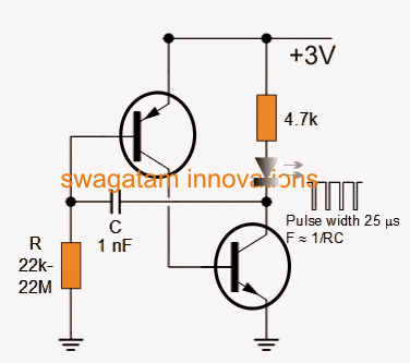
A very simple complementing IR remote handset circuit may be seen below:
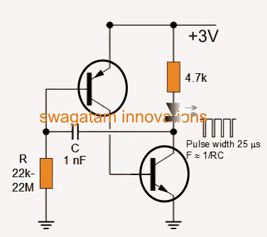
It's a simple two transistor R/C based oscillator, whose frequency is determined by the shown R and C values and coincidentally here too the formula is identical to its Rx counterpart, that is:
f = 1/RC
Thus the Tx circuit frequency becomes much easier to calculate and match with the LM567 receiver circuit discussed in the previous section.
For activating the Rx circuit, the above Tx circuit IR diode emission simply needs to be focused on the IR receiver diode of the Rx unit. This instantly unlocks the Rx circuit for the intended results.
The infrared remote control security lock circuit can be used for locking a multitude of other security devices which require a foolproof uniquely coded locking operations.