
In this article I have explained about a simple infrared remote controlled door lock circuit which can be used for securely locking doors through unique foolproof IR frequencies.
The proposed infrared remote controlled door lock circuit can be used for locking your main door, gate, garage door, shop or any entrance which may need a foolproof internal locking through a remote control system.
How it Works
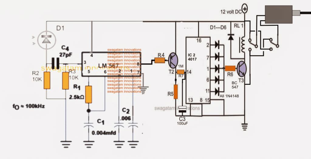
The above diagram shows a simple IR based remote receiver design, wherein the IC LM567 forms the IR frequency decoder while the IC 4017 forms the flip flop stage.
D1 is a photodiode sensor which converts the IR frequency from the IR transmitter into a correspondingly pulsating voltage across R2.
This pulsating voltage is sensed and recognized by the pin3 of the IC LM567, if the frequency of the pulse matches with the fixed frequency of the IC it instantly activates its output pin8 with a low logic pulse.
The IC frequency is fixed by selecting R1/C1 appropriately which becomes the unique code of that particular remote control system. Any value between 10 Hz to 500 kHz may be set using these RC timing components of the IC.
When a matching frequency is detected across R2, pin8 of the LM567 is rendered with a low signal.
This triggers the connected BC557 sending a positive pulse to pin14 of the IC 4017.
Pin14 being the clock pin of the IC 4017 generates a resulting shifting high across its shown outputs, depending on the initial status either a high or a blank signal is created at the base of the attached BC547 relay driver stage.
This enables the relay to toggle over the respective position forcing the solenoid device towards a locking or an unlocking position.
C3 is purposely introduced in order to delay the response of the relay toggling, this implies that the remote transmitter will need to be pressed for a few seconds in order to implement the above locking/unlocking procedures. This ensures that an intruder or a hacker is not able to influence the Rx through a varying/sweeping frequency generating device.
The IR Transmitter Circuit
The following image illustrates the IR transmitter handset for the above RX unit, which becomes the remote control handset for locking or unlocking the door.
The above Tx is a simple RC based two transistor oscillator, which may be applied as the Tx remote handset for the proposed IR door lock circuit.
The 3V is applied through a push button switch activating the pulses through the IR diode towards the photo diode of the above explained Rx circuit.
In this Tx circuit also the R and C components must be accordingly selected such that the transmitted frequency uniquely matches with the set frequency of the Rx circuit.
The relevant formulas may be studied in the following article
After assembling the proposed infrared remote controlled door lock circuit, the units may be tested externally to confirm the relay toggling in response to the Tx IR frequency.
Once this is done, the Rx circuit may be suitably enclosed inside a sturdy box and integrated with the door from the interior for the intended locking/unlocking
With over 50,000 comments answered so far, this is the only electronics website dedicated to solving all your circuit-related problems. If you’re stuck on a circuit, please leave your question in the comment box, and I will try to solve it ASAP!