Almost any digital circuit used in modern high-speed data communications needs some form of Schmitt trigger action on its inputs.
Why Schmitt Trigger is Used
The main purpose of a Schmitt trigger here is to eliminate noise and interference on data lines and provide a nice clean digital output with fast edge transitions.
The rise and fall times must be low enough in a digital output that it can be applied as inputs to the following stages in a circuit. (Many ICs have limitations of the type of edge transition that can appear on an input.)
The main advantage of Schmitt triggers here is that they clean up noisy signals while still maintaining a high data flow rate, unlike filters, which can filter out noise, but slow the data rate down significantly.
Schmitt triggers are also commonly found in circuits that need a waveform with slow edge transitions to be translated into a digital waveform with fast, clean edge transitions.
A Schmitt trigger can transform almost any analog waveform - such as a sine wave or sawtooth waveform - into an ON-OFF digital signal with fast edge transitions.Schmitt triggers are active digital devices with one input and one output, like a buffer or inverter.
Under operation, the digital output can either be high or low, and this output changes state only when its input voltage goes above or below two preset threshold voltage limits. If the output happens to be low, the output will not change to high unless the input signal goes above a certain upper threshold limit.
Likewise, if the output happens to be high, the output will not change to low until the input signal goes below certain lower threshold limit.
The lower threshold is somewhat lower than the upper threshold limit. Any kind of waveform can be applied to the input (sinusoidal waves, sawtooths, audio waveforms, pulses, etc.) as long as its amplitude is within the operating voltage range.
Diagarm to Explain Schmitt Trigger
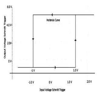
The diagram below shows the hysteresis resulting from the upper and lower input voltage threshold values. Any time the input is above the upper threshold limit, the output is high.
When the input is below the lower threshold, the output is low, and when the input signal voltage happens to be between the upper and lower threshold limits, the output retains its previous value, which can be either high or low.
The distance between the lower threshold and the upper threshold is called the hysteresis gap. The output always retains its previous state until the input changes sufficiently to trigger it to change. This is the reason for the “trigger” designation in the name.
The Schmitt trigger operates in much the same way as a bistable latch circuit or a bistable multivibrator, as it has an internal 1 bit memory, and changes its state depending on trigger conditions.

Using IC 74XX Series for Schmitt Trigger Operation
Texas Instruments provides Schmitt trigger functions in almost all of its technology families, from the old 74XX family to the latest AUP1T family.
These ICs can be packaged with either an inverting or non-inverting Schmitt trigger. Most Schmitt trigger devices, such as the 74HC14, have threshold levels at a fixed ratio of Vcc.
This might be adequate for most applications, but sometimes the threshold levels need to be changed depending on input signal conditions.
For example, the input signal range might be smaller than the fixed hysteresis gap. The threshold levels can be changed in ICs like the 74HC14 by connecting a negative feedback resistor from output to input along with another resistor connecting the input signal to the device input.
This provides the positive feedback needed for hysteresis, and the hysteresis gap can now be adjusted by changing the values of the two added resistors, or by using a potentiometer. The resistors should be of great enough value to keep the input impedance at a high level.
A Schmitt trigger is a simple concept, but it was not invented until 1934, while an American scientist by the name of Otto H. Schmitt was still a graduate student.
About Otto H. Schmitt
He was not an electrical engineer, as his studies were focused on biological engineering and biophysics. He came up with the idea of a Schmitt trigger as he was trying to engineer a device that would replicate the mechanism of neural impulse propagation in squid nerves.
His thesis describes a “thermionic trigger” that allows an analog signal to be converted to a digital signal, which is either full on or off (‘1’ or ‘0’).
Little did he know that major electronics companies like Microsoft, Texas Instruments, and NXP Semiconductors could not exist as they are today without this unique invention.
The Schmitt trigger turned out to be such an important invention that it is used in the input mechanisms of virtually every digital electronic device on the market.
What is a Schmitt Trigger
The concept of a Schmitt trigger is based around the idea of positive feedback, and the fact that any active circuit or device can be made to act like a Schmitt trigger by applying the positive feedback such that the loop gain is greater than one.
The output voltage of the active device is attenuated by a determined amount and applied as positive feedback to the input, which effectively adds the input signal to the attenuated output voltage.This creates a hysteresis action with upper and lower input voltage threshold values.
Most of the standard buffers, inverters, and comparators use only one threshold value. The output changes state as soon as the input waveform crosses this threshold in either direction.
How Schmitt Trigger Works
A noisy input signal or a signal with a slow waveform would appear on the output as a series of noise pulses.
A Schmitt trigger cleans this is up - after the output changes state as its input crosses a threshold, the threshold itself also changes, so now the input voltage has to move farther in the opposite direction to change state again.
Noise or interference on the input would not appear on the output unless its amplitude happens to be greater than the difference between the two threshold values.
Any analog signal, such a sinusoidal waveforms or audio signals, can be translated into a series of ON-OFF pulses with fast, clean edge transitions.There are three methods of implementing the positive feedback to form a Schmitt trigger circuit.
How Feedback Works in Schmitt Trigger
In the first configuration, the feedback is added directly to the input voltage, so the voltage has to shift by a greater amount in the opposite direction to cause another change in output.
This is commonly known as parallel positive feedback.
In the second configuration, the feedback is subtracted from the threshold voltage, which has the same effect as adding feedback to the input voltage.
This forms a series positive feedback circuit, and is sometimes called a dynamic threshold circuit. A resistor-divider network usually sets the threshold voltage, which is part of the input stage.
The first two circuits can easily be implemented via use of a single opamp or two transistors along with a few resistors. The third technique is a little more complex, and is different in that it doesn’t have any feedback to any part of the input stage.
This method uses two separate comparators for the two threshold limit values and a flip-flop as a 1 bit memory element. There is no positive feedback applied to the comparators, as they are contained within the memory element. Each of these three methods is explained in more detail in the following paragraphs.
All Schmitt triggers are active devices relying on positive feedback to achieve their hysteresis action. The output goes to 'high' whenever the input rises above a certain preset upper threshold limit, and goes to 'low' whenever the input drops below a lower threshold limit.
The output retains its previous value (low or high), when the input is between the two threshold limits.
This type of circuit is often used to clean up noisy signals, and convert an analogue waveform into a digital waveform (1’s and 0’s) with clean, fast edge transitions.
Types of Feedback in Schmitt trigger circuits
There are three methods typically used in implementing positive feedback to form a Schmitt trigger circuit. These methods are Parallel Feedback, Series Feedback, and Internal Feedback, and are discussed as follows.
The parallel and series feedback techniques are actually dual versions of the same feedback circuit type. Parallel Feedback A parallel feedback circuit is sometimes called a modified input voltage circuit.
In this circuit, the feedback is added directly to the input voltage, and does not affect the threshold voltage. As the feedback is added to the input when the output changes state, the input voltage has to shift by a greater amount in the opposite direction to cause further change in output.
If the output is low, and the input signal increases to the point where it crosses the threshold voltage and the output changes to high.
Part of this output is applied directly to the input through a feedback loop, which “helps” the output voltage stay in its new state.
This effectively increases the input voltage, which has same effect as lowering the threshold voltage.
The threshold voltage itself is not changed, but the input now has to move farther in the downward direction to change the output to a low state. Once the output is low, this same process repeats itself to get back to the high state.
This circuit does not have to use a differential amplifier, as any single-ended non-inverting amplifier will work.
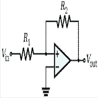
Both the input signal and the output feedback are applied to the non-inverting input of the amplifier through resistors, and these two resistors form a weighted parallel summer. If there is an inverting input, it is set to a constant reference voltage.
Examples of parallel feedback circuits are a collector-base coupled Schmitt trigger circuit or a non-inverting op-amp circuit, as shown:
Series Feedback
A dynamic threshold (series feedback) circuit operates in basically the same way as a parallel feedback circuit, except that the feedback from the output directly changes the threshold voltage instead of the input voltage.
The feedback is subtracted from the threshold voltage, which has the same effect as adding feedback to the input voltage. As soon as the input crosses the threshold voltage limit, the threshold voltage changes to the opposite value.
The input now has to change to a greater extent in the opposite direction to change the output state again. The output is isolated from the input voltage and only affects the threshold voltage.
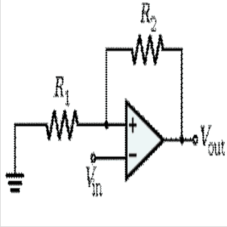
Therefore, the input resistance can be made much higher for this series circuit compared to a parallel circuit. This circuit is usually based on a differential amplifier where the input is connected to the inverting input and the output is connected to the non-inverting input through a resistor voltage divider.
The voltage divider sets the threshold values, and the loop acts like a series voltage summer. Examples of this type are the classic transistor emitter-coupled Schmitt trigger and an inverting op-amp circuit, as shown here:
Internal Feedback
In this configuration, a Schmitt trigger is created by using two separate comparators (without hysteresis) for the two threshold limits.
The outputs of these comparators are connected to the set and reset inputs of an RS flip-flop. The positive feedback is contained within the flip-flop, so there is no feedback to the comparators. The output of the RS flip-flop toggles high when the input goes above the upper threshold, and toggles low when the input goes below the lower threshold.
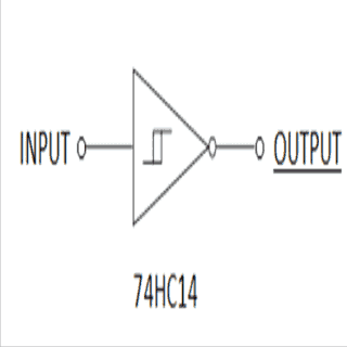
When the input is between upper and lower thresholds, the output retains its previous state. An example of a device that uses this technique is the 74HC14 made by NXP Semiconductors and Texas Instruments.
This part consists of an upper threshold comparator and a lower threshold comparator, which are used to set and reset an RS flip-flop. The 74HC14 Schmitt trigger is one of the most popular devices for interfacing real world signals with digital electronics.
The two threshold limits in this device are set at a fixed ratio of Vcc. This minimises the part count and keeps the circuit simple, but sometimes the threshold levels need to be changed for different kinds of input signal conditions.
For example, the input signal range might be smaller than the fixed hysteresis voltage range. The threshold levels can be changed in the 74HC14 by connecting a negative feedback resistor from the output to input, and another resistor connecting the input signal to the input.
This effectively reduces the fixed 30% positive feedback to some lower value, such as 15%. It is important to use high-value resistors for this (Mega-Ohm range) in order to keep the input resistance high.
Advantages of Schmitt trigger
Schmitt triggers serve a purpose in any kind of high-speed data communication system with some form of digital signal processing. Actually, they serve a dual purpose: to clean up noise and interference on data lines while still maintaining a high data flow rate, and to convert a random analogue waveform into an ON-OFF digital waveform with fast, clean edge transitions.
This provides an advantage over filters, which can filter out noise, but slow the data rate down significantly because of their limited bandwidth. Also, standard filters are not able to provide a nice, clean digital output with fast edge transitions when a slow input waveform is applied.
These two advantages of Schmitt triggers are explained in more detail as follows: Noisy Signal InputsThe effects of noise and interference are a major problem in digital systems as longer and longer cables are used and higher and higher data rates are required.
Some of the more common ways to reduce noise include using shielded cables, using twisted wires, matching impedances and reducing output impedances.
These techniques can be effective in reducing noise, but there will still be some noise left on an input line, and that could trigger unwanted signals within a circuit.
Most of the standard buffers, inverters, and comparators used in digital circuits have only one threshold value on the input. So, the output changes state as soon as the input waveform crosses this threshold in either direction.
If a random noise signal crosses this threshold point on an input multiple times, it will be seen on the output as a series of pulses. Also, a waveform with slow edge transitions could appear on the output as a series of oscillating noise pulses.
Sometimes a filter is used to reduce this extra noise, such as in an RC network. But any time a filter like this is used on the data path, it slows down the maximum data rate significantly. Filters block out noise, but they also block out high-frequency digital signals.
Schmitt trigger Filters
A Schmitt trigger cleans this is up. After the output changes its state as its input crosses a threshold, the threshold itself also changes, so then the input has to move farther in the opposite direction to cause another change in output.
Because of this hysteresis effect, using Schmitt triggers is probably the most effective way to reduce noise and interference problems in a digital circuit. Noise and interference problems can usually be solved, if not eliminated, by adding hysteresis on the input line in the form of a Schmitt trigger.
As long as the amplitude of the noise or interference on the input is less than the width of the hysteresis gap of the Schmitt trigger, there will be no effects of noise on the output.
Even if the amplitude is slightly greater, it should not affect the output unless the input signal is centered on the hysteresis gap.The threshold levels might have to be adjusted in order to achieve maximum noise elimination.
This can easily be done by changing the values of a resistor in the positive feedback network, or by using a potentiometer.
The main benefit that a Schmitt trigger provides over filters is that it doesn’t slow down the data rate, and actually speeds it up in some cases via conversion of slow waveforms into fast waveforms (faster edge transitions).Almost any digital IC on the market today uses some form of Schmitt trigger action (hysteresis) on its digital inputs.
These include MCUs, memory chips, logic gates and so on. Although these digital ICs might have hysteresis on their inputs, many of them also have limitations for their input rise and fall times displayed on their spec sheets, and these have to be taken into consideration. An ideal Schmitt trigger does not have any rise or fall time limitations on its input.
Slow Input Waveforms sometimes the hysteresis gap is too small, or there is only one threshold value (a non-Schmitt trigger device) where the output goes high if the input rises above the threshold, and the output goes low if the input signal falls below it.
In cases like these, there is a marginal area around the threshold, and a slow input signal can easily cause oscillations or excess current to flow through the circuit, which could even damage the device.These slow input signals can sometimes happen even in fast digital circuits under power up conditions or other conditions where a filter (such as an RC network) is used to feed signals to the inputs.
Problems of this type often occur within the “de-bounce” circuitry of manual switches, long cables or wiring, and heavily loaded circuits.
For example, if a slow ramp signal (integrator) is applied to a buffer and it crosses the single threshold point on the input, the output will change its state (from low to high, for example). This triggering action could cause extra current to be drawn from the power supply momentarily, and also lower the VCC power level slightly.
This change could be enough to cause the output to change its state again from high to low, as the buffer senses that the input crossed the threshold again (despite the input staying the same). This could repeat again in the opposite direction, so a series of oscillating pulse would appear on the output.
Using a Schmitt trigger in this instance will not only eliminate the oscillations, but it will also translate the slow edge transitions into a clean series of ON-OFF pulses with nearly vertical edge transitions. The output of a Schmitt trigger can then be used to as an input to the following device according to its rise and fall time specs.
(Although oscillations can be eliminated by using a Schmitt trigger, there could still be excess current flow in a transition, which may need to be corrected some other way.)
The Schmitt trigger is also found in cases where an analogue input, such as a sinusoidal waveform, audio waveform, or sawtooth waveform, needs to be converted into a square wave or some other type of ON-OFF digital signal with fast edge transitions.


Need Help? Please Leave a Comment! We value your input—Kindly keep it relevant to the above topic!