In this post I have explained 3 simple yet accurate infrared intruder alarm circuits using an infrared transmitter and an infrared receiver module. The transmitter and the receiver photo diodes used in the two modules are aligned in line at a distance of around 2 meters within the restricted area.
When a burglar tries to trespass the restricted area, he unknowingly crosses the IR beam cutting of the transmission link between the transmitter and the receiver, which activates the attached relay alarm sound.
The circuit is intended to be fitted inside an existing burglar security system. For distances of around 2 metres or less, the system is quite simple and does not require any extra lenses or filters.
Such small range is generally enough to cover room doors, corridors, and other areas.
The device is made up of two circuits: one that generates an infrared beam and another that detects it and sounds an alert if the signal is broken.
A pulsed infrared beam is employed, as is the case with many of these technologies of this kind.
A modulated beam may easily be determined against ambient infrared radiation, facilitating the use of a low-power beam.
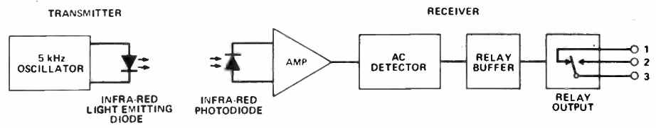
1) Block Diagram
The first design in the following image shows the infrared transmitter/receiver block diagram. Any entity that comes between the two devices will disrupt the IR beam, causing the relay and the alarm system attached to it to switch ON.
Intruder Alarm IR (infrared) Transmitter Circuit
The transmitter is constructed around the well-known 555 timer IC and operates in astable mode. The timing elements are R1, R2, and C2, which provide a 5.25kHz operational frequency.
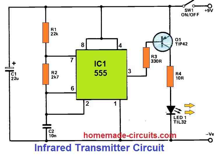
The output turns high while C2 charges up through the relatively high resistance of R1+R2, and turns low while C2 discharges through the lower resistance of R2 and an internal transistor of IC1.
Due to this operation, a conventional 555 oscillator doesn't really generate a genuine squarewave output because the output is in the high state for a much longer duration than the low state.
The parameters utilized in this example result in an output that is is able to stay in the low state only around 10% of the time period. Q1 is switched on through the base current it gets via R3 throughout these short negative output bursts.
By means of the current limiting resistor R4, it then transfers a current of around 500 mA to infrared LED1. However, the net current passing through LED1 is hardly around 50 mA.
Thus, this system produces quite powerful infrared pulses while consuming a relatively modest overall current. LED1 does not use the visible light spectrum for generating the intended infrared rays.
Intruder Alarm IR(infrared) Receiver Circuit
Infrared pulses are intercepted by photo-diode LED1 at the receiver end. This is applied through the supply rails via load resistor R1.
The leakage current through LED1 increases temporarily as a result of the infrared pulses, producing a sequence of tiny voltage pulses at the intersection of R1 and LED1.
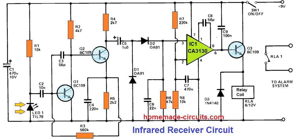
C2 feeds these pulses to the input of a basic high gain amplifier, which employs Q1 and Q2 in a two-stage directly coupled configuration. C2 and C4 are intentionally set to low levels to ensure that the circuit gets an inferior low-frequency response.
This ensures that 50 Hertz signals generated by LED1 due to the infrared radiation leakage from the mains-powered lights are effectively rejected.
However, at the significantly higher working frequency of the transmitter circuit, the circuit seems to provide a larger gain.
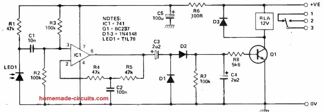
C5 connects the amplifier's output to a rectifier and smoothing circuit made up of D1, D2, C6, and R6. This circuit's positive bias is supplied into one of the operational amplifier IC1's inputs.
R7 and R8 provide a bias voltage to the other input. In most cases, the inverting input's fixed bias would be larger than the bias supplied to the non-inverting input.
The IC1 is configured like a comparator, and its output switches high while under situations, activating the relay coil.
The separate buffer stage Q3 is employed to supply the relatively high driving current necessary.
If an intruder briefly disrupts the beam, the charge on C6 rapidly decays, dropping IC1's non-inverting input potential below the inverting input.
The output of IC1 is therefore turned low, causing the relay to turn off, which opens the contacts of relay RLA1, and the central security system is activated.
How to Set Up the Intruder Alarm
To set up the above explained infrared intruder alarm circuit, you simply have to align the transmitter infrared beam with the receiver photodiode, such that the receiver photodiode is able to remain activated with the transmitter infrared signal.
The above set up can be installed in front of doors, windows, gardens or any place that needs to be monitored against an intrusion.
In this situation, if an intruder tried to cross the path, it momentarily breaks the infrared beam, which in turn causes the receiver to deactivate for a moment.
This instantly causes the receiver relay to activate and sound the connected alarm.
2) Another Design using IC 555 and IC 741
The second design of an IR intruder alarm circuit can be seen in the following images. The idea was contributed by one of the avid readers of this blog Mr. Amit.
Just like the above concept this design also has a transmitter and receiver units which simply needs to be aligned in line so that the IR waves from the transmitter circuit reaches the photodiode of the receiver and keeps its relay activated.
As soon as a potential intruder tries to cross the path, it ends up breaking the IR beam which causes the receiver unit to deactivate for a moment and sound the connected alarm.
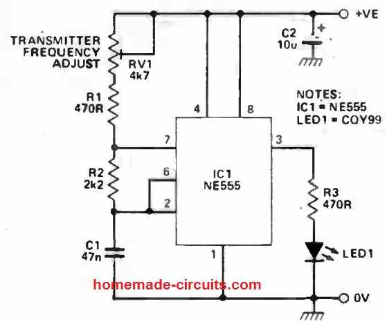
Transmitter Circuit
The following depicts the transmitter's real circuit diagram. It's built on a NE555 timer that's been set up as an astable multivibrator.
This indicates that the infrared emitter, LED1, is turned on and off several times per second - the frequency of oscillation is roughly 5KHz for the values given.
There are several benefits of using a pulsed beam versus a continuous emission. To begin, it encodes the IR pulse in a way that the transmitter can understand and distinguish the signal from the impacts of other emissions, for example from LED, CFL lights in the close surroundings.
Furthermore, by selecting a high frequency, it becomes possible to AC couple the transmitter circuit and enable it to be resistant to gradual changes in ambient light levels, such as transitioning from day to night.
Thirdly, pulsing the transmitter saves power, which is beneficial when the transmitter is powered by batteries.
The transmission frequency may be changed using the RV1 preset potentiometer, allowing for some tuning up based on the practical positions of the transmitter and receiver.
Receiver Circuit
The next figure below depicts the receiver's circuit. LED 1 is an infrared receiver diode that has been reverse biassed by R1.
When infrared light strikes a diode, it causes an increase in minority carriers and a commensurate boost in diode conductivity.
This results in a voltage drop at the junction of R1 and LED1. C1 then AC couples the output to the op-amp.
This serves to provide the receiver with a high level of tolerance to fluctuations in ambient light levels as well as the impacts of incandescent lights, CFL bulbs and fluorescent lights.
IC1 is hooked up as an a non -inverting AC amplifier, while R2 and R3 bias the input to 50% power supply range.
The combination of R4, R5, and C2 determines the amplifier's gain.
The gain of the amplifier is near to unity at lower frequency, but as the frequency of the input signal increases, the impedance of C2 decreases, raising the average gain of the amplifier, such that at 5KHz or so of the transmitter signal the amplifier is fixed with a gain of many thousands.
The output of IC1 will become an AC signal of roughly 5KHz whenever the transmitted signal is detected by the receiver.
C3 subsequently AC couples this output signal to the voltage doubler circuitry of D1, D2, adequately charging the filter capacitor C4 to switch ON the transistor Q1 and the relay.
C4 discharges through R7 and the relay switches off when the transmission is cut-off or disturbed.
R6 and C5 offer further power supply decoupling to the amplifier, eliminating any spikes generated by the relay switching on and off. Back EMF shielding is provided by Diode D3.
3) Long Range TSOP1738 IR Sensor Based Alarm Circuit
The following paragraphs discusses the third design of an infrared burglar alarm for long range detection.
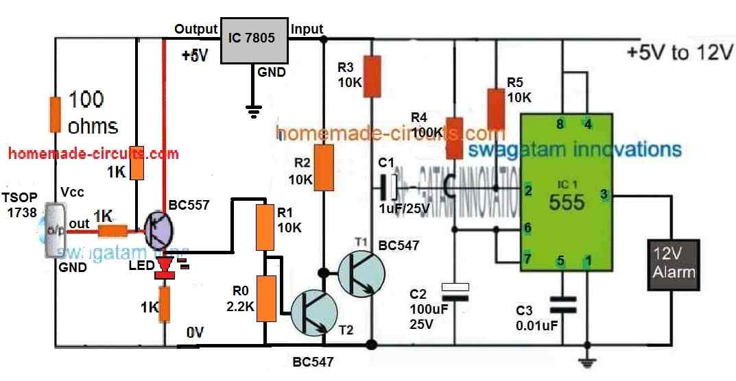
NOTE: In the above diagram please make sure to add a 10uF/25V between the collector of BC557 and the ground line, this is very important.
Introduction
The IR signal-based alarm circuit is designed to detect the interruption of a 38 kHz IR signal and trigger an alarm in response.
The circuit utilizes an IC 555-based monostable multivibrator (one-shot) to control the alarm activation.
The activation of the monostable circuit is accomplished by momentarily triggering Pin 2 of the IC 555 through a capacitor. This triggering is facilitated by a BC547 transistor connected with the capacitor.
IC 555 Monostable
The heart of the circuit is the IC 555 monostable multivibrator. The monostable mode allows the IC to remain in a stable state until it receives a trigger signal.
Upon receiving the trigger, the IC produces a pulse of fixed duration at its output (Pin 3). The duration of the output pulse is determined by the values of the resistors and capacitors connected to the IC.
Triggering the IC 555 Monostable
To activate the IC 555 monostable, a BC547 transistor is utilized. The BC547 transistor acts as a switch to momentarily trigger Pin 2 of the IC 555 through a capacitor.
When the BC547 transistor is switched on, it allows the capacitor to charge up, and when it switches off, the charged capacitor discharges rapidly, creating a momentary trigger at Pin 2 of the IC.
Second BC547 Transistor
The second BC547 transistor plays a crucial role in maintaining the IC 555 monostable in a standby mode. Its collector is connected to the base of the first BC547 transistor.
As long as the second BC547 transistor remains switched on, it keeps the first BC547 transistor switched off. This ensures that the IC 555 monostable remains deactivated and in a standby mode.
Continuous IR Signal
The continuous 38 kHz IR signal is generated and incident on a TSOP1738 IR sensor IC. The TSOP1738 IC is specifically designed to receive and detect IR signals at a frequency of 38 kHz.
When the TSOP1738 IC receives the continuous IR signal, it keeps the second BC547 transistor switched on, which, in turn, keeps the first BC547 transistor switched off. This maintains the IC 555 monostable in standby mode, with the alarm deactivated.
Interruption Detection
Any interruption in the 38 kHz IR signal, caused by an animal or an intruder, results in the second BC547 transistor switching off.
This action causes the first BC547 transistor to switch on, triggering the IC 555 monostable. The momentary trigger at Pin 2 of the IC 555 activates it, causing the output relay to turn on, thus activating the alarm.
RC Network
The timing of the IC 555 monostable's output pulse duration is determined by the values of the resistors and capacitors connected to the IC.
This configuration forms an RC network, where R represents resistors and C represents capacitors. The specific values of the resistors and capacitors are chosen to achieve the desired time delay for the alarm activation.
Output Relay and Alarm
The output of the IC 555 monostable (Pin 3) is connected to a relay, which acts as a switch. When the IC is triggered, it produces a high output at Pin 3, activating the relay.
The relay, in turn, controls the alarm circuit, allowing power to flow through it and generate the desired alarm sound or signal. The duration of the alarm is determined by the timing components in the IC 555 monostable circuit.
IR Transmitter (IC 555 Astable)
To generate the continuous 38 kHz IR signal, another IC 555 is utilized in astable mode.
The IC 555 is configured as an astable multivibrator, which generates a continuous square wave output with a frequency determined by the timing components connected to it.In this case, the timing components are selected to produce a 38 kHz frequency.
Astable Multivibrator Configuration
The IC 555's astable design controls the time and frequency of the square wave output with resistors (R1, R2) and capacitors (C1, C2). A 38 kHz frequency may be obtained by selecting acceptable values for R1, R2, C1, and C2.
The square wave output from Pin 3 of the IC 555 is connected to an IR LED, which emits the continuous 38 kHz IR signal.
IR LED and TSOP1738
The IR LED connected to the output of the IC 555 astable acts as the transmitter, emitting the 38 kHz IR signal. The TSOP1738 IR sensor IC is positioned to receive this IR signal.
The TSOP1738 IC is designed to detect IR signals at a frequency of 38 kHz. It demodulates the received IR signal and provides an output to control the second BC547 transistor.
As long as the 38 kHz IR signal is incident on the TSOP1738 IC, it keeps the second BC547 transistor switched on, maintaining the IC 555 monostable in standby mode.
Conclusion
In summary, the IR signal-based alarm circuit utilizes an IC 555 monostable triggered by a BC547 transistor to control the alarm activation.
The continuous 38 kHz IR signal, generated by another IC 555 in astable mode, keeps the second BC547 transistor switched on. Any interruption in the IR signal triggers the IC 555 monostable, activating the alarm through an output relay.
Dear Sir swagatam
Hello. Hope you are fine and healthy
Unfortunately, I couldn’t find the circuit that I had seen on your site for escaping farm animals, so I have to leave it here. The circuit uses a 0.2 microfarad 400V capacitor placed across the 220V power line. I need a circuit that will sound an alarm at home when an animal touches the fence around the farm. I will be very happy and grateful if you can help me.
Wish you all the best
Truly
Mike
Hi Mike,
The 0.22uF fence charger circuit which you are referring to was removed by me since it involved a direct 220V AC mains supply. However I replaced it with a transformer based design which you can find at the end of the following post:
https://www.homemade-circuits.com/homemade-fence-charger-energizer/
Creating an alarm circuit when fence wire is touched can be quite difficult, instead I would recommend using a PIR motion sensor for better response and easier configuration:
https://www.homemade-circuits.com/pir-burglar-alarm-circuit/
Dear Sir Swagatam
Hello
Thank you very much for your excellent and comprehensive answer and valuable tips. Your high voltage circuits are amazing and I will do and share the results. However, I am sorry to say that none of the three PIR modules that I prepared a month ago, and they were of the same type that you have used in the circuit that you suggested to me, performed well outside the house (and not against the sun), maybe because of the poor quality of these modules that can be purchased in my country for half a dollar.
You will make me very happy and grateful if you please tell me whether it is scientifically possible if I connect two strands of wire to a point in the fence that is connected to of the 0.22uF fence charger circuit ( and I am using it now ) and reduce the 220v supply by adding resistance, capacitor and zener diode to 3 v; then connect the neutral wire of the output 3v to the input of a touch control circuit, will the circuit work?
Truly yours
Mike
Thank you Mike,
Unfortunately, PIR sensors cannot be used in sunlight, they will not work. PIRs can word correctly only in shade or at night time.
The circuit idea that you are referring to might not work according to me, or it might result in a lot of false triggering.
Thanks a lot for your kind response dear Sir Swagatam. I used PIRs in shade too, but they did not work correctly. I have learned a lot from your very interesting site and admire and value a lot this spirit of helping others in you.
God bless you
Best regards
Mike
No problem Mike, I appreciate your kind feedback. So it seems a PIR can work correctly only if it is indoors where there’s no traces of any sunlight.
Glad you found this site helpful. God bless you too. All the best to you.
Hello Sir Swagatam
would you please confirm with me if there is a diode substitution available for OA91, which is rare.
Wish you all the best
Max
Hello Max,
You can consider using a 1N34A or a 1N60 diode, which are both Germanium point-contact diodes commonly available today.
Hello Sir Swagatam
Thank you very much
All the best to you
Max
You are most welcome Max.
Dear Sir Swagatam,
Hello, I hope this message finds you well. Please accept my apologies for the delayed response to your previous message. I have been searching for IR sensors during these days and have finally found a few that may be suitable for assembling the circuit.
I have attached a picture of the sensors to your email. Unfortunately, they do not have any part numbers, so I am unsure whether each couple will match or be suitable for use in the circuits. However, the three-pin sensor is a dual sensor, as you are certainly aware.
Please let me know if you have any specific instructions or if there is anything else I can do in this regard. Additionally, if you require me to substitute any of these sensors or if any couple of them will suffice, please inform me.
Best regards,
Max
Thank you Max,
I saw the picture of the photodiodes you sent me. The LED type photodiodes will work but these have very low distance range so they are not good. The 3 pin sensor could be TSOP1738 which have high distance range but requires a 38 kHz frequency from the transmitter to activate. You can try the TSOP based circuit presented in the above article.
Here’s another article which provide more information about the TSOP sensor.
https://www.homemade-circuits.com/how-to-connect-tsop1738-ir-sensor/
Hello Dear Swagatam
Thank you for you useful reply and the useful link you offered. I will try and will say you the results.
Best regards
Max
No problem Max, all the best to you.
Dear Sir Swagatam
Hello, I hope this letter finds you well. I am writing to provide an update on the project titled “TSOP1738 IR Sensor Based Alarm Circuit” that I have been working on.
I have successfully assembled the circuit today, using a 3-pin IR sensor, although there was no part number printed on it. I placed the components on a breadboard and connected the output of the Ne555 to a green LED instead of a relay.
Upon connecting the circuit to a 9V power supply, I observed that the green LED illuminated for exactly 11 seconds before turning off. I repeated this process several times, and the outcome remained consistent. Meanwhile, the red LED, which is connected to the collector of the BC557 transistor, remained lit continuously while the circuit was connected to the power supply.
In an attempt to troubleshoot the issue, I made an adjustment by twisting the IR sensor by 180 degrees. Specifically, I connected the pin marked as “minus” to the 1K resistor, and the pin marked as “out” to the ground. However, this alteration did not yield any changes, and the circuit still did not respond to motion.
Based on these observations, I have reached the conclusion that the 3-pin IR sensor I purchased (which was the only one available in the market) is not the TSOP1738 model as required for the project.
I would like to express my sincere gratitude for all the assistance you have provided so far. Your guidance has been invaluable throughout this process and I will always remember it.
Best regards,
Max
Thank you Dear Max,
I appreciate your efforts to test the circuit with your existing 3 pin IR sensors.
If the red LED is constantly ON means the 3 pin IR sensor is not switching ON/OFF to the 38 KHz frequency applied from a TV remote or from a 555 IC transmitter.
I hope you will be able to replace the IR sensor and get the intended response from your circuit soon.
All the best to you.
Dear Sir Swagatam
I am writing to express my gratitude for your exceptional sense of helpfulness, encouragement, and teaching skills that you have imparted to your visitors. Your dedication and hard work are truly admirable, and I wish you all the best.
I tested the project using both TV and satellite remote controls, just now but I did not get a reaction. I was wondering if you could clarify something for me. I understand that the 3-pin IR sensors like the one I have used act as both a transmitter and a receiver, while the 2-pin IR diodes have one as a transmitter and the other as a receiver. Should I assemble an IR transmitter for this project? which one?
Thank you for your time and assistance.
Sincerely,
Max
Thank you so much Max, for your kind words!
The TSOP1738 works only like a receiver, not like a transmitter.
First you can build a basic circuit to test whether your TSOP sensor is working correctly or not using a TV remote control as the transmitter.
If you want to build a separate transmitter circuit then you will have to build a 555 Ic based transmitter adjusted to produce a 38 kHz frequency through a transmitter photodiode.
The basic circuit operation and other details for the TSOP1738 is provided in the following article:
https://www.homemade-circuits.com/how-to-connect-tsop1738-ir-sensor/
I hope this will help you.
A video clip is also shown in the above article.
Dear Sir Swagatam
Hello. I hope you are doing well.
I searched through my collection of used electronic components a few hours ago and came across an IR sensor that is larger in dimensions than the one I had purchased earlier. I have sent you a picture of the sensor via email for your reference.
Using the circuit you provided in your tutorial titled “Basic Connection Details of TSOP1738 in a Circuit,” I successfully assembled the circuit and was delighted to see that it responded to commands from my TV remote, just as demonstrated in your video.
Encouraged by this result, I replaced the IR sensor in the project titled “TSOP1738 IR Sensor Based Alarm Circuit,” which I had completed yesterday, with the aforementioned used sensor. I then connected the circuit to a 9V power supply. Initially, the green LED (substituted for the relay) lit up for approximately 11 seconds and then turned off. I also noticed that every time I pressed a key on the remote, the circuit received the signals and the red LED blinked simultaneously. However, the green LED remained off throughout. I am wondering if this behavior is expected and if everything is functioning correctly, or if there might still be an underlying issue.
Additionally, I would greatly appreciate your recommendation for a suitable transmitter circuit to complement this project.
Thank you so much for all your attention and assistance.
Best regards,
Max
Thank you so much Max,
I saw your email, and the picture indeed looks like it is a TSOP1738
I am glad your TSOP1738 sensor is working now.
As per the information it seems you have integrated the sensor in the following circuit. In this circuit if the RED LED blinks then T2 should be triggered ON. Here we want T2 to remain triggered ON as long as the 38 kHz IR is focused on the sensor. As soon as the IR frequency is interrupted, T2 is supposed to switch OFF and trn ON T1. When T1 is turned ON, the 555 monostable becomes active and triggers ON the output load for 11 seconds. You can try increasing the RED LED series resistor from 1K to 10K and check whether this helps to switch ON the T2 or not. Also please connect a 10uF capacitor between the collector of BC557 and the ground line.
" rel="ugc">
For the transmitter circuit you can try the following circuit. Check whether the parts are able to generate the required 38 kHz frequency or not, through the IR photodiode:
" rel="ugc">
Hello, dear Sir SWagatam . Following your instruction, I replaced the 1k resistor with a 10k resistor, but the performance did not improved. however, when I added a 10uF capacitor between the collector of the BC557 transistor and the ground line, the issue was resolved and the circuit started working perfectly. This means that when I interrupted the IR frequency of the TV remote control aimed at the sensor, the 555 monostable became active and triggered the output load to turn on for 11 seconds. It is marvelous, dear Swagatam.
Thank you very much for your valuable and useful instructions. You were right, Sir – I integrated the TSOP1738 sensor into the circuit that you provided at this address:
" rel="ugc">
Nevertheless, there is still an unresolved issue. The last time I searched for COY99 in various stores, no shop had it, nor did they have the TSOP1738. I have little hope of finding COY99. If you know of a suitable alternative, I would greatly appreciate your guidance in this matter. Otherwise, I may have to rely on the hope of finding a second-hand TV remote and using it’s IR sensor, hoping that it is in good condition.
Once again, I express my deepest gratitude for your kindness and invaluable assistance.
Yours faithfully,
Max
That is wonderful Max,
I am so glad you could succeed with the mentioned project.
The COY99 is just an ordinary IR transmitter photodiode.
You can replace this photodiode with any of the transmitter photodiodes which you already have with you. Just make sure that the photodiode is a transmitter photodiode and not a receiver photodiode.
I greatly appreciate your kind words!
Dear Sir Swagatam
I thank you very much for your kind words, too. I tried the transmitter circuit you suggested with 2 transmitter photo diodes that I had recently provided but the receiver did not respond them. I’ll buy another ones and try it again and I hope it answers.
All the best to you
yours faithfully
Max
Dear Sir Swagatam
Hello, I hope you are doing well
A few hours ago, I wrote to you regarding my two transmitter photo diodes that were not functioning even though they were healthy (I apologize you).however upon further inspection, I realized that I had made an error by not connecting pin 2 and 6 of the IC555 of transmitter circuit to each other. After resolving this issue, I expected that the green LED would turn on when an intruder interrupted the signals of the IR transmitter. However, I have noticed that the LED or something else appears to be behaving in the opposite manner. When my hand is located between the transmitter and receiver diodes, the IC555 has no output. As soon as I remove my hand, the red LED blinks only once, and the green LED turns on and remains on for 11 seconds. I would greatly appreciate any insights you may have regarding the reason for this behavior. Thank you for your assistance.
regards
Max
No problem Max, I will try to help!
It is happening because of the T1/T2 arrangement.
Your hand action or the obstacle action should be actually implemented in the opposite way for this circuit to work normally.
Meaning, you must initially allow the 38 kHz frequency to remain focused on the TSOP sensor, this will cause the RED LED to remain blinking ON and will ensure that T2 is ON and T1 is OFF.
After this if you put an obstacle between the 38 KHz focus then the RED LED will shut off, which will shut off T2 and switch ON T1.
Once T1 is switched ON it will keep the monostable switched ON for 11 seconds.
But the main thing is that the RED LED should keep blinking as long as the 38 kHz is focused on it. That would ensure that the circuit is in the stand by mode and any momentary obstacle will switch ON the alarm for 11 seconds.
Dear Sir Swagatm
Thank you very much for taking the time to explain what happens when two IR diodes are focused on each other. Your patience and clear explanation are much appreciated. Over the past two days, I realized that the IR TSOP part number I used was TSOP1238, which may have been the reason for the circuit malfunctioning. I got a HS0038-A4 with the same size and shape as the TSOP1238 today and tested it. It is functioning well as you described. I would like to share with you some important tips that I have discovered during my testing:
1. When the two IR diodes are focused on each other at a distance of about 20 cm, the red LED lights up and does not blink. When an obstacle is placed between them, the red LED turns off immediately, and the monostable switches on for 11 seconds.
2. If the distance between the two IR diodes is increased beyond 20 cm, the red LED will appear off, but it is still on. If an obstacle is placed between them, the monostable will switch on again for 11 minutes. I tested the circuit up to a distance of approximately 200 cm, and the the circuit behaved as before.
3. One important observation is that when I aim the TV remote at the IR receiver at any distance, even up to 500 cm, the red LED blinks constantly, just as you described in your explanation.
4. Based on my testing, I believe that using a TV remote is the best option for this project due to the strength of the signal transmission. However, if it is possible to amplify the transmitter signals, with one or two transistors that would be great.
Once again, thank you for your kindness and assistance. Your insights were invaluable in helping me troubleshoot my circuit.
Best regards,
Max
Thank you so much Max,
I greatly appreciate your feedback and very useful observations. I am sure your observations will be of immense help to all the other blog visitors.
Regarding using a TV remote, yes TV remote works the best even though it uses only 3V battery supply. The 555 IC uses 9V and can supply more than 100 mA to the IR LED but still its amplification is not as good as as the TV remote, which is confusing and difficult to figure out.
If you have decided to use a TV remote as the transmitter, that’s a good and a convenient choice.
All the best to you!
Hello, dear Sir Swagatam
Thank you so much for your kind words and for appreciating my feedback. I am glad that my observations could be helpful for other visitors of your blog.
It is an honor to be able to contribute in a small way to your valuable work. Your insightful posts and well-written blog have helped me learn many useful things, so I wanted to offer my perspective to help improve it further.
I wish you continued success with your blog and all your future endeavors.
Again, thank you so very much for your kind words of appreciation. It was my pleasure to provide some observations that could be of help. I wish you all the best moving forward!
Sincerely,
Max
You are most welcome Max. Your kind words are much appreciated.
Perfectly crafted circuits especially the Infrared Receiver.
Glad you found it useful!