In this post we investigate the technical specifications and pinout details of the IC L293 which is a versatile quad half-H driver IC, and can be used for implementing many interesting motor driver based circuit applications, such as for operating motors, solenoids and other inductive loads (4 units separately or in pairs through push-pull mode).
How it Works
The IC L293 basically includes a two pairs of outputs which can be be independently used for operating two separate loads in a push pull mode or in a bidirectional manner, also referred to as totem pole mode.Alternatively these couple of pair of outputs can be individually used for operating 4 individual loads in a unidirectional manner.
The above operations of the loads is controlled through corresponding input pinouts, triggered from a external oscillator circuit or a PWM source.
For example if the load is required to be operated in a totem pole manner, the corresponding inputs of the two driver stages of the IC could be triggered from an external oscillator such as through a couple of NAND gates, wherein one gate could be wired as an oscillator while the other as an inverter.
The two anti-phase signals from these NAND gates then could be connected with the inputs of the L293 for operating the relevant outputs in a totem pole (push-pull) manner, which in turn would run the connected load in the same fashion.
Pinouts assignment of the IC L293
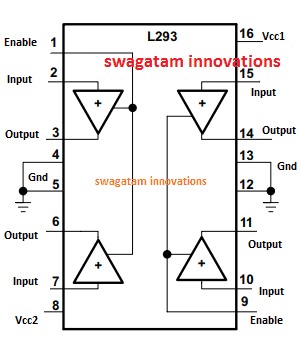
Now I have explained the pinout functions of the IC L293 by referring to the following diagram and from the following explanation:
Pin#2 is the control input, which controls the output pin#3.
Similarly, pin#7 is the control input for the output pin#6.
Pin#1 is used for either enabling or disabling the above sets of pinouts. A positive at pin#1 keeps the above sets of pinouts enabled and active, while a negative or 0V supply instantly disables them.
Quite identically, Pin#15 and pin#10 become the control inputs for the corresponding pin#14 and pin#11 outputs, and these remain operational only as long as pin#9 is held at positive logic and is disabled when a 0V logic is applied on this pinout.
As explained previously, pin#3 and pin#6 can be used as totem pole pairs by feeding an anti-phase logic signal on their input pin#7 and pin#2. Meaning, when pin#2 is being fed with a positive logic, pin#7 must be at a negative logic and vice versa.
This will allow the outputs pin#6 and pin#3 to be operate the connected load in a corresponding direction, and conversely when the input logic signals are reversed, the load polarity is also reversed and it will start rotating in the opposite direction.
If this sequence is rapidly switched then the load operates correspondingly in a to-and-fro manner or in a push pull manner.
The above operation can be replicated across the other side pair of drivers also.
The Vcc or the supply positive inputs for the IC are configured independently for two different supply inputs.
Pin#16, (Vcc1) is used for operating the enable pinouts and for operating other internal logic stages of the IC, and this could be supplied with an input of 5V, although maximum limitation is 36V
Pin#8, (Vcc2) is specifically used for powering the motors, and this can be fed with anything from 4.5V to 36V
Electrical Specification of the IC L293
The IC L293 is designed to operate with a any supply between 4.5V and 36V, with a maximum current handling specification of not more than 1 amp (2 Amp in pulse mode, 5ms max)
Therefore any load within the above mentioned specifications can be operated across the discussed outputs of the IC L293.
The Input control logic should not be exceeded above 7V, whether as a continuous supply or PWM supply.
Using L293 IC for Motor Control Application
Now I have explained how to implement motor controller circuits using the IC L293 through different modes of operations, and by using as many as 4 motors with separate control facility.
In our previous post we studied the pinout and functioning details of the IC L293, here I have explained how the same IC can be used for controlling motors through specific modes and configurations.
Control Modes
The IC L293 can be used for controlling motors in the following modes:
1) 4 motors through independent PWM inputs.
2) 2 Motors in a bidirectional or totem pole mode with speed control through PWM
3) One 2-phase BLDC motor using PWM input
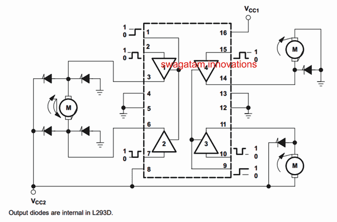
The image below shows how the IC could be used for controlling motors with independent controls, and also how a single motor could be used for achieving a bidirectional control:

The left side of the IC shows a motor being configured to work in the bidirectional mode. To ensure that the motor spins in one of the selected directions, pin#1 and pin#7 must be applied with an anti-phase 5V DC input. To change the direction of the motor rotation, this 5V polarity could be changed across the mentioned input pinouts.
Pin#1 must be held at logic high in order to keep the motor and the IC functioning enabled, a logic 0 here will instantly stop the motor.
The supply at the control input pinouts could be in the form of a PWM, this could be additionally used for controlling the speed of the motor from 0 to maximum simply by varying the PWM duty cycle.
The right side of the IC depicts an arrangement wherein a couple of motors are controlled independently through independent PWM inputs at the respective pin#15 and pin#10.
Pin#9 must be held at logic high in order to keep the motor and the IC functioning. A logic zero at this pinout will instantly stop and disable the function of the attached motors.
Since the left side and the right side sections of the IC are identical with their pinout functioning details, the shown arrangement of the motors could be swapped across the relevant pinouts to achieve identical functioning as explained above, meaning two individual motors could be connected at the left side of the IC exactly as implemented at the right side of the IC in the diagram.
Similarly the bidirectional system could be incorporated at the right side of the IC pinouts exactly as achieved at the left side of the IC in the above shown diagram.
The above example shows how the IC L293 can be used for controlling 4 motors individually, or 2 motors in a bidirectional mode, and how the speed also can be controlled using a PWM feed at the relevant input pinouts of the IC.
Using L293 to control a 2-phase BLDC motor

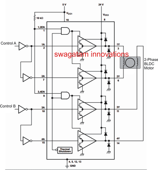
In the above image we can see how the IC L293 can be configured to control a 2-phase BLDC motor using the indicated pinouts and through a couple of control inputs shown as control A and control B.
A single 2-phase motor can be seen connected across the outputs of the IC, while the inputs are wired with a set of NOT gates which become responsible for creating the required anti-phase input logic for the motor control.
Control A and Control B points may be subjected to an alternating logic for enabling the 2-phase motor to rotate correctly.
The polarity of the alternating logic decides the rotational direction of the motor.
For achieving a linear speed control on the motor, a PWM form of logic could be implemented across the control A and control B inputs and its duty cycle could be varied for achieving the desired speed control on the connected motor.
If you have further doubts regarding the technical specifications, or the datasheet or the pinout details of the IC, you can always feel free to comment below for instant replies.

