

In this post, I have explained a simple laser GSM call alert security circuit which immediately calls the master as soon as an intruder is detected through a laser beam interruption.
The idea was requested by Mr. Roldan.
Circuit Objectives and Requirements
I am not an electronic engineer, but I can manage to troubleshoot minor electronic problems. I also have a basic knowledge on electronic schematics. I have already scans all your schematics about cell phone projects, but still I did not found the right project I wanted to build.
My request :
1.) A security alarm (i.e. burglar alarm) using laser, once that an intruder lurks in the perimeter it will eventually trigger/dial my cellphone, same as the idea of your CELL PHONE DOOR LOCK CIRCUIT. Instead of pushing the car central lock instrument, it will dial my number thru a GSM cell phone. so that I am aware that somebody is/were inside my house. I am always away from my house.
2.) I am thinking about using 2 cell phone, 1 unit is for the alarm system that will dial me in case of an intruder is inside.
Hoping for your kind consideration about my request sir, till next.
The Design
In one of my earlier posts I have already presented a Cell Phone Call Alert Security System Circuit designed to alert the user whenever an intrusion was detected, it employs the IC 4060 for the procedures. This circuit was inspired from yet another earlier article titled car GSM security circuit.
The present design also is based on a similar principle, however it utilizes an IC 555 and a small delay timer for implementing the functions making the circuit much simpler than the earlier concepts.
The following diagram shows the detailed configuration, let's try to understand it further through the given explanations:

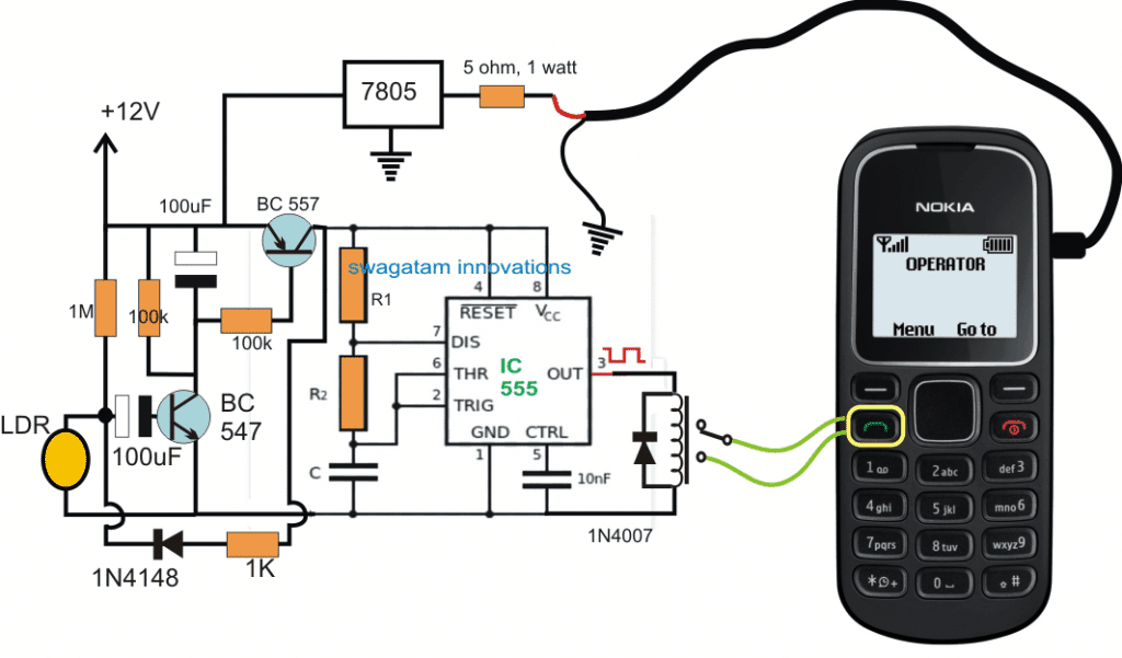
The Delay Output from IC 555 can be obtained by solving the following formulas:
On Time Output = 0.7(R1 + R2)C
How it Works
Referring to the above shown laser activated GSM call security circuit, we can see that the IC 555 is configured as a standard astable.
The 555 astable is powered through a delay OFF timer circuit which is in turn attached with an LDR trigger.
The LDR is supposed to be focused with a laser beam aligned across the restricted zone.
As long as the laser beam remains focused on the LDR, the resistance of the LDR is held sufficiently low with respect to the associated 1 M resistor.
However in an event where the laser gets interrupted, which might happen while an intruder tries to trespass the restricted zone, the LDR suddenly experiences a high resistance allowing the transistor BC547 base to acquire a triggering pulse through the 1M resistor and the associated 100uF capacitor.
This in turn activates BC557 hard into conduction and simultaneously charges the upper 100uF capacitor to the optimal limit.
Once the above takes place the BC547 is no longer required to conduct and in fact it stops conducting due to its base 100uF capacitor acquiring full charge and/or due to the restoration of the laser beam on the LDR (as the intruder crosses over to the other end)
The BC557 continues to conduct from the charge accumulated in the upper 100uF, and powers the IC 555 such that it is able to produce around three pulses to the relay which responds to this and clicks thrice and then stops.
The above three pulse limit may be achieved by suitably adjusting the two 100uF capacitor values such that the delay timer conducts for a period just enough to allow the IC 555 to produce those 3 pulses, after which the BC557 may be expected to switch OFF, along with the the IC 555 and the relay.
R1, R2, and C1 may also need to be calculated for allowing 0.5 second pulse from the astable, meaning the 3 pulses should not take more than 1.5 seconds to complete
The relay contacts can be seen integrated with the "call button" of a mobile phone which is used here as a cheap alternative to a GSM modem, although the cellphone works more effectively and is much cheaper.
The cellphone's phone book is initially stored with the owners number and is manually called upon once which sets the number as the first number in the calling list.
Subsequently now whenever the green button is actuated thrice enables the cellphone to begin calling the owner's number.
The above basic principle is efficiently utilized for alerting the owner whenever an intrusion is detected through a laser beam interruption.
In the above proposed laser activated GSM call alert security circuit, the modem cellphone employed is a NOKA1280 which happens to be the cheapest and easy cellphone and therefore becomes perfectly suitable for this application, although any other similar cellphone could be tried for the same.
The integration of the two wires with the call button of the cellphone can be quite tedious since the keypad of this phone has no solderable pads, and therefore the wire ends might need to be tightly pressed on the relevant pads and secured with some kind of glue for reinforcing the contact in the position permanently without loosening, overtime.