This calculator is designed to determine the resonant frequency of a given LC circuit. An LC circuit is primarily a configuration involving an inductor and a capacitor.
Reader Interactions
Comments
Satishsays
Hello Swagatam Sir,
Thanks for such a nicely explained concepts with necessary formulae and calculation. I am looking for a design of induction cookware suitable for restaurants. These are of the order of 15KW, 3 phase system. Do you already have such a working control system HW/SW that you can help me with please.
Thank you Satish, Glad you liked the above calculator.
However, unfortunately I do not have a 15 kW 3 phase induction heater circuit because that will require a lot of calculations and i do not have the necessary information for all those calculations.
I am curious as to the resonant frequencies of a 120/100 volt power supply rectified to DC then using an CLC filter. is a resonant frequency of 4.238 a good frequency to have as i am trying to attain a very flat dc output at under 2 amps. L is a laminated silicon iron core 6″ L x 2.25 W x .75 H @ ruffly 300 to 500 mh.
Thank you in advance.
Hello Swagadam
Please help, I want to make my Inductor to be installed on my generator (my output is square wave at Ic555, i need a formula
Of how to compute the henry in order to achieved Sine Wave.
Hello Romeo, I have not yet investigated inductor filters so I do not have the formulas with me right now, but I think you can use RC networks instead for the same results.
Hi Swagatam,
Thank you for promt reply
This application for a 12-0-12/240 AC volts transformer.
Can you send me diagram of RC networks for ic555 or 4017
Supply volts 12 to 15 volts for ic555 output pin 3 im using 2n3055 and 2n2222.
Thank you very much.
Romeo
Hi Romeo, you can try the following RC filter circuit for converting square wave into sine wavform. But please remember that the RC values will need to be adjusted as per the input frequency:
Can you please tell what exactly are you trying to make, is it an inverter? If it’s an inverter then this concept will not work.
I provided this for converting your IC 555 square wave into sine wave!
I am sorry Romeo, a sine wave input cannot be used from the DC side for an inverter…you will have to use an SPWM at the DC side and then refine the output on the AC side with LC filter or simply with capacitors.
I am not sure about the exact frequency range for these variants, but it seems 20 to 200 Hz is suitable for iron core coils and 10kHz to 100kHz for ferrite based coils.
Hello Swagatam Sir,
Thanks for such a nicely explained concepts with necessary formulae and calculation. I am looking for a design of induction cookware suitable for restaurants. These are of the order of 15KW, 3 phase system. Do you already have such a working control system HW/SW that you can help me with please.
Thank you Satish, Glad you liked the above calculator.
However, unfortunately I do not have a 15 kW 3 phase induction heater circuit because that will require a lot of calculations and i do not have the necessary information for all those calculations.
Proszę o konverter SWG-mm
Pozdrawiam
Sorry, I do not have a SWG-mm converter software with me at this time.
PS. caps size is 4700 mf for power supply.
I am curious as to the resonant frequencies of a 120/100 volt power supply rectified to DC then using an CLC filter. is a resonant frequency of 4.238 a good frequency to have as i am trying to attain a very flat dc output at under 2 amps. L is a laminated silicon iron core 6″ L x 2.25 W x .75 H @ ruffly 300 to 500 mh.
Thank you in advance.
Please use the above software to calculate it…
Hello Swagadam
Please help, I want to make my Inductor to be installed on my generator (my output is square wave at Ic555, i need a formula
Of how to compute the henry in order to achieved Sine Wave.
Thank you
Romeo
Hello Romeo, I have not yet investigated inductor filters so I do not have the formulas with me right now, but I think you can use RC networks instead for the same results.
By the way for what application do you need this?
Hi Swagatam,
Thank you for promt reply
This application for a 12-0-12/240 AC volts transformer.
Can you send me diagram of RC networks for ic555 or 4017
Supply volts 12 to 15 volts for ic555 output pin 3 im using 2n3055 and 2n2222.
Thank you very much.
Romeo
Hi Romeo, you can try the following RC filter circuit for converting square wave into sine wavform. But please remember that the RC values will need to be adjusted as per the input frequency:
" rel="ugc">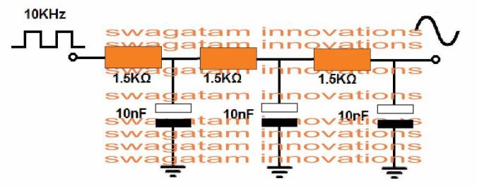
Hi Swagatam,
Many Thanks
My frequency range would be 60hz/65 on 220/240 vac
Lastly is this diagram you uploads is for left and right output connection of 12-0-12 transformer.
Best Regards,
Romeo
Hi Romeo,
Can you please tell what exactly are you trying to make, is it an inverter? If it’s an inverter then this concept will not work.
I provided this for converting your IC 555 square wave into sine wave!
Hi Swagatam,
Yes it is inverter and i used ic555 and a transformer 12-0-12/230 vac
Thanks
Romeo
I am sorry Romeo, a sine wave input cannot be used from the DC side for an inverter…you will have to use an SPWM at the DC side and then refine the output on the AC side with LC filter or simply with capacitors.
study ic 8038 wave form generator .
Hi swagadam,
i am moha, i really appriciated to you doing very good guidence upcoming engineers inspriation.
i need some information about transformers core max saturated frequency like Iron core, ferite core
pls reply and thankful to you
Thank you Moha,
I am not sure about the exact frequency range for these variants, but it seems 20 to 200 Hz is suitable for iron core coils and 10kHz to 100kHz for ferrite based coils.