In this post we are going to make an LCD 220 V mains operated timer using Arduino whose countdown time can be witnessed via 16 x 2 LCD display.
Introduction
The proposed LCD timer circuit is general purpose timer with display and few buttons for setting the time.
Once the time is set output goes high and starts countdown the time and when it reach 00:00:00 (Hour: Minute: Seconds) the output goes low. You may modify this project for your customized needs.
Now back to the project.
We always worry on our electrical or electronic devices which ran for too long just because we forget them to switch off them.
Time critical electrical and electronic devices like electric cooker, low profile battery chargers, heaters etc. need to be switched off at right moment otherwise we may end up reducing the life time of the gadgets or the processed end item such as food will be unpleasant to consume.
Low profile battery chargers might not have timer or battery monitoring system which might damage the battery’s life span if we left on charge for long time.
We can say hundreds of examples like these, to escape from such bad results a timer socket can be used.
A timer socket is a simple timer which is connected to AC socket and the time critical devices will be connected at output of the timer socket. The user has to input the time using button or dials for how long the connected devices should be powered.
Once the pre-set time is reached the device will be cut-off from the power supply.
The Design:
The proposed LCD socket timer project consists of Arduino which acts as brain of the project, a 16 x 2 LCD display which shows the remaining time, three buttons for setting the time and a relay for connecting and disconnecting the output AC supply.
Circuit Diagram:

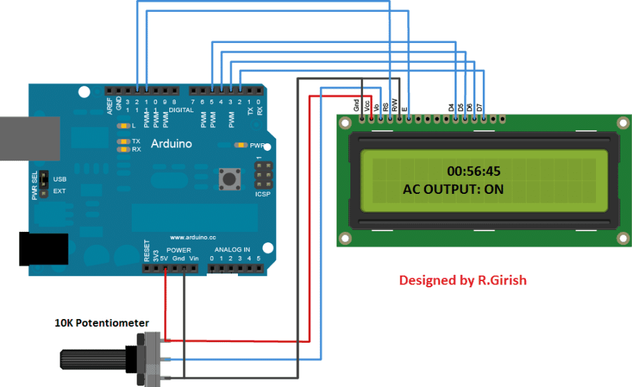
The above circuit is the arduino to LCD display connection, a 10K potentiometer is provided for adjusting the contrast of the display. Rest of the above connections are self-explanatory.
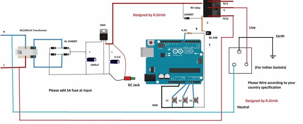
The circuit needs power to operate so, a simple regulated power supply is provided; it can output constant 9V to arduino and relay.
S1, S2 and S3 are push buttons by which the user can set time. S1 is hour button S2 is minute button and S3 is start button.
A 1N4007 diode is connected across the relay terminal to absorb high voltage back EMF from the relay while switching.
Use at-least 5A relay and 5A output socket. Connect a 5A fuse at the input supply. Always use 3-pin plug at input; don’t skip earth wiring and don’t interchange Live and Neutral lines.
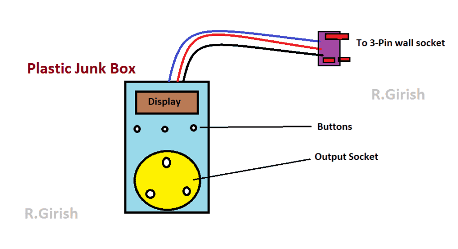
Circuit Layout:
Program Code:
//-------Program Developed by R.Girish---------//

#include <LiquidCrystal.h>

LiquidCrystal lcd(12,11,5,4,3,2);

const int hbtn = A0;

const int mbtn = A1;

const int start = A2;

const int relay = 7;

unsigned int hrs = 0;

unsigned int Min = 0;

unsigned int sec = 60;

boolean Hrs = false;

boolean Minlt = true;

void setup()

{

lcd.begin(16,2);

pinMode(hbtn, INPUT);

pinMode(mbtn, INPUT);

pinMode(start, INPUT);

pinMode(relay, OUTPUT);

digitalWrite(hbtn, HIGH);

digitalWrite(mbtn, HIGH);

digitalWrite(start, HIGH);

digitalWrite(relay, LOW);

lcd.clear();

lcd.setCursor(0,0);

lcd.print("Please set time:");

lcd.setCursor(0,1);

lcd.print("Hour:00 Min:00");

}

void loop()

{

if(digitalRead(hbtn) == LOW)

{

Hrs = true;

hrs = hrs + 1;

lcd.clear();

lcd.setCursor(0,0);

lcd.print("Please set time:");

lcd.setCursor(0,1);

lcd.print("Hour:");

lcd.print(hrs);

lcd.print(" ");

lcd.print("Min:");

lcd.print(Min);

delay(300);

}

if(digitalRead(mbtn) == LOW && Minlt == true)

{

Min = Min + 1;

lcd.clear();

lcd.setCursor(0,0);

lcd.print("Please set time:");

lcd.setCursor(0,1);

lcd.print("Hour:");

lcd.print(hrs);

lcd.print(" ");

lcd.print("Min:");

lcd.print(Min);

if(Min == 60)

{

Minlt = false;

}

delay(300);

}

if(digitalRead(start) == LOW)

{

if(hrs != 0 || Min != 0)

{

digitalWrite(relay, HIGH);

if(Min != 0)

{

Min = Min - 1;

}

while(true)

{

lcd.clear();

lcd.setCursor(5,0);

lcd.print(hrs);

lcd.print(":");

lcd.print(Min);

lcd.print(":");

lcd.print(sec);

lcd.setCursor(0,1);

lcd.print(" AC OUTPUT: ON");

sec = sec - 1;

delay(1000);

if(hrs == 0 && Min == 0 && sec == 0)

{

digitalWrite(relay, LOW);

lcd.clear();

lcd.setCursor(5,0);

lcd.print("0:0:0");

lcd.setCursor(0,1);

lcd.print(" AC OUTPUT: OFF");

while(true){}

}

if(sec == 0)

{

sec = 60;

if(Min != 0)

{

Min = Min - 1;

}

}

if(Min == 0 && Hrs == true)

{

hrs = hrs - 1;

Min = 60;

if(hrs == 0)

{

Hrs = false;

}

}

}

}

}

}

//-------Program Developed by R.Girish---------//
How to operate this LCD Socket Timer:
• Connect the LCD timer to 220 V AC mains and connect you device at output of the timer’s socket.
• It will display “Hours: 00 Min: 00”. Press the hour (S1) or minute (S2) buttons to set the time.
• Pressing the buttons will increment the count.
• Once you set the time, press start button (S3). The output turns ON.
• The output turns OFF when the display reads 0:0:0.
NOTE: The timer displays “60” instead of “00” for minutes and seconds, which is same as traditional timers and clock counts 00 to 59 for 60 seconds. Here the timer counts 1 to 60 for 60 seconds.
If you have any questions regarding this project feel free to express in the comment section.
Hello sir,
Could you add 2-USB ports to the design to charging smartphones.
Regards,
Hello Saad, the indicated LM338 output can be easily terminated with USB connectors for accomplishing USB ports.
Good day sir
I Hope your fine
This Webside is very useful for Lerner as me
I am not related to this field but hope you understand my requirements
Sir please give a ieda for encobeter control setting by timer switch using Arduino with display
My requirements is like this
I need use R1 for encobetr temperature elements any he source for hetting
R1 function is like this for example I st temperature 35° the R1 should be cut off at 35° and below it shudder be on
R2 I will use for heater that boil the water I can get better humidity for example I set humidity at 60%65 The heater shudder be of
R3 I will use for circulation fan
R4 for egg turning motor 3 time in 24 houre on for few seconds
R5 for one more fan that is needed to on in high temperature conditions for east
Need to adjust with as you show abow cicuit s1 s2 s3 etc
I think this easy to adjust te timing
Sir need progarming and ieda for circuits using Arduino
Which is better you know that
I hope you respond me better
Hi Imran, sorry I am not so good in Arduino coding, so I won’t be able to help you in this regard.
Ok sir
But you can refer to
Sir R.GR
Yes I can do it but your explanation is not correctly understandable. if you can write it with good English then I’ll surely refer it to Mr. GR.
Dear sir
With very sorry for that
You tell me where I cannot explain properly?
how muc I know will tray to explain better.
Imran,
please use correct spelling for all the words, and only explain what functions you want from the circuit in a step-wise manner, like 1) 2) 3)….
Hi Imran,
Please see whether I am correct:
1) The incubator should maintain 35 degree Celsius.
2)You need to maintain humidity of 60 to 65 % by vaporizing water.
3) You use the fan inside the incubator to spread the temp and humidity.
4) You need another fan to control during higher temperature (which will dissipate the heat outside).
Am I correct regarding your request? if not please mention in the reply.
Regards
YES sir it is correct
But one thing more need to add it that is eggs turning moter
That moter need to run 3tim in 24 hours for 3 to 5 second only ,,
I need to ask if it possible we can add switch in this circuit?
Switch mean S1,S2,S3 as you used above timer circuit
For example after progarming and redy to every thing
When ever we need to adjust temperature and humidity we can adjust by that switch ?
I mean by manually?