While Li-Ion and Lithium polymer electrolyte (LiPo) batteries possess unmatched energy density, Lithium-based batteries are costly to produce and need meticulous handling along with a cautious charging.
With the advancement of nanotechnology, the manufacturing process of the cathode electrode for these batteries has seen a substantial improvement.
The break through nanotechnology-based high-load LiFePO4 cells are more advanced than the traditional Li-ion or Lipo cells.
I have explained more:
What is LiFePO4 Battery
The lithium iron phosphate battery (LiFePO4 battery) or LFP battery (lithium ferrophosphate), is a form of lithium-ion battery which employs LiFePO4 as the cathode material (inside batteries this cathode constitutes the positive electrode), and a graphite carbon electrode having a metal support forming the anode.
The energy density of LiFePO4 is smaller compared to the conventional lithium cobalt oxide (LiCoO 2) chemistry, as well as features a smaller working voltage.
The most crucial downside of LiFePO4 is its reduced electrical conductivity. As a result, every one of the LiFePO4 cathodes into account are in reality LiFePO4/C.
Owing to cheaper costs, minimal toxicity, precisely specified performance, extensive stability, etc. LiFePO4 has become popular in number of vehicle based applications, utility scale stationary applications, and also in inverter, converter applications.
Advantages of LiFePO4 Battery
The nano phosphate cells take the pros of traditional lithium cells and merge them with the advantages of nickel-based compounds. All these happen without experiencing the disadvantages of either side.
These ideal NiCd batteries have several perks like:
- Safety – They are non-flammable so there is no need for a protection circuit.
- Robust – The batteries have a high cycle life and a standard charging method.
- High tolerance to heavy loads and fast charging.
- They have a constant discharge voltage (a flat discharge curve).
- High cell voltage and low self-discharge
- Superior power and compact energy density
Difference Between LiFePO4 and Li-Ion Battery
Conventional Li-ion cells are equipped with a minimum voltage of 3.6 V and a charge voltage of 4.1 V. There is a 0.1 V difference at both these voltages with various manufacturers. This is the main difference.
The nano phosphate cells have a nominal voltage of 3.3 V and a suppressed charged voltage of 3.6 V. The normal capacity of 2.3 Ah is quite common when pitted against the 2.5 or 2.6 Ah capacity offered by standard Li-Ion cells.
The more prominent dissimilarity is in the weight. The nano phosphate cell weighs only 70 g whereas its counterpart, the Sony or Panasonic Li-Ion cell has a weight of 88 g and 93 g respectively.
The main reason for this is shown in Figure 1 where the casing of the advanced nano phosphate cell is made of aluminium and not sheet steel.

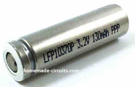
Additionally, this bears another advantage over the conventional cells as aluminium is better at improving heat conduction from the cell.
One more innovative design is the casing which forms the positive terminal of the cell. It is built with a thin layer of ferromagnetic material that forms the real contacts.
Charging/Discharging Specifications and Working
To prevent premature damage to the battery, we recommend applying the maximum allowed charging current/voltage, in case you needed to verify the specifications from the datasheet.
Our small experiment revealed the properties of the battery changed. At every charge/discharge cycle, we recorded a dip in capacity around 1 mAh (0.005%) of the minimum capacity.
At first, we attempted to charge our LiFePO4 cell at the full 1 C (2.3 A) and set the discharging value at 4 C (9.2A). Astonishingly, throughout the charging sequence, there was no increase in cell temperature. However, during discharging, the temperature elevated from 21°C to 31°C.
The discharge test for 10 C (23 A) went well with a recorded cell temperature rise of 49°C. Once the cell voltage reduced to 4 V (measured under load), the battery provided a mean discharge voltage (Um) of 5.68 V or 2.84 V on each cell. The energy density was computed to be 94 Wh/kg.
At the same size range, the Sony 26650VT cell presents a higher mean voltage of 3.24 V at 10 C discharge with a lower energy density of 89 Wh/kg.
This is lower than the LiFePO4 cell’s density. The difference can be attributed to decreased cell weight. But, the LiFePO4 cells have significantly lower performance than the LiPo cells.
The latter is frequently applied to modelling circuits and they have a mean discharge voltage of 3.5 V or more at 10 C. In terms of energy density, the LiPo cells have also the upper hand with ranges between 120 Wh/kg and 170 Wh/kg.
In our next examination, we fully charged the LiFePO4 cells at 1 C and cooled them later to -8°C. The ensuing discharge at 10 C happened at room temperature which is around 23°C.
The surface temperature of the cells had increased to 9°C after that. Still, the cell’s internal temperature must have been significantly lower although its direct measurement was not possible.
In Figure 2, you can see the terminal voltage (red line) of the cooled cells dived in the beginning. As the temperature rose, it returned to the same level as if the test was conducted with the cells at ambient temperature.
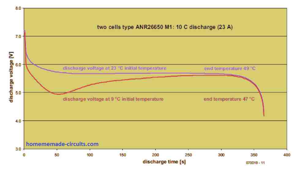
Surprisingly, the difference in the final temperature is low (47°C against 49°C). This is because the internal resistance of the cells is dependent on the temperature. That means when the cells are cold (low temperature), substantially more power is dissipated internally.
The next examination was related to the discharge current where it increased to 15 C (34.5 A), the cells presented more than their minimum capacity as the temperature escalated to 53°C from 23°C.
Testing Extreme Current Capacity of LiFePO4 Cells
We have shown you a simple circuit configuration in Figure 3. We used a low resistance circuit to measure the peak current levels.
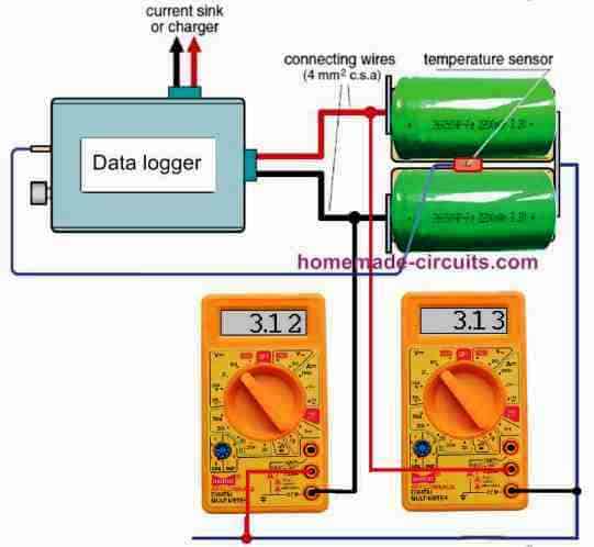
The combination of resistances including the 1 mΩ shunt resistor, the built-in resistance of the 100 A current sink and its associates (cable resistances and contact resistances in the MPX connector).
The extreme low resistance prevented the discharge of a single charge from going more than 65 A.
Therefore, we attempted delegating the high current measurements using two cells in series like before. Due to that, we could measure the voltage between the cells using a multimeter.
The current sink in this experiment may have been overloaded because of the cell’s rated current of 120 A. By limiting the extent of our evaluation, we monitored the temperature elevates at 15 C discharge.
This showed that it is not fitting to test the cells all at once at their rated continuous discharge rate of 30 C (70 A).
There is substantial evidence that a cell surface temperature of 65°C during discharge is the upper limit for safety. So, we constructed the resulting discharge schedule.
Firstly, at 69 A (30 C) the cells are discharged for 16 seconds. Then, it was followed by alternating ‘recovery’ intervals of 11.5 A (5 C) for half a minute.
After that, there were 10-second pulses at 69 A. Finally, when either the minimum discharge voltage or maximum permissible temperature was achieved, the discharge was operation was ended. Figure 4 depicts the results that were obtained.
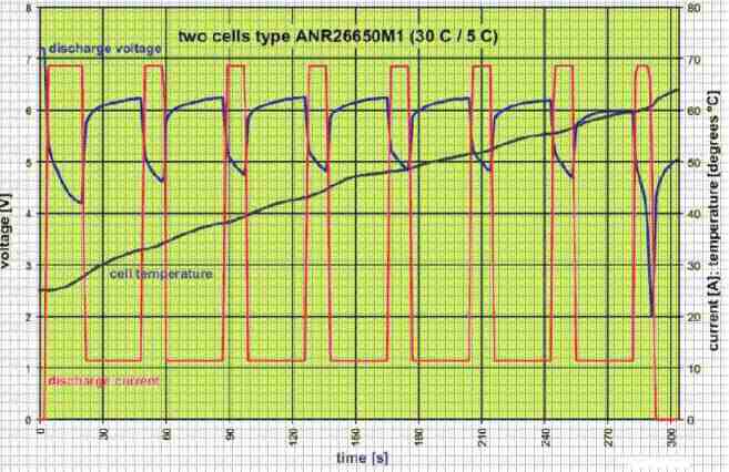
Throughout the high load intervals, the terminal voltage dropped quickly, representing that the lithium ions inside the cells have restricted and slow movement.
Still, the cell improves swiftly during the low-load intervals. Though the voltage slowly falls as the cell is discharged, you may find considerably less accurate voltage drops by the higher loads, as the cell temperature increases.
This validates how the temperature is dependent on the internal resistance of the cell.
We recorded an internal resistance to DC to be about 11 mΩ (datasheet presents 10 mΩ) when the cell is half discharged.
When the cell had fully discharged, the temperature had risen to 63°C, which exposes it to safety risks. This is because there is no additional cooling for the cells thus, we stopped from proceeding to testing with longer high-load pulses.
The battery gave an output of 2320 mAh in this test which was greater than the nominal capacity.
With a maximum difference between the cell voltages at 10 mV, the matching between them was outstanding throughout the test.
The discharge at full load was halted when the terminal voltage achieved 1 V per cell.
A minute later, we saw a recovery of 2.74 V open circuit voltage over each of the cells.
Fast Charging Test
Fast charging tests were conducted at 4 C (9.2 A) without incorporating an electronic balancer but we constantly checked the individual cell voltages.
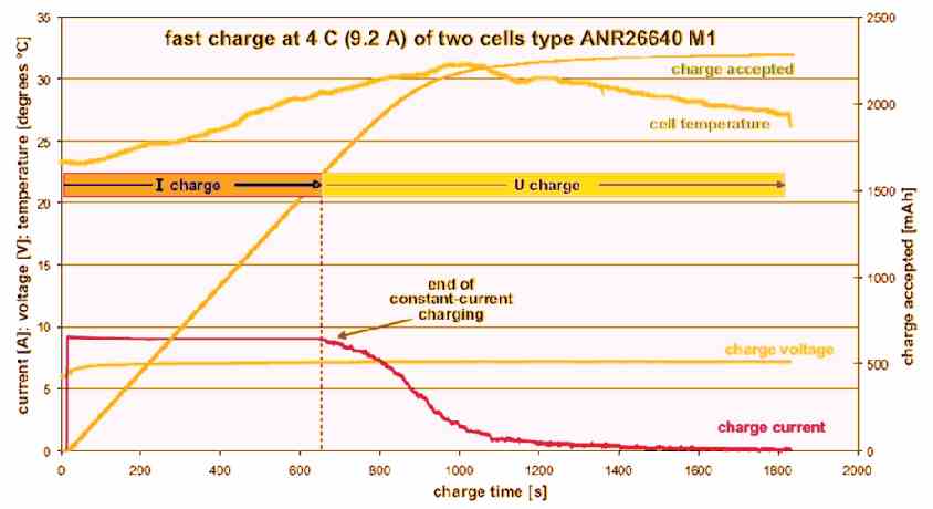
When using lead-acid batteries, we can only set the initial charging current due to the maximum and limited voltage delivered by the charger.
Also, the charging current can only be set after the cell voltage had risen to a point where the charge current starts reducing (constant current/constant voltage charging).
In our experiment with LiFePO4, this happens after 10 minutes where the duration is reduced by the effect of the shunt in the meter.
We know the cell is charged to 97% or more of its nominal capacity after 20 minutes had elapsed.
Furthermore, the charge current at this stage has dropped to 0.5 A. As a result, a ‘full’ state of the cells will be reported by a fast charger.
Throughout the fast charging process, the cell voltages sometimes moved a little bit from each other, but not beyond 20 mV.
But for the overall of the process, the cells finished charging at the same time.
When experience fast charging, the cells tend to warm up quite a bit, with the temperature somewhat lagging the charge current.
This can be attributed to losses in the internal resistance of the cells.
It is fundamental to follow safety precautions when charging the LiFePO4 and not beyond its suggested charging voltage of 3.6 V.
We tried to sneak past a little and attempted to ‘overcharge’ the cells with a terminal voltage of 7.8 V (3.9 V per cell).
It is not at all recommended to repeat this at home.
Although there was no strange behavior such as smoking or leaking and the cell voltages were also almost equal, but the overall outcome did not appear to be too beneficial.
- The 3 C discharge supplied an additional 100 mAh and the mean discharge voltage was relatively higher.
- What we mean to say is overcharging causes a small upheave in energy density from 103.6 Wh/kg to 104.6 Wh/kg.
- However, it is not worth it to endure the risks and possibly subject the life of the cells to permanent damage.
Battery Chemistry and Evaluations
The concept of applying FePO4 nanotechnology together with a lithium battery chemistry is to elevate the surface area of the electrodes over which reactions can take place.
There space for future innovation in the graphite anode (negative terminal) looks cloudy, but regarding the cathode, there is substantial progress.
At the cathode compounds (typically oxides) of transition metals are utilized for ion capture. Metals like manganese, cobalt and nickel which are used by cathodes have been in mass production.
Moreover, each of them has its respective pros and cons. Manufacturer opted for iron, particularly iron phosphate (FePO4) in which they discovered a cathode material that even at lower voltages is functional enough of enduring extreme battery capacity.
Primarily, Li-Ion batteries are only chemically stable within a tiny voltage range; 2.3 V to 4.3 V. At both ends of this range certain conciliation are necessary for terms of service life. Practically, an upper limit of 4.2 V is considered acceptable while 4.1 V is recommended for prolonged life.
Conventional lithium batteries which are made up of several cells connected in series stay within the voltage limits through electronic add-ons like balancers, equalizers or precise voltage limiters.
The complexity of these circuits increase as the charge currents increase resulting in additional power losses. For users, these charging devices aren’t too preferable as they would rather prefer cells that can endure deep discharge.
Furthermore, users would also like a wide temperature range and the possibility of quick charging. All these put the nano-technology FePO4 based LiFePO4 cells become the favorites in the innovation of Li-Ion batteries.
Preliminary conclusions
Because of their elaborately flat discharge voltage curves which anchor the execution of high-current industrial applications, the LiFePO4 or the FePO4-cathode Li-Ion cells are very desirable.
Not only they have substantially more energy density than conventional Li-Ion cells, but also an exceedingly high-power density.
The combination of low internal resistance and low weight bodes well for the replacement cells depending on nickel or lead in high power applications.
Typically, cells cannot endure continuous discharge at 30 C without experiencing a hazardous rise of temperature. This is disadvantageous because you wouldn’t want a 2.3 Ah cell to discharge at 70 A in just two minutes. In this type of applications, the user gets wider options than traditional lithium cells.
On the flip side, there is a continuous demand for quicker charging, particularly if the charging duration can be lessened drastically. Probably this is one of the reasons why LiFePO4 cells is available in 36 V (10 series cells) professional hammer drills.
Lithium cells are best deployed in hybrid and environmentally friendly automobiles. Using just four FePO4 cells (13.2 V) in a battery pack yields 70% lesser weight than a lead-acid battery. Improved product life cycle and significantly higher energy on top of power densities have supported the development of hybrid vehicle technology largely in zero-emission vehicles.
Hi Mr. Swagatam;
I have FNIRSI 5012H Oscillator. And the its instruction manual says that it has the built-in 3000 mAh Lithium Battery. Its input voltage is 5 or 3,7V that I use my phone charger to charge the device. However this phone charger is 1A, so could you please advise that if this is higher value for charging the 3000 mAh battery or that current value is not issue for the lithium type batteries?
Hi Suat,
1 amp current not an issue for the Li-ion battery since it can be charged at 1C rate meaning with full 3000 mA current, but make sure to cut off the charging as soon as the battery reaches 4.2V.
Sir, will a bms for 18650 battery work well if used for 32560 battery?
Hello Evangel, If the battery specifications is higher than the BMS controller specifications, then it will not work. I guess 32560 battery is more powerful than 18650 battery therefore BMS for 18650 battery cannot be used for 32560 battery
Good day Swagatam,
Please how do I use 3.2v Lifepo battery to power 50watt led
Hi Evangel, What is the voltage rating of the LED.
They wrote 3.2v 50watt for both the battery and the LED. I’m only sure of the battery voltage and the LED wattage, but not sure of the LED voltage.
My issue is, if I have a 3.2v battery and want it to power a 12v 50watt LED, is it safer to use DC booster or design 3.2v 50watt LED for myself?
Thanks
If it’s 3.2V rated then the current requirement of the LED would 50 /3.2 = 15 amps. To satisfy this the Lipo battery would be required to be rated at 20 Ah . For a 12V 50 watt LED also the battery requirement would be the same and a high boost converter would be required. Yes DC to DC boost converter would be safe if it’s output is current controlled.
Many thanks.
I’m very grateful.
God bless you for all you do for humanity
You are most welcome!
Hello Swagatam, thanks for this detailed article. I must say this is a great blog overall.
I am looking into replacing car Lead Acid starter battery with Lifepo4. We know that 4 Lifepo4 cells connected in series is sufficient to start a car, thanks to high discharge Lifepo4 cells available these days (Eg: 38120HP) at their nominal voltage (3.2 volts). The issue is charging the battery pack of 4 cells in series with the alternator. I have been researching online here are my observations and doubts:
1. In this use case, the battery pack will get discharged slightly since the alternator starts charging it immediately after a “slight” discharge (single crank).
2. In this use case it’s advisable to charge the battery to 3.2 volts for its longevity. This would allow the battery pack to be utilized for maximum charge/discharge cycles. Charging it to 3.65 volts is simply not required.
3. Can we charge Lifepo4 cells in series? Alternator voltage varies from 13.8-14.7 volts depending on RPM. If we limit this voltage using a 13 volt zener diode based circuit to ensure that each cell in the battery pack gets 3.25 volts, does it solve the “top up charging” issue?
Please share your thoughts on the points above. I may be completely off target with regards to charging, there are many online sources with conflicting information. Their are many chinese ready made battery packs with poor circuit design; many of those simply have an active cell balancer and nothing else to prevent overcharge/overdischarge and thus the battery packs die soon. However I believe proper circuit design can help us realize the benefits of Lifepo4 over lead acid in car/motorcycle starter battery usage scenario.
Thank you Som!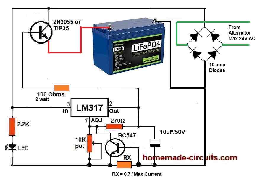
In general, you can charge a Lifepo4 cells in series using a regulated DC charger circuit. However, if you consider this too much technically then you might have to go for a balance charger for charging series batteries. According to me a well regulated charger with voltage and current control feature might be just enough to charge your Lifepo4 battery safely.
Here’s the design which you can try for charging your battery through an alternator:
" rel="ugc">
Make sure to adjust the output voltage to a perfect 14.5 V using the 10K pot and set the max current to 50% of the battery’s Ah rating.
Use large heatsinks for the 2N3055 transistor.
Hello, thanks for the reply and for whipping up the circuit. The bridge rectification part of the circuit would not be needed in a typical car/bike scenario since the alternator output reaches the battery through a regulator rectifier which outputs 13.8-14.7 volts DC depending on RPM.
Upon further research I found that during discharge when cranking, the 4 LifePo4 cells may be discharged unequally, so it is important to ensure each of the 4 cells are charged back at 0.5 charging rate to the same target voltage, which I want to be around 3.2 volt. Guess a basic BMS is needed for battery pack longevity anyway!
In that regard i would trust the reliability of a DIY 4S BMS which can tolerate 100amp discharge current, rather than trusting some Chinese BMS.
Designing a BMS as mentioned above could be your next project…just an idea 🙂
Thank you for your feedback, appreciate it!