The light activated water level controller circuit explained here has the advantage of being corrosion free and much reliable than the traditional moisture sensor type of water sensors.
Circuit Operation
One slight downside of this LDR based sensor is that the tank interior always needs to be illuminated by some kind of light source such as a bulb or a LED.
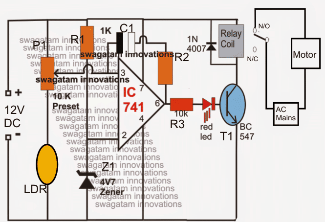
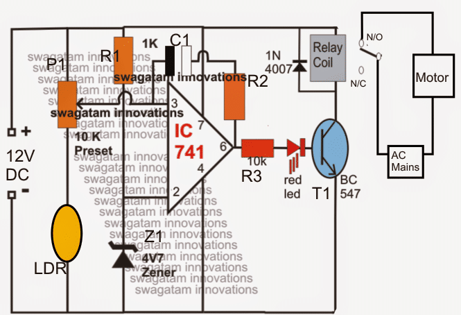
A LDR sensor is configured with a IC 741 opamp and adjusted carefully such that the light falling over the LDR keeps the pin3 of the IC low in response to a focused light source and with reference with pin2 set voltage.
In an event the light across the LDR is disturbed, induces an imbalance across the pinouts of the IC triggering the opamp output to go high and activate the connected relay and the load.
In the present light activated water level controller circuit, an LDR is utilized and positioned across the the area of the tank where the level is to be monitored, or a relay is to be activated in response to a rise in the water level.
Circuit Diagram

As long as there's an absence of water across the sensing zone, the LDRs experience the incident light (positioned from the opposite side, inside the tank) which in turn keeps pin3 of the IC low, however when water starts rising and tends to cover the LDR in the path, reverts to a high at pin3 of the IC which instantly prompts the opamp output to go high activating the relay and the pump.
A hysteresis control feedback resistor across the opamps (R2/C1)) make sure that the once the situation is sensed it stays latched for some predetermined time and the pump motor is allowed to run until the water has reached the bottom of the tank.
The time for which the opamp stays latched may be determined by adjusting the feedback resistor connected between the output and the input pins of the opamp.
